SKETCHNBUILD SNB-K3A User manual
SNB‐K3AAUTOMATICEDGEBANDERMANUAL
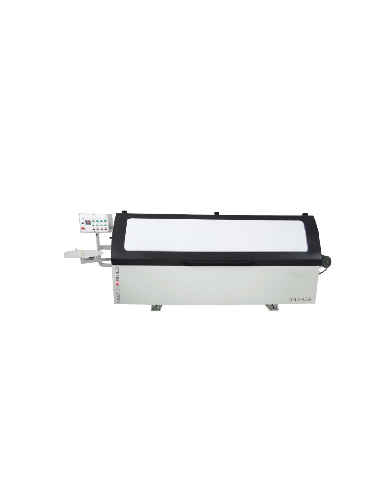
SNB-K3A AUTOMATIC EDGE BANDER
1

1
Table of Contents
Packing List…………………………………………………………………2
Foreword………………………………………………………………………3
Chapter 1:Safety feature flag graphic………………………………4
Chapter 2: Care and maintenance……………………………………….8
Chapter 3: Mechanical uses and features……………………………10
Chapter 4: Mechanical structure……………………………………….10
Chapter 5: The main technical parameters………………………….11
Chapter 6: Transport……………………………………………………….12
Chapter 7: Equipment Installation…………………………………….12
Chapter 8: Equipment use and adjustment…………………………….14
Chapter 9: Abnormal phenomenon and its elimination……………….23
Chapter 10: Thanks………………………………………………………….24

2
Packing List
1、 Automatic edge banding machine: 1
2、 Instructions: 1
3、 Tools:
Allen wrench: 1
Cross screwdriver: 1
Flathead screwdriver: 1

3
Foreword
Thank you for choosing our company's woodworking machinery products.
Automatic edge banding machine Instructions mainly for construction,
performance, safe operation, maintenance, and transportation, storage and so
matters do a comprehensive, detailed, and efficient personnel to manage the
economy, good use of the above equipment, provides the basic knowledge.
This specification rules and guidelines will help you to safe and effective
use of the machine. Before the operation and maintenance manual must be read
and comply with the precautions to prevent accidents due to illegal operation
and maintenance may cause serious injury or death and.
Due to continuous product improvements and do change with the contents of
this manual are subject , without prior notice, please user understanding.
Warning
Before starting operation and maintenance, operation and maintenance
personnel must observe the following:
Before the operation or maintenance, be sure to read and understand this
manual.
To read this manual safety notice and adhere to the mechanical security
identification and must be completely understood.
To save this manual for the specified storage location, and should read the
manual on a regular basis.
If this manual has been lost or defaced can not read, please immediately
contact the company or distributor.
Safety identification and use language
To help you safely use automatic edge banding machine, pasted on the
specification and the signs of the mechanical safety precautions in order to
provide a description and methods to avoid such dangerous situations involving
potentially dangerous.
The following identifies the term indicates that there could cause personal
injury or damage to the potential danger. In the present specification and
mechanical signs, following identification of potential terms used to indicate
the degree of hazard.

4
DANGER
Said that if not evade the consequences of the risk
will result in death or serious injury.
CAUTION
Said that if not avoid, potentially dangerous
consequences that may result in lower or moderate
injury or serious injury.
Solemnly declare
Due to property damage and personal injury caused by incorrect operation, the
company is not responsible.
Chapter 1:Safety feature flag graphic
1.1 General Security
(1) Before the operation, the operator must read the instructions carefully and
completely understood. Security managers should confirm skilled operator can
operate the machine.
(2) Operating equipment, maintenance, maintenance personnel must be trained,
familiar with the potential dangers of the machine and obtain the relevant
qualifications.
(3) Assembly, maintenance and repair personnel must fully understand the operating
instructions, and in strict accordance with the requirements of the job.
(4) After the machine stops, adjust or remove the protective device, be sure to pay
attention to some rotation, drive components, due to inertia will continue to
run for some time. Maintenance or adjustment should be in the danger of moving
parts completely stopped.
(5) Once the machine is abnormal or fault, the operator should immediately stop the
machine, cut off the power supply, gas supply, notify promptly repaired by
qualified service personnel.
(6) Handling, disassembly and assembly of the machine must be sufficient bearing
capacity lifting equipment.
(7) The machine must be specified purposes and requirements, otherwise it may cause
serious danger.
(8) Comply with the safety instructions and warnings for all machines, and to
maintain the integrity and clean safety instructions and warnings identified.

5
(9) Before operating the operator shall conduct a comprehensive safety inspection,
confirm the safety guards and safety devices of the machine before starting the
machine to normal after all.
(10) After machine maintenance, to ensure the safety devices and protective cover,
complete and accurate installation in the original location.
(11) Only off the power, gas supply, all the moving parts of the machine is completely
stopped and disconnect the power before they can repair, maintenance,
replacement and cleaning machine debugging.
(12) Replacement parts must use original parts, otherwise it will cause danger or
damage to the machine.
(13) In the case of the machine must be running unattended operator when the operator
leaves the machine, you must turn off the power.
(14) Always check all power lines and ground lines, ensure that the machine's
electrical system has good insulation and grounded. Not use defective wires.
(15) Prohibiting the use in wet or explosive environment, or they may cause serious
danger.
(16) Keeping the work environment clean, provide adequate lighting.
(17) Prohibit children and visitors close to the machine, the operator at least 18
years of age have the ability to predict the presence of dangerous machines.
(18) Do not drink after fatigue and have a hypnotic effect and taking similar drugs
operate the machine.
(19) The operator must not wear loose clothing, not wearing a tie, gloves or jewelry
(such as rings, bracelets, watches, etc.).
(20) Long hair must be wrapped with a wig and reliable, to prevent hair caught in
the machine inside.
(21) When operating the machine is recommended to wear the necessary personal
protective equipment, such as wearing ear protection to reduce the risk of
hearing loss.
1.2 Equipment usage rules
(1) At the discharge end of the machine should ensure that sufficient space-space
ratio should be at least the length of the longest length of the workpiece large
500mm.
(2) User-equipped blade, cutter and cutter machine sizes must comply with the
requirements of the original configuration, the user must be selected in line

6
EN847-1: blade and cutter, cutter blade and the rated speed of 1997 standard
requirements should not lower than its maximum speed shaft.
(3) Adjust the machine must be carried out in accordance with the provisions of this
specification by professionals, avoid touching knives and dangerous moving
parts.
(4) The machine must be connected before use and removal dust system must ensure
removal equipment has been working before starting the machine. Vacuum equipment
should be of sufficient air volume and velocity, which air volume of 800m / h,
a flow rate of 25m / s.
(5) Must cut off the power supply, gas supply when changing tools.
(6) Air Ministry during the repair work, disconnect the gas line to prevent
accidental operation of pneumatic components danger.
(7) Should regularly check the safety-related components of each safety interlock
switches, emergency stop switch, gas pressure sensor, temperature controller,
etc., to ensure reliable operation of these components. If abnormal, should be
repaired by qualified service personnel, replacement parts should be used
original parts
(8) Keep knives sharp, should be replaced blunt, deformed, defective blade, cutter
and cutter, otherwise there will be dangerous.
(9) Do not exceed the parameters of the processing specifications and technical
requirements of the deformation of the workpiece.
(10) Saw, milling, polishing wheel rotation direction to the right, should be
consistent with the direction of the machine ID, otherwise it will be dangerous.
(11)After the feeding device and the parts reach the maximum stable speed motor speed
can be fed.
Warning:
Failure to comply with these rules may lead to serious injury.
Machinery and transport dangerous to squeeze between the plate and the pressure
drag wheel, prohibit access to these parts of the machine is running, it may cause
serious injury.
Power supply isolation means does not have a pressure gas source isolation,
maintenance parts when closed pneumatic manifold isolation valve, and release the
residual pressure in the pipeline.
Melt glue pot surface temperature after turning off the power at the surface of
7
the machine will last longer period of time, prohibit hand directly touch the surface
of the melt glue pot and melt glue pot, to avoid burns.
1.3 Limitations of the surrounding environment:
Place the machine on the operating environment requirements
Power
Referring to the
body stickers
Relative humidity
90% No condensation
Power frequency
Altitude
≤1000m
Ambient temperature
0°C—40°C
Silo temperature
0°C—40°C
1.4 Noise statement:
Noise measurements were performed according to standard IS07960.
The machine noise level when the load is not greater than 82dB (A).
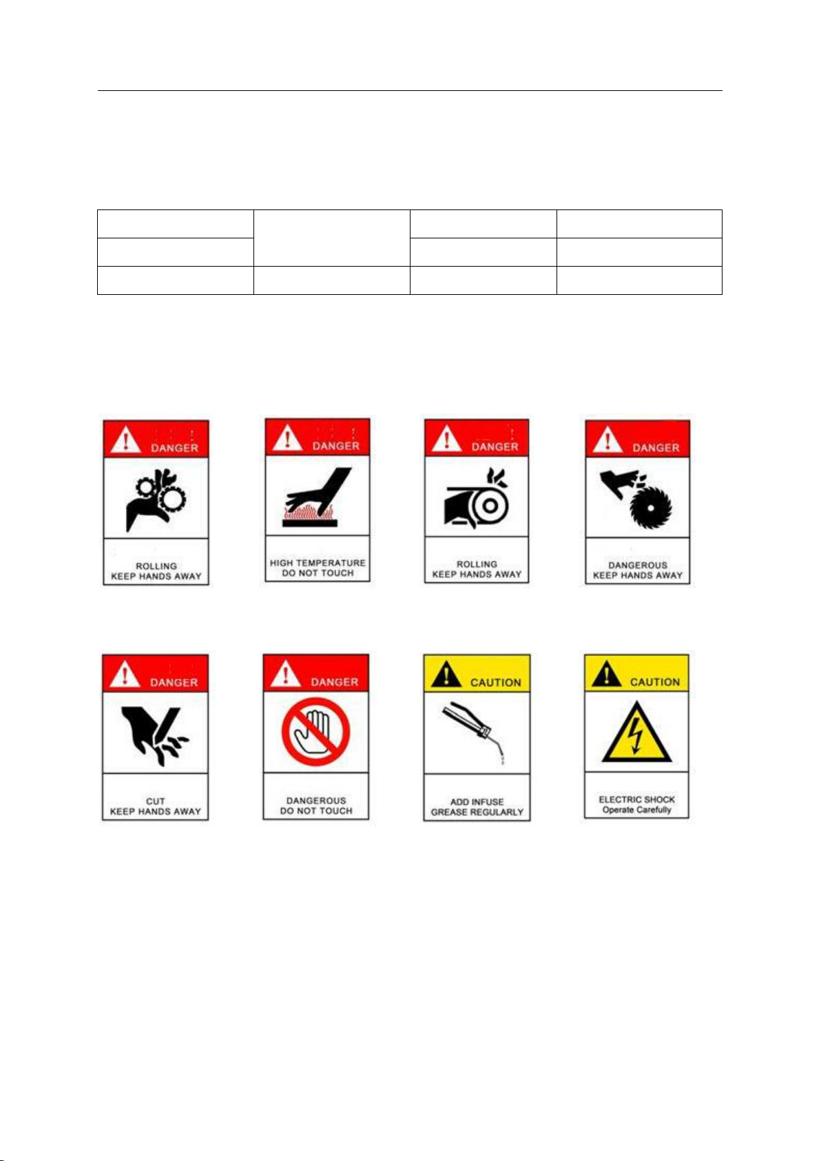
1.5 Logo Graphic:
ROLLING
KEEP HANDS AWAY
HIGH TEMPERATURE
DO NOT TOUCH
ROLLING
KEEP HANDS AWAY
DANGEROUS
KEEP HANDS AWAY
CUT
KEEP HANDS AWAY
DANGEROUS
DO NOT TOUCH
ADD INFUSE
GREASE REGULARLY
ELECTRIC SHOCK
OPERATE CAREFULLY

8
Chapter 2: Care and maintenance
Disclaimer: This device is a high-precision machinery and equipment, the need for
strict maintenance, strictly in accordance with the requirements of the equipment
necessary maintenance. Due to lack of maintenance failures caused by maintenance, not
free within the service range!
In order to ensure the normal operation of the machine for a long time, it must
perform regular maintenance and upkeep, partly due to the need of production, on the
other hand is the need to device usability and safety.
Before all maintenance, service and repair work, you must turn off the main power
switch and disconnect the power, strictly prevent accidental machine startup.
When the machine work, you must use the vacuum suction device.
Regular cleaning can prolong its life, and is an important prerequisite to ensure
that the workpiece to achieve good results. Therefore, after the class of equipment
must be cleaned and maintenance, for at least a week for a major clean-up equipment
and maintenance.
Regularly check the wear blade, cutter, blade, polishing wheels, so the device is
always kept in good working condition.
Only by mastering the expertise to understand the possibility of dangerous equipment
to allow maintenance personnel.
You can only use the original machine parts for maintenance, or else, it might give
operational risk.
See detailed maintenance schedule

9
Maintenance schedule
No.
Timetable
Area
Operation
Lubricants /
solvent
1
After the end
of the work
day
The whole
machine
a. The whole machine
cleaning sweeps, wipe clean
b. Clean up litter on the
chain sprocket crawler
c. Transmission parts
litter cleanup, waste silk
d. Clean up the excess melt
glue pot around
e. Each processing surface
anti-rust oil
f. Each oiling point
refueling
Rust oil/
3﹟Molybdenum
disulfide lithium
grease
2
Every 80
working hours
Glue pot
High
temperature grease injection
pressure of linear
bearing with grease gun
3﹟Molybdenum
disulfide lithium
grease
Active edge roller
Injection of oil with high
temperature grease gun
3﹟Molybdenum
disulfide lithium
grease
3
Every 200
working hours
Rubber box
driving chain
plate chain
Check chain tension
Timely adjustment
4
Every 2
months (400
hours)
Feed track
Using hand pressure pump to
lubricate the moving track
Lubricating oil
Feed track
Check chain tension, if

10
necessary to adjust
5
Timely
inspection,
when the
container
level becomes
low
Air source
processor
The oil cup filled with
lubricating oil 3/4
Mobil VG32 IS0 oil
Chapter 3: Mechanical use and characteristics
USE The machine is set machine, electricity, gas as one of the high-tech,
high-efficiency edge models. It is mainly used for roll edge type and hot melt adhesive
and wood panels, particleboard, blockboard, medium density fiberboard and other sheet
metal straight edge bonding and dressing, the processing after the sheet edge is evenly
and firmly, trimming smooth and more durable and beautiful.
Characteristics The machine can from the plate into the auto completion: adhesive
edge, end trim,fine trim,scraping and buff five functions, to avoid the manual
processing in the process of machining error, ensure the consistency of the size of
the processing. The machine has high automation degree, edge of good quality, high
production efficiency, and has the advantages of beautiful appearance, compact
structure, stable and reliable work is use of panel furniture manufacturer is one of
the important equipment.
Chapter 4: Machine tool
structure

11
Picture 1 Automatic edge banding machine
1、 Edge banding 2、end trimming 3、fine trimming 4、scraping 5、buffing 6、body
Chapter 5: Technical parameter
The main technical parameters of automatic edge banding machine
sheet thickness
10-50mm
edge thickness
0.4-3mm
minimum working plate width
≥50mm
minimum working length
≥140mm
higher than the maximum size of
sheet sapwood (per side)
2mm
feed speed
13m/min(constant speed)
compressed air pressure
0.7Mpa
power supply
see fuselage terminal box
Feed motor
1.5kW
Plastic box motor
0.37kW
End trim motor
0.55kW*2.200Hz.18000r/min

12
Fine trim motor
0.75kW*2.200Hz.18000r/min
Buff motor
0.18kW*2.50Hz. 1400r/min
heat
1.5kW
Preheat
0.12kW
Power
7.0kW
Electric current
15A
Fine trim milling
D=Ф68. d=Ф16(+0.017+0.006)
End trim milling
D=Ф100. d=Ф22
Hot melt (reference resources)
160-200℃
Machine size
3940×900×1800 (mm)
Machine weight
About 1500kg
Chapter 6: Transport
6.1 The machine can be carried through the body at the bottom of the forklift;
Warning:
In the beginning before moving, please confirm the lifting and handling equipment
should have sufficient bearing capacity.
In the handling and lifting process, should slow up the light, keep the balance.
Otherwise, it may affect the machining accuracy, and even damage the machine.
The lifting and handling process, prohibited under the machine and its adjacent
station, to prevent accidental injury.
If the machine must be stored, please keep the machine in the greenhouse and dry
environment, and the cover is sealed by a plastic bag.
Chapter 7: Machine installation
7.1 Machine installation:
(1) the installation of the machine should be far away from the vibration source.
(2) the operation room should be cement ground, and check whether the ground is
smooth. Avoid shaking when the machine is adjusted.
(3) should put the machine in close proximity to the power supply, air outlet, the
waste pumping outlet position, the workplace should ensure adequate lighting, the
luminous flux of not less than 500Lx. Suggested that the vacuum cleaner flow rate
is greater than 800m/h, the flow rate is 25m/s. The machine vacuum interface with
100mm, the pressure is greater than 1100Pa, the flow rate is greater than 12m/s.
(4) the rubber boiler waste gas and waste plastic must be concentrated discharge,
and should meet the requirements of local environmental protection.
(5) around the machine should be set aside enough space for proper installation
and maintenance of equipment. The size of the space is determined by the size of
the sheet to be processed.
13
(6) the machine must be surrounded by the largest sheet and other obstacles to set
aside 500mm free space.
Warning: narrow working space can lead to serious personal injury.
(7) in order to ensure the smooth machine, after placing the good machine, should
adjust the adjustment screw, so that the central position of the fixed table
vertical and horizontal horizontal meter readings are not more than 0.10/1000.
After the machine is fixed, the belt plate is installed on the working table.
7.2 Electrical installation:
7.2.1 Circuit installation
(1)User's distribution system should be equipped with over voltage protection device.
(2)Because the voltage frequency of each country is different, the voltage and
frequency of this equipment, please refer to the junction box office. Voltage
fluctuation range 10%, frequency fluctuation range 0.5Hz.
(3)The machine with 5 copper core wires, copper wires for power lines into the.
(4)The cross-sectional area of the grounding line should be not less than the phase
stack area.
(5)Ground resistance should not be greater than 4Ω.
(6)Power cord should be connected to the junction box in the lower part of the body.
7.2.2 Check before power on: the following inspection should be carried out before
the machine is powered on
(1)Check the movement of the moving parts should be no obstacle.
(2)Tool clamping should be firm.
(3)The lubricating parts should be good.
(4)Pneumatic three pressure gauge indication in 0.6Mpa.
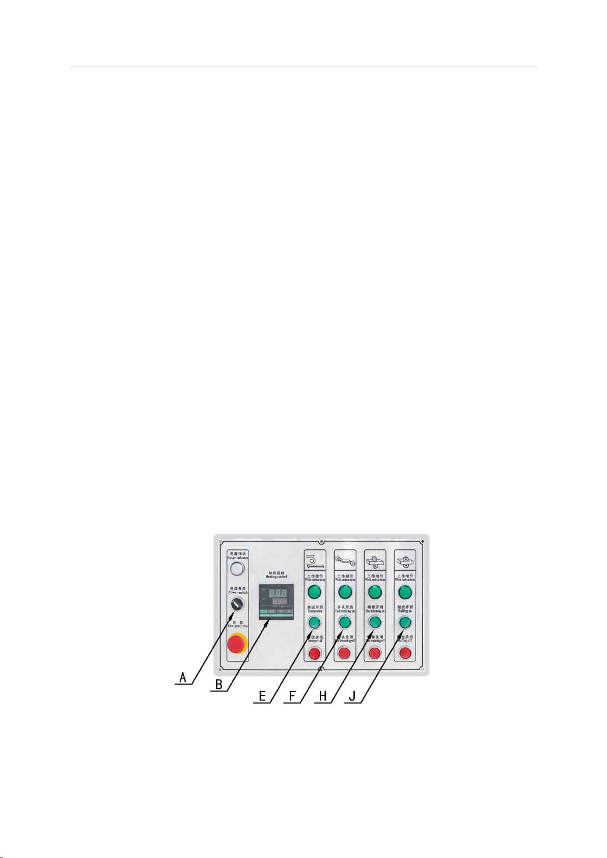
7.2.3 Electricity:(Figure 2)
Figure 2
(1)All emergency stop button reset.
(2)When the protective cover is not opened, the total power switch is closed, and
the starting switch of the control power switch A is opened, and the operation can

14
be carried out.
7.2.4 Power after the first boot
(1)After the power supply, turn on the power switch A. If the power indicator light
is normal, the connection is correct. Such as electricity without the power indicator,
should change the power supply to re open the power switch A, check the power indicator.
(2)Confirm the correct connection, set the thermostat B to the required value.
(3)After the actual temperature to reach the set temperature of ten minutes after
all the motor in order to start.
7.2.5 Shutdown:
(1)Switch off all motor switches.
(2)Switch off the control power switch A, cut off the control power supply.
(3)Turn off the main switch, the whole machine power off. Cut off the power.
7.2.6 Gas installation:
(1) before the installation, check the gas supply capacity of not less than 0.5m
/min 0.5-0.6Mpa fand air pressure.
(2) were inserted into the trachea machine nozzle used on aerodynamic inlet triple
in ventilation.
Chapter 8: Machine tool use and adjustment
This machine tool has passed the precise adjustment and the strict test before leaving
the factory, has not been related to the training or has not specially specially
specially specially to instruct not to be arbitrarily randomly to tune. In the process
of use, the user may need to adjust the machine according to the change of the material
specification. Such adjustments must be carried out by a specially trained
professional.
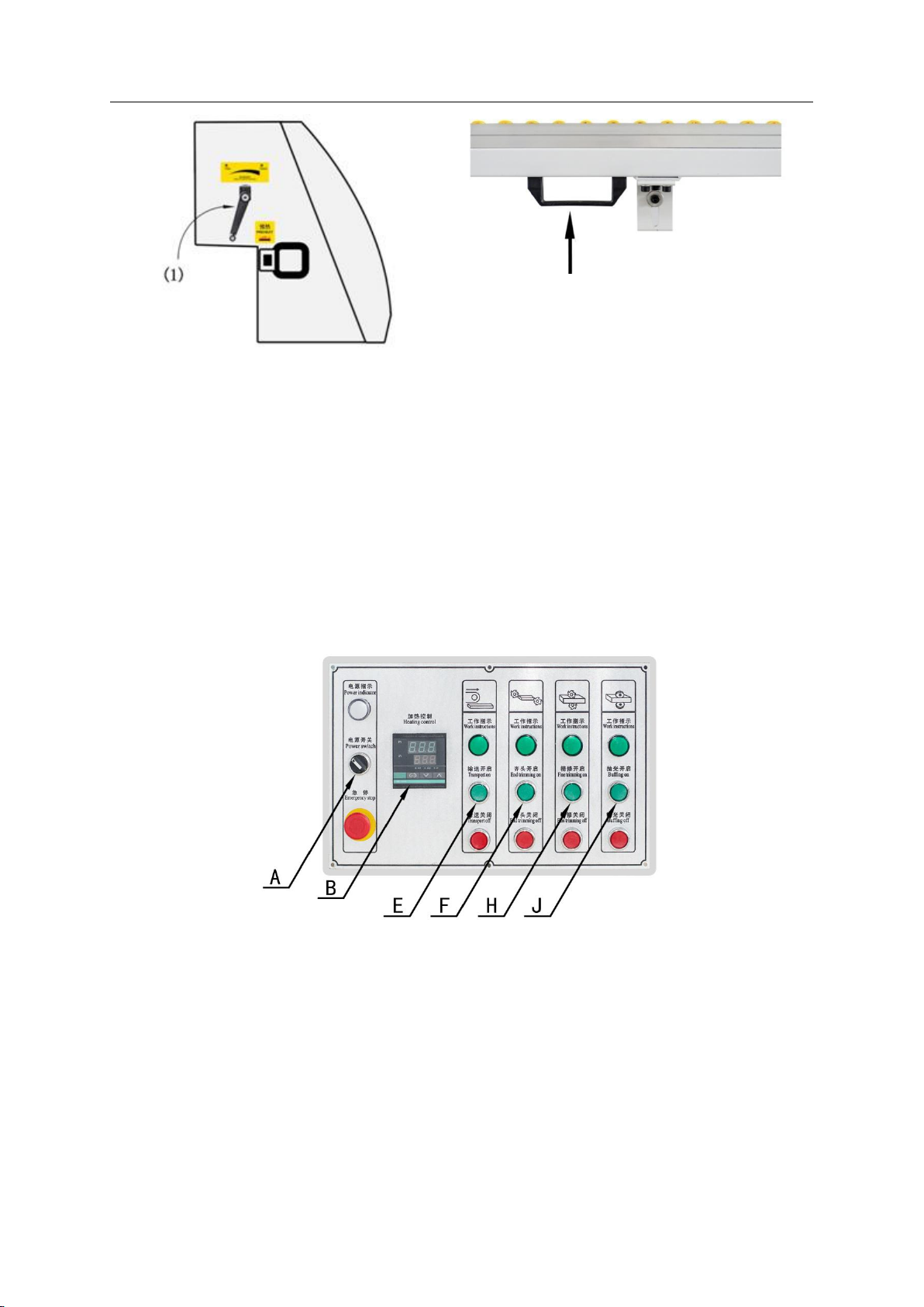
8.1 Plate thickness adjustment(Figure 3)
When the change of the thickness of the plate must be of material pressing height
corresponding adjustment: according to the thickness of the plate with special crank
rotation adjustment rod (1) to realize the numerical and the plate thickness is
consistent with that of the position of monitor. Clockwise rotation, the vertical plate
up, counter clockwise rotation, the vertical plate down.
8.2 After adjustment of supporting material device(Figure 4):
After the material holding device is mainly used for large workpiece edge support,
it can be adjusted according to the width of the workpiece. The adjustment method is
as follows: pull the handle on both ends of the support frame, and move it to the
appropriate position.
15
Figure 2
Figure 4
8.3 Control system(Figure 5):
Turn on the power control switch "A" start button, control power on.
Set the required temperature on the temperature control table B. When reaching the
set temperature, after ten minutes press the conveyor belt switch "E" start button,
conveyor belt running, press the corresponding switch motor operation.
In order to minimize the frequency converter, power outages, the system is not as
far as possible after the removal of artificial, to ensure the normal use of the
frequency converter.
When the wood into the machine touches the travel switch, push conveyor cylinder
edge forward. Board to enter the end of the trip to leave the trip, stop feeding.
Figure 5
8.4 Edge system:
This system adopts the edge banding machine mounted under the hot glue box, double
helix type glue feeding structure, ensure uniform glue glue feeding convenient. Edge
belt into the machine, roll edge away straight edge banding conveyor belt with sealing
device for workpiece linkage, with knurled wheel conveyor belt and the cylinder pressure
zone, knurled wheel is used for thin and soft edge banding. Banding belt pressing the
spring compression mode and pressure can be adjusted, into the edge belt, auto plate
spring pressure, the belt pressing roller and the roll round flower of complete tape

16
feeding action. Edge with upstream and downstream zone with limiting blocks are high
in the form of constraints and regulation to the attention of the press not loose not
tight, in order to ensure the smooth and not to the upstream and downstream with. Cut
off by quick exhaust valve with sealing, to ensure the rapid and effective cutting.
PVC edgeband with belt cutting method. Edge banding and the pressure between the plate
by means of gas moving horizontal pressing wheel device, the pressure of front and rear
wheel position and size can be adjusted, the edge belt and plate between the bonding
more solid and reliable. In the use of machine process, due to the change of
specification and the plate edge thickness increase or decrease in the edge zone, need
to adjust the following parts:
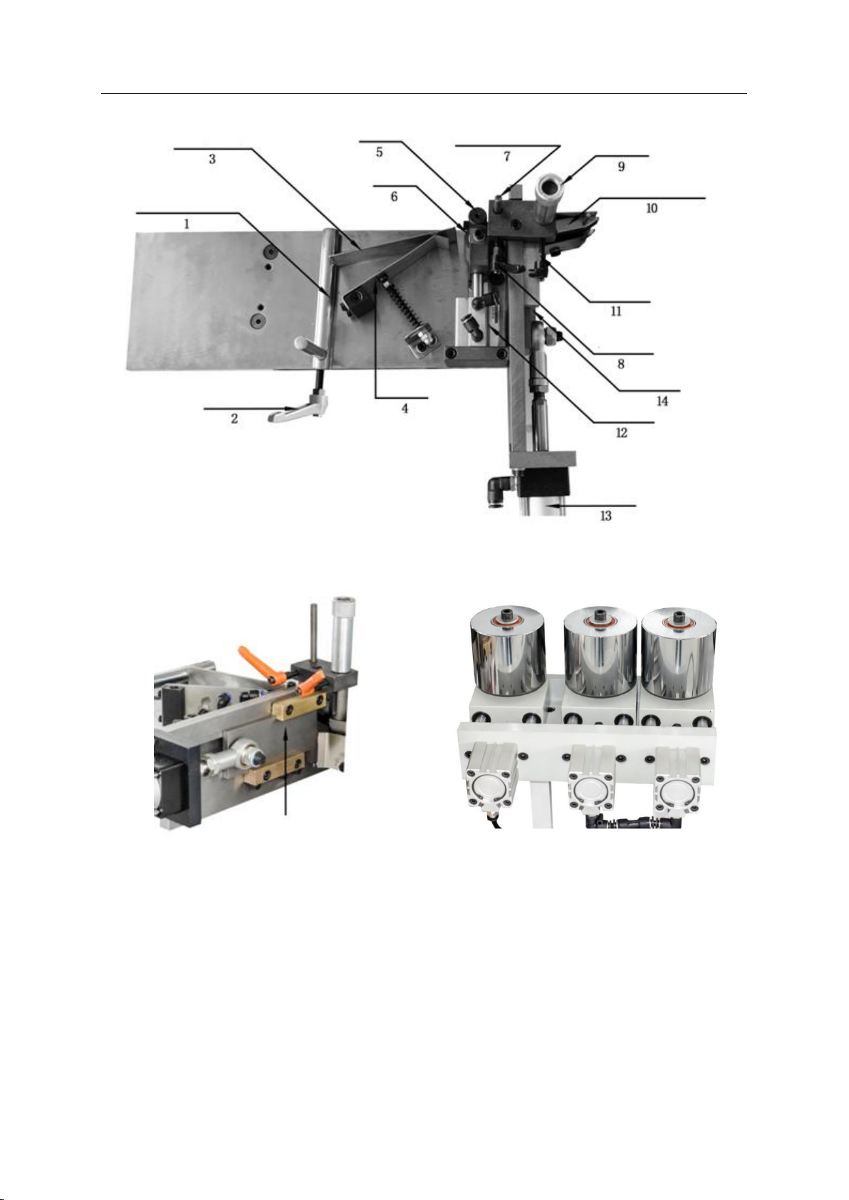
8.4.1 Installation, adjustment and sealing material automatic feeding cutting device
adjustment:
Sealing material mainly PVC, thin wood (veneer), coil.
8.4.1.1 The installation and debugging of roll banding material (Figure 6): the
thickness of 0.4-3mm roll type sealing material.
a. The roll edge belt on the belt wheel.
b. Edge banding followed by edge with a height positioning rod (1), edge band limiting
plate (3), send belt wheel (5), edge band height positioning column (7) has been to
the cutter (14) edge position.
c. According to the edge with the height and the adjustment of edge with the height of
the positioning rod (1) position, pay attention to rods with minimum position and edge
with retention of the reasonable clearance, the edge belt is not stuck also will not
shake, after a good tune, tighten the regulating handle (2).
d. According to the edge with the height and the adjustment of edge with the height of
the height positioning column (7), pay attention to and edge belt to maintain a
reasonable gap, the edge belt is not stuck also will not shake, after a good tune, tighten
the regulating handle (8).
e. According to the height of the edge with the height and the rotation of the adjusting
nut (9) to adjust the edge zone height positioning blocks (10), pay attention to and
edge band to keep the reasonable clearance, the edge belt is not stuck also will not
shake, after a good tune, tighten the regulating handle (11).
f. according to the edge thickness, adjust the pressure cylinder (12) pressure, the
tightness of the right. Note: generally do not need to adjust here, unless the edge
is thick, the pressure is too large.
g. When the edge is thick, the cutting knife can not cut off, increase the cutting
cylinder (13) pressure, until the belt cutting smoothly.
17
Figure 6
Figure 6-1 Figure 6-2
8.4.2 Edgeband other allowance adjustment
8.4.2.1 About: the workpiece edge material stretch adjustment; edgeband plate is higher
than that of unilateral height adjustment;
Note: the above two data ready standard adjustment at the factory, in the normal working
state of the equipment without reset. This data is abnormal, please consult the
after-sales service.
8.4.2.2 Melt glue temperature regulation(Figure 7):

18
Actual temperature display
Set temperature display
Temperature increase key
Temperature decrease key
Figure 7
Temperature settings: hold down the temperature increase or reduce the temperature of
the key to hold for 3 seconds, in the "set temperature display" in the number will
gradually increase or decrease, in order to set the desired temperature value.
8.4.2.3 The use of hot melt and temperature control
a. This machine is recommended to use the hot melt adhesive, German
Henkel.Dornsproduction model for KS217 or KS215 edge with hot melt adhesive, in line
with European safety standard non hazardous ingredients.
b. This machine is recommended to use the hot melt adhesive, it is recommended (and
temperature) temperature 190-200℃, sticky at best for machinery, slow running.
Note: when the heating temperature exceeds 250 ℃, hot glue decomposition failure.
c. Note: adhesive hot bath is heated to operating temperature, should be extended 10
minutes to be coated rollers to operating temperature before startup, otherwise it might
damage cots.
d. Users must according to the requirement of edge material selection of suitable
environmental and safety requirements of the hot bath gel, and according to the use
of hot melt adhesive select instructions, in order to avoid a hazard.
e. Users before the hot melt adhesive should carefully read the MSDS of hot melt adhesive,
known as its physical and chemical properties, processing methods of emergency
treatment and waste,.
8.4.3 Adjust the amount of Rubber Cots(Figure 8):
According to the label, the control direction is marked, and the handle is screwed and
transferred to the required amount of glue. Note: the addition amount of glue to add
glue pot depth three divides into two following to prevent fill out excess glue, don't
side with adhesive, prevent glue hasn't melted into the machine, the damage to the
machine. Recommended to stop the machine running, a plus glue, glue to be completely
dissolved over ten minutes before the boot can be.

19
Figure 8 Glue quantity regulating handle
8.4.4 Cylinder working pressure adjustment:
Due to changes in the edge thickness must be to pressure with a cylinder, edge
compression roller cylinder, cut take the work pressure of the cylinder to make
corresponding adjustment, value adjustment range is as follows:
Equipment
Working
pressure(Mpa)
Equipment
Working pressure
(Mpa)
Front pressure
0.2-0.3
End cutting down
0.2-0.3
Back pressure(2)
0.2-0.3
End cutting up
0.3-0.4
Cutter
0.2-0.6
Feed cylinder
0.1-0.2
Special remind: as a result of some edge belt material is more sensitive to temperature,
so when the ambient temperature is below 15 DEG C, may have an impact on the edge,
blunting effect. The method can be used to improve the environment temperature of the
tray of the tray.
8.5 End timming system
This system is used to trim the edge blunt edge plate front and rear excess sealing
material. Blunting system using high speed frequency conversion motor
0.55KW*2.200Hz.18000RPM and profiling track structure, ensures that the motor cutting
cut section of smooth and tidy. Before and after the butting motor adopts imported
cylinder, imported linear guide, ensure the motor cutting in the long-term stable and
accurate. The motor base is made of precision, which ensures the strength of the machine
tool's long-term work. Block system block and the tail two parts together. Each system
has been the standard to debug in the factory, under normal working condition has no
need to debug.
8.6 Fine trimming system
This system is for the side edge of the upper part of the lower sealing material to
repair the extra sheet edge after processing. Repair system using high speed variable
motor (0.75KW*2.200Hz.18000RPM) and profile modeling tracking structure, ensure the
motor trimming plate on the lower part of the smooth neat. Repair edge profiling at
the factory has made a precise adjustment, but in the actual production process due
to changes in the band edge and the edge plate specifications, material, may adjust
the following parts:
8.6.1 Under the regulation of finishing automatic trimming device:
Table of contents
Other SKETCHNBUILD Industrial Equipment manuals


