extronics iWAP107 User manual

iWAP107/iRFID107 Installation and Operating Manual
2
Document Number 404368(12) Refer to Extronics DDM for release status
Based on type approval document 403431
The Photograph on the front page shows the iWAP107/iRFID107 Aluminium Enclosure
version; a Stainless-Steel version is also available.
For warranty information, refer to Terms and Conditions at http://www.extronics.com
© 2022 Extronics Limited. This document is Copyright Extronics limited.
Extronics reserve the right to change this manual and its contents without notice, the latest
version applies.

iWAP107/iRFID107 Installation and Operating Manual
3
Contents
1Introduction ................................................................................................... 4
2Safety Information and Notes ........................................................................... 5
2.1 Storage of this Manual ............................................................................... 5
2.2 Special Conditions for Safe Use ................................................................... 5
2.2.1 ATEX/IECEx .............................................................................................. 5
2.3 List of Notes ............................................................................................. 5
3Installation..................................................................................................... 8
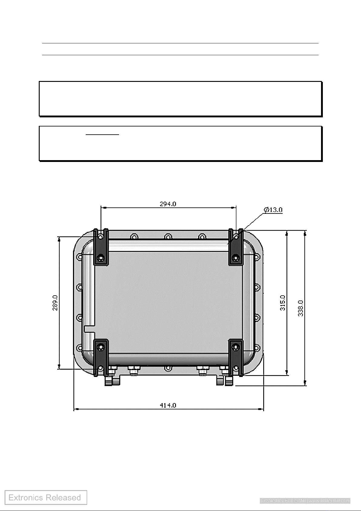
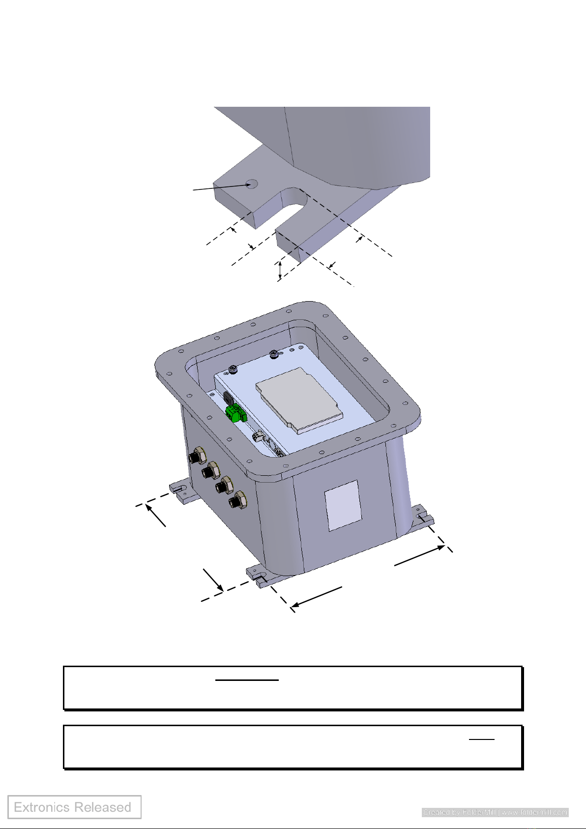
3.1 Mounting.................................................................................................. 8
3.2 Opening and Closing the Enclosure .............................................................. 9
3.2.1 Opening the Enclosure (Aluminium and Stainless Steel enclosures) ................10
3.2.2 Closing the Enclosure................................................................................11
3.3 Cable Entries ...........................................................................................11
3.3.1 Typical Cable Entries and Connections ........................................................11
3.4 Earthing ..................................................................................................12
3.4.1 iWAP107/iRFID107 earth bond point (stainless steel enclosure) .....................12
3.4.2 iWAP107/iRFID107 earth bond point (aluminium enclosure) ..........................13
3.5 Electrical Installation ................................................................................13
3.6 Power supply ...........................................................................................14
3.7 Fusing.....................................................................................................15
3.7.1 Fuse Ratings ............................................................................................15
3.7.2 Changing Fuse .........................................................................................15
3.8 External Overcurrent Protection .................................................................15
3.9 Data Connections .....................................................................................16
3.9.1 Copper Ethernet .......................................................................................16
3.9.2 Power-Over-Ethernet (POE) .......................................................................16
3.9.3 Optical Fibre ............................................................................................16
3.10 Intrinsically Safe RF Outputs......................................................................17
3.10.1 Example of RF threshold power calculation ..................................................18
3.11 Antenna Requirements..............................................................................18
3.12 Antenna Installation .................................................................................18
3.13 Prevention of Electrostatic Charging............................................................20
3.14 Additional Labels & Non-Metallic Materials ...................................................20
4Intended Purpose Usage .................................................................................21
4.1 Transportation and Storage .......................................................................21
4.2 Authorized Persons ...................................................................................21
4.3 Cleaning and Maintenance .........................................................................21
4.4 Cleaning and Maintenance Intervals............................................................21
4.5 Aggressive substances and environments ....................................................21
4.6 Exposure to external stresses ....................................................................21
5Technical Data...............................................................................................22
6Coin Cell Information......................................................................................23
7Label Drawing ...............................................................................................24
8Type Codes ...................................................................................................25
9EU Declaration of Conformity...........................................................................27

iWAP107/iRFID107 Installation and Operating Manual
4
1Introduction
The iWAP107 and iRFID107 are ATEX and IECEx approved Zone 1 Wireless Device
Enclosures with intrinsically safe RF outputs; they are designed to allow the
deployment of wireless networks in hazardous areas. The concept allows
installation of equipment from leading WLAN vendors such as Cisco, Aruba,
Aeroscout and Motorola. Each type of Access Point or RF transmitting device is
rigorously checked and tested by Extronics to ensure conformity to the latest
standards. This means that the user may select the vendor of their choice when
extending a WLAN to hazardous areas. However equipment not previously
approved will require assessment to determine its suitability.
The intrinsically safe RF outputs of the iWAP107/iRFID107 allows users to choose
any antenna for use with their wireless hardware e.g. Extronics iANT2xx range of
high quality rugged outdoor antennas. Any antennas not listed in the Extronics
range must be assessed to ensure they meet the requirements for installation of
non-electrical equipment in hazardous areas. This assessment can be provided by
Extronics or done by the user. Up to eight antennas can be utilized, allowing the
MIMO functionality of the latest compatible wireless access points to be
implemented, providing optimum coverage and maximum data throughput on
Chemical Plants, Oil Refineries or Oil & Gas Platforms. Optional features include
surge arrestors for lightning suppression in outdoor installations and single mode
or multimode fibre optic inputs to allow for extended Ethernet link distance.

iWAP107/iRFID107 Installation and Operating Manual
5
2Safety Information and Notes
2.1 Storage of this Manual
Keep this user manual safe and in the vicinity of the device. All persons required
to work on or with the device should be advised on where the manual is stored.
2.2 Special Conditions for Safe Use
2.2.1 ATEX/IECEx
1. Contact Extronics for information on the dimensions of the flameproof joints.
2. The RF output is only to be connected to an antenna suitable for the hazardous
location; refer to associated RF galvanic isolator iSOLATE501 equipment certificate
(IECEx trc 15.0015X / TRAC15ATEX0050x) or iSOLATE500 equipment certificate
(IECEx BAS 13.0064X / Baseefa13ATEX0112X), and associated instructions.
3. If the RF output connector is not intended to be connected to a cable and/or
antenna, the output connector must be capped.
4. Flamepath joints are not intended to be repaired.
5. Breather/Drain valves may be fitted providing that they are suitably ATEX/IECEx Ex
db equipment certified.
6. Cables connected to the optical input shall be installed according to IEC 60079-14
K.3 and be suitably mechanically protected.
2.3 List of Notes
The notes supplied in this chapter provide information on the following.
•Warning!
oPossible hazard to life or health.
•Caution
oPossible damage to property.
•Important
oPossible damage to enclosure, device or associated equipment.
•Information
oNotes on the optimum use of the device
Warning! Installation of the iWAP107/iRFID107 must be performed in
accordance with IEC 60079-14 and IEC 60079-25.
Maintenance and inspection must be performed in accordance
with IEC 60079-17.
Warning! Installation of the iWAP107/iRFID107 is only to be performed
by skilled electricians and instructed personnel in accordance
with national legislation.
Warning! The iWAP107/iRFID107 contains INTRINSICALLY SAFE
circuits.
Warning! The iWAP107/iRFID107 Intrinsically Safe RF output ports are
located in the positions shown in Section 3.3. Only antennas
in accordance with Section 3.11 may be connected to these
ports. Refer to Section 3.12 for antenna installation
requirements.

iWAP107/iRFID107 Installation and Operating Manual
6
Warning! The iWAP107/iRFID107 MUST be earthed. Refer to Section
[earthing] for details.
Warning! The iWAP107/iRFID107 must NOT be installed in hazardous
areas requiring Category 1, M1 or M2 equipment.
Warning! Although antennas connected to the Intrinsically Safe RF
outputs of the iWAP107/iRFID107 may be installed in
hazardous areas requiring Category 1 equipment, the
iWAP107/iRFID107 flameproof enclosure must NOT be
installed in these environments.
Warning! The iWAP107/iRFID107 flameproof enclosure must NOT be
opened when an explosive gas or dust atmosphere is present,
or when the equipment is energized.
Warning! The iWAP107/iRFID107 flameproof enclosure lid must be
secured only with the bolts supplied, and these must be
tightened to the correct torque value. See Section 3.2.2 for
details. Contact Extronics for spare bolts.
Warning! The iWAP107/iRFID107 flameproof enclosure must only be
fitted with suitably approved cable entry devices. See Section
3.3 for details.
Warning! Do not exceed the RF Threshold Power for the equipment
group in which the iWAP107/iRFID107 and its antennas are
to be installed; it must be controlled in accordance with IEC
60079-0, and must not exceed the following levels:
IIC –2W (+33dBm)
IIB –3.5W (+35.4dBm)
IA –6W (+37.7dBm)
III –6W (+37.7dBm)
See Section 0 for an example of how to calculate the RF
Threshold Power
Warning! The iWAP107/iRFID107 must not be modified in any way.
Warning! There are no user-serviceable parts below the top plate of the
iWAP107/iRFID107 - see Section 3.5 for details. Always refer
service enquiries to Extronics.

iWAP107/iRFID107 Installation and Operating Manual
7
Warning! Hazardous voltages are present within the
iWAP107/iRFID107 enclosure.
Warning! Hot surfaces may be present within the iWAP107/iRFID107
enclosure - observe the warning labels fitted.
Warning! Optical radiation hazards may be present within the
iWAP107/iRFID107 enclosure –observe the warning labels
fitted.
Warning! The iWAP107/iRFID107 may weigh up to 70Kg. Exercise care
when handling and mounting.
Warning! DO NOT lift the iWAP107/iRFID107 using the threaded
entries, N-type RF connectors or door bolts. Lift only using
suitably approved slings, fitted by suitably qualified
personnel.
Important Ensure that NO TOOLS come into contact with the flamepath
of the enclosure, as this may cause irreparable damage and
render the unit unsafe.
Important Always re-apply a thin layer of Loctite 8104 or Loxeal GS9
silicone grease to the enclosure flame paths whenever the
iWAP107/iRFID107 flameproof enclosure is opened. This is
required to maintain the IP rating of the enclosure.
Important Do not exceed the power supply parameters specified on the
iWAP107/iRFID107 external rating plate.
Important Only replace the fuse with the same value and type indicated
on the internal fuse identification label.
Important Ensure that only the correct fibre transceiver format/power is
connected to the iWAP107/iRFID107. Damage to the
iWAP107/iRFID107 fibre interface or customer equipment
may occur if the wrong format/excessive optical power is
used.
Warning! When a device is fitted with a coin cell and the coin cell is
required to be replaced, it shall only be fitted with the exact
same type coin cell as marked on the device.

iWAP107/iRFID107 Installation and Operating Manual
8
3Installation
3.1 Mounting
Warning! The iWAP107/iRFID107 stainless steel enclosure weighs
approximately 70Kg. Exercise care when handling, and use
suitable mounting points and structures. Mount the enclosure
ONLY using the mounting points shown.
Warning! DO NOT lift the iWAP107/iRFID107 using the threaded
entries, N-type RF connectors or door bolts. Lift only using
suitably approved slings, fitted by suitably qualified
personnel.
Mount the iWAP107/iRFID107 enclosure to a suitable structure, using the mounting points
shown.
Figure 1: Aluminium Enclosure Mounting Dimensions

iWAP107/iRFID107 Installation and Operating Manual
9
3.2 Opening and Closing the Enclosure
Important Ensure that NO TOOLS come into contact with the flamepath
of the enclosure, as this may cause irreparable damage and
render the unit unsafe.
Warning! The iWAP107/iRFID107 flameproof enclosure must NOT be
opened when an explosive gas or dust atmosphere is present,
or when the equipment is energized.
13mm
21.5mm
10mm
M5 threaded
earth point
294mm
between centres
290mm
between centres
Figure 1: iWAP107/iRFID107 Stainless Steel Enclosure Mounting Points

iWAP107/iRFID107 Installation and Operating Manual
10
Warning! The iWAP107/iRFID107 flameproof enclosure lid must be
secured only with the bolts supplied, and these must be
tightened to the correct torque value. Contact Extronics for
spare bolts.
Important Always re-apply a thin layer of Loctite 8104 or Loxeal GS9
silicone grease to the enclosure flame paths whenever the
iWAP107/iRFID107 flameproof enclosure is opened. This is
required to maintain the IP rating of the enclosure.
3.2.1 Opening the Enclosure (Aluminium and Stainless Steel enclosures)
The flamepaths of the iWAP107/iRFID107 enclosure are supplied with grease applied to
protect them. This can make the enclosure lid difficult to open as the grease can cause it
to stick. Extronics recommend the use of a double suction lifter. This tool is included with
iWAP107/iRFID107 deliveries and is available from Extronics or hardware and builders
supply stores. Extronics recommend using a lifter that has a working load of 50kg
minimum and approximate dimensions 300mm x 120mm
•Remove all bolts, using a wrench with an 8mm hex head. Store the bolts carefully
to avoid damage or loss.
•Attach the suction lifter as per the instructions provided and release the door.
Note, moving the door side to side may help in loosening the grease
Figure 2: Opening iWAP107/iRFID107 Enclosure with Suction Lifter

iWAP107/iRFID107 Installation and Operating Manual
11
3.2.2 Closing the Enclosure
•Check that the correct grease (Loctite 8104 or Loxeal GS9) has been applied to the
flame-path, and that it is free of damage.
•Check all bolts are the correct type and free from damage.
•Re-insert the bolts and hand-tighten only.
•Using a torque wrench fitted with an 8mm hex head, tighten the bolts in opposite
corners of the box, then work around the box. Use the following maximum torque.
3.2.2.1 Lid Bolt Torques
Enclosure material
Maximum Bolt Torque
Aluminium
20Nm
Stainless Steel
44Nm
Table 1: Enclosure Bolt Torques
3.3 Cable Entries
Warning! The iWAP107/iRFID107 flameproof enclosure must only be
fitted with suitably approved cable entry devices.
Warning! The iWAP107/iRFID107 protective plastic transport caps
fitted to all threaded cable entries MUST be replaced with
suitably certified cable glands or stopping plugs before
installation in a hazardous area.
Warning! Any iSOLATE-CT RF connector transits fitted to the
iWAP107/iRFID107 must NOT be loosened or removed by the
user under any circumstances, as their flameproof protection
may be damaged by this.
3.3.1 Typical Cable Entries and Connections
A typical iWAP107/iRFID107 enclosure is supplied with entries and connectors as shown in
Figure 3.
•Connections A-D are INTRINSICALLY SAFE outputs providing galvanically isolated
RF signals (see Section 17 for details), carried on conventional 50Ω impedance N-
type female connections. The N-type connections are the front part of the iSOLATE-
CT devices which transit through the flameproof wall of the enclosure and are
approved as part of the iWAP107/iRFID107 ATEX/IECEx certification.
•Entries E and F are M20 x 1.5 –6H threaded Ex d entries. Entry F is for the power
supply, entry E for the data connection.
•The position and configuration of cable entries and connections can vary depending
on the iWAP107/iRFID107 ordered. Check with Extronics for more information if
required.

iWAP107/iRFID107 Installation and Operating Manual
12
3.4 Earthing
Warning! The iWAP107/iRFID107 MUST be earthed. It must be
connected to the plant earth system using at least one of the
external bonding points, using a minimum 4mm2conductor.
The earth cable must be installed in accordance with the
requirements of IEC 60079-14.
Warning! The iWAP107/iRFID107 enclosure door earth bond must not
be removed.
Warning! The iWAP107/iRFID107 internal power input connector has an
earth connection, which must be terminated to the protective
earth conductor of the incoming power supply.
3.4.1 iWAP107/iRFID107 earth bond point (stainless steel enclosure)
There is an M5 threaded earth bond point on each of the 4 enclosure feet.
Figure 3: iWAP107/iRFID107 Aluminium Enclosure External Entries and Connections
Antenna layout “B4” in the example shown
Figure 4: iWAP107/iRFID107 Stainless Steel Enclosure External Earth Bond Points

iWAP107/iRFID107 Installation and Operating Manual
13
3.4.2 iWAP107/iRFID107 earth bond point (aluminium enclosure)
3.5 Electrical Installation
Important Do not exceed the power supply parameters specified on the
iWAP107/iRFID107 external rating plate.
Important Only replace the fuse with the same value and type indicated
on the internal fuse identification label.
Designator
Purpose
Comments
Figure 5: iWAP107/iRFID107 Aluminium Enclosure Earth Bond Point
A
B
C
D
E
F
Figure 6: iWAP107/iRFID107 Internal Connections Showing All Options

iWAP107/iRFID107 Installation and Operating Manual
14
A
Fuse Holder
Contains 1 active fuse and
1 spare. Not fitted on POE
version. See Section 3.7
B
Power input
Mains (L,N,E) or DC (+,-,E)
input, dependent on
product configuration. Not
fitted on POE version. See
Section 3.6 for details.
C
Fibre input
This can be single mode or
multimode fibre, or
replaced by a blanking
plate, depending on
product options. See
Section 3.9.3 for details
D
Ethernet input
100/1000 BaseT CAT6A
data connection. It may
also be replaced by a
blanking plate, depending
on product options. See
Section 3.9.1 for details
E
Console port
This is a serial console port
for the installed wireless
device. Refer to wireless
device manual for
connection details
F
Fibre splice tray
This is a 12-way fibre
splice tray, only fitted when
the fibre option is selected.
Table 2: iWAP107/iRFID107 Internal Connection/Features
3.6 Power supply
Important The iWAP107/iRFID107 may be powered from a number of
different power sources, depending on its configuration. Refer
to the rating plate of the unit supplied for details.
The mains
power connection is made with a 2-part screw-terminal connector (supplied), the plug part
Figure 7: iWAP107/iRFID107 Mains Power Connection
LIVE
NEUTRAL
EARTH
Use 3.5mm x 0.6mm
slotted screwdriver,
0.5-0.6Nm

iWAP107/iRFID107 Installation and Operating Manual
15
is Phoenix Contact 1804917, and spare plugs can also be supplied by Extronics. It has a
minimum tightening torque of 0.5Nm, a maximum of 0.6Nm, and requires a 3.5mm x
0.6mm slotted screwdriver.
Wire Type
Minimum Cross
Sectional Area
Maximum Cross Sectional
Area
Single Solid Core
0.2mm2
4mm2
Single Stranded Wire
0.2mm2
4mm2
Single Stranded Wire, With
Ferrule With/Without
Sleeve
0.25mm2
4mm2
2 Solid Conductors With
Same Cross Section
0.2mm2
2mm2
2 Stranded Conductors
With Same Cross Section
0.2mm2
1.5mm2
2 Stranded Conductors
With Same Cross Section,
With Ferrules Without
Sleeves
0.25mm2
1.5mm2
Table 3: iWAP107/iRFID107 Power Connector Wire Gauges
3.7 Fusing
3.7.1 Fuse Ratings
Important Only replace the fuse with the correct type, having established
the reason for the fuse blowing.
The iWAP107/iRFID107 is fitted with a single fuse on the Live circuit, of either a 1A or 2A,
depending its configuration. The fuse requirement for the specific model supplied is written
on the top plate next to the fuse holder.
The iWAP107/iRFID107 contains surge suppression and filtering devices which may cause
the fuse to blow if the unit is subjected to power surges or transients.
Replacement fuses should be either 1 or 2A Time-lag 20mm x 5mm HRC Fuses, rated at
250VAC, 1500A Interrupt Rating, for example Littelfuse 0215001.MXP or 0215002.MXP.
3.7.2 Changing Fuse
See Figure 8 for access to Fuse. The fuse holder also carries a spare fuse for convenience.
3.8 External Overcurrent Protection
The iWAP107/iRFID107 should be installed on a circuit with a double-pole circuit breaker
Push Down To
Open
Active Fuse
Spare Fuse
Push Up
and Lock to
Close and
Make Circuit
Figure 8: Fuse Access

iWAP107/iRFID107 Installation and Operating Manual
16
of a maximum of 25A. This is the maximum current rating of the smallest internal chassis
earth bond in accordance with EN60950-1 2.6.3.3. Refer to Extronics if it becomes
necessary to exceed this rating.
3.9 Data Connections
3.9.1 Copper Ethernet
Information Check that the line speed of the switch port to which the
iWAP107/iRFID107 is connected matches the
iWAP107/iRFID107 port configuration, otherwise
communication may not be established.
If Copper Ethernet is specified, this will be terminated in a standard CAT5E RJ45 Socket on
the front plate of the iWAP107/iRFID107, Position D in Figure 6. Typically the interface will
be an IEEE 10/100/1000BaseT format, but this is dependent on the access point installed.
Terminate the RJ45 plug as follows (EIA 568B standard):
3.9.2 Power-Over-Ethernet (POE)
If Power-Over-Ethernet (POE) is used, the format will depend on the access point installed
in the iWAP107/iRFID107. Ensure that the correct Power Sourcing Equipment (PSE) is
used. Connect the RJ45 cable per Section 3.9.1.
3.9.3 Optical Fibre
Warning! Optical radiation hazards may be present within the
iWAP107/iRFID107 enclosure –observe the warning labels
fitted.
Important Ensure that only the correct fibre transceiver format/power is
connected to the iWAP107/iRFID107. Damage to the
iWAP107/iRFID107 fibre interface or customer equipment
may occur if the wrong format/excessive optical power is
used.
The iWAP107/iRFID107 optical fibre format may be any of the following, refer to product
option code #5 for details. Other optical formats are available on request.
Option
#5
Fibre Format
Connection
Transmitter
Power
Receiver
Sensitivity
Max
Receiver
Input
Without
Wavelength
Typical
Range
Figure 9: RJ45 CAT5E EIA 568B Plug Wiring

iWAP107/iRFID107 Installation and Operating Manual
17
Damage
SX
1000Base-SX
LC Duplex
Multimode
62/125µm or
50/125µm
-1 to - 9dBm
(50/125µm)
-19dBm
-1dBm
850nm
550m
(50/125µm)
LX
1000Base-LX
LC Duplex Single
Mode 9/125 µm
-3 to -9.5dBm
-20dBm
-3dBm
1310nm
20km
Table 4: Fibre Formats
3.10 Intrinsically Safe RF Outputs
Warning! The iWAP107/iRFID107 Intrinsically Safe RF output ports are
located in the positions shown in Section 3.3. Only antennas
in accordance with Section 3.11 may be connected to these
ports. Refer to Section 3.12 for antenna installation
requirements.
Warning! Although antennas connected to the Intrinsically Safe RF
outputs of the iWAP107/iRFID107 may be installed in a
hazardous areas requiring Category 1 equipment, the
iWAP107/iRFID107 flameproof enclosure must NOT be
installed in these environments.
Warning! Do not exceed the RF Threshold Power for the equipment
group in which the iWAP107/iRFID107 and its antennas are to
be installed; it must be controlled in accordance with
IEC 60079-0, and must not exceed the following levels:
IIC –2W (+33dBm)
IIB –3.5W (+35.4dBm)
IIA –6W (+37.7dBm)
III –6W (+37.7dBm)
The RF outputs of the iWAP107/iRFID107 are approved as:
Ex ia IIC Ga
Ex ia IIIC Da
Um= 253Vr.m.s
Refer to Figure 3 for location of Intrinsically Safe RF outputs of
iWAP107/iRFID107 with “B4” layout as example

iWAP107/iRFID107 Installation and Operating Manual
18
3.10.1 Example of RF threshold power calculation
The following example shows how the RF threshold power may be calculated:
Maximum transmitter output power (from transmitter datasheet) = 20dBm (100mW)
Coaxial cable loss = 2dB
Antenna gain = 5dBi
Threshold power = 20dBm –2dB + 5dBi
Threshold power = 23dBm (200mW)
Warning! Due to the typical maximum transmit power of UHF readers
(in the case of iRFID107), customers may need to install
attenuators or excess lengths of RF cable to comply with
maximum RF thresholds. Contact Extronics for more
information.
3.11 Antenna Requirements
Antennas connected to the iWAP107/iRFID107 Intrinsically Safe RF outputs must be
assessed as ‘simple apparatus’ in accordance with IEC 60079-11. Antennas supplied by
Extronics for use with the iWAP107/iRFID107 already meet these requirements. It is
possible to assess other antennas for this purpose, contact Extronics for details.
3.12 Antenna Installation
Antennas approved by Extronics for use with the iWAP107/iRFID107 may either be fitted
directly to the RF connectors of the iWAP107/iRFID107, or via a length of coaxial cable.
If antennas are sited remotely from the iWAP107/iRFID107 flameproof enclosure, any
metallic parts of the antennas must be isolated from earth by > 500Vr.m.s, to prevent
hazardous earth currents from flowing in the coaxial cable.

iWAP107/iRFID107 Installation and Operating Manual
20
3.13 Prevention of Electrostatic Charging
The iWAP107/iRFID107 enclosure can build up electrostatic charge on its surfaces, so the
following steps are to be followed to reduce static charge build up:
Static charge build up should be reduced by:
•Connecting the enclosure to a suitable earth point
•Cleaning off surface dust using a damp cloth
•Not installing into areas where high airflow can occur
3.14 Additional Labels & Non-Metallic Materials
Additional labels may be fitted to the enclosure. Label material may be stainless steel or
any other non-metallic material. To prevent an electro-static risk, non-metallic materials
must only be cleaned with a damp cloth.
If non-metallic materials are used, consideration should be given to the following:
•Control of environmental humidity to minimise the generation of static electricity.
•Protection from direct airflow causing a charge transfer.
•Touch with an insulation object.
•Means to continuously drain off electrostatic charges.
Refer to IEC 60079 Part 0 for further information
Other manuals for iWAP107
1
This manual suits for next models
1
Table of contents
Other extronics Industrial Equipment manuals