Hardinge Bridgeport EZ Vision User manual
INSTALLATION, MAINTENANCE,
AND PARTS LIST
EZ Vision™
Automated Milling Machines
Revised: March 28, 2008
Manual No. M-477A Litho in U.S.A.
Part No. M A-0009500-0477 May, 2007
TP7441

Information in this manual is subject to change without notice.
This manual covers the installation, maintenance, and parts list for EZ Vision™au
-
tomated milling machines equipped with the DC150 motion control system.
In no event will Hardinge Inc. be responsible for indirect or consequential damage
resulting from the use or application of the information in this manual.
Reproduction of this manual, in whole or in part, without written permission of
Hardinge Inc. is prohibited.
CONVENTIONS USED IN THIS MANUAL
- WARNINGS -
Warnings must be followed carefully to avoid the possibility of personal in-
jury or damage to the machine, tooling, or workpiece.
- CAUTIONS -
Cautions must be followed carefully to avoid the possibility of damage to the
machine, tooling, or workpiece.
- NOTES -
Notes contain supplemental information.
- NOTICE -
Bridgeport is a registered trademark of Hardinge Inc.
© 2007, Hardinge Inc. M-477A

READ COMPLETE INSTRUCTIONS CAREFULLY BEFORE OPERATING MACHINE
When this instruction book was printed, the information given was current. However, since we are
constantly improving the design of our machine tools, it is possible that the illustrations and
descriptions may vary from the machine you received.
- WARNING -
Occupational Health and Safety Administration (OSHA) Hazard Communica-
tion Standard 1910.1200, effective May 25, 1986, and various state “employee
right-to-know” laws require that information regarding chemicals used with
this equipment be supplied to you. Refer to the applicable section of the Ma-
terial Safety Data Sheets supplied with your machine when handling, storing,
or disposing of chemicals.
HARDINGE SAFETY RECOMMENDATIONS
Your Hardinge machine is designed and built for maximum ease and safety of operation.
However, some previously accepted shop practices may not reflect current safety regulations and
procedures, and should be re-examined to insure compliance with the current safety and health
standards.
Hardinge Inc. recommends that all shop supervisors, maintenance personnel, and machine tool
operators be advised of the importance of safe maintenance, setup, and operation of Hardinge-built
equipment. Our recommendations are described below. BE SURE TO READ THESE SAFETY
RECOMMENDATIONS BEFORE PROCEEDING ANY FURTHER.
READ THE APPROPRIATE MANUAL AND/OR INSTRUCTIONS before attempting opera-
tion or maintenance of the machine. Make certain that you understand all instructions.
DON’T ALLOW the operation or repair of equipment by untrained personnel.
CONSULT YOUR SUPERVISOR when in doubt as to the correct way to do a job.
WEAR SAFETY GLASSES AND PROPER FOOT PROTECTION at all times. When neces-
sary, wear a respirator, helmet, gloves, and ear muffs or plugs.
DON’T OPERATE EQUIPMENT unless proper maintenance has been regularly performed
and the equipment is known to be in good working order.
WARNING OR INSTRUCTION TAGS are mounted on the machine for your safety and in-
formation. Do not remove them.
DON’T ALTER THE MACHINE to bypass any interlock, overload, disconnect, or other
safety device.
DON’T OPERATE EQUIPMENT if unusual or excessive heat, noise, smoke, or vibration
occurs. Report any excessive or unusual vibration, sounds, smoke or heat as well as any
damaged parts.
MAKE CERTAIN that the equipment is properly grounded. Consult National Electric Code
and all local codes.
M-477A i

DISCONNECT MAIN ELECTRICAL POWER before attempting any repair or maintenance.
ALLOW ONLY AUTHORIZED PERSONNEL to have access to enclosures containing elec-
trical equipment.
DON’T REACH into any control or power case area unless electrical power is OFF.
DON’T TOUCH ELECTRICAL EQUIPMENT when hands are wet or when standing on a
wet surface.
REPLACE BLOWN FUSES with fuses of the same size and type as originally furnished.
ASCERTAIN AND CORRECT the cause of a shutdown caused by overload heaters before
restarting the machine.
KEEP THE AREA AROUND THE MACHINE well lighted and dry.
KEEP CHEMICALS AND FLAMMABLE MATERIALS away from electrical or operating
equipment.
HAVE THE CORRECT TYPE OF FIRE EXTINGUISHER handy when machining combusti-
ble material and keep chips clear of the work area.
DON’T USE a toxic or flammable substance as a solvent cleaner or coolant.
MAKE CERTAIN THAT PROPER GUARDING is in place.
MAKE SURE chucks, closers, fixture plates, and all other spindle-mounted work-holding
devices are properly mounted and secured before starting the machine.
MAKE CERTAIN all tools are securely clamped in position before starting the machine.
REMOVE ANY LOOSE PARTS OR TOOLS left on machine or in the work area before op-
erating the machine. Always check the machine and work area for loose tools and parts
especially after work has been completed by maintenance personnel.
REMOVE CHUCK WRENCHES before starting the machine.
BEFORE PRESSING THE CYCLE START PUSH BUTTON, make certain that proper func-
tions are programmed and that all controls are set in the desired modes.
KNOW WHERE ALL STOP push buttons are located in case of an emergency.
CHECK THE LUBRICATION OIL LEVEL and the status of the indicator lights before oper-
ating the machine.
MAKE CERTAIN that all guards are in good condition and are functioning properly before
operating the machine.
INSPECT ALL SAFETY DEVICES AND GUARDS to make certain that they are in good
condition and are functioning properly before the cycle is started.
CHECK THE POSITION of the tooling before pressing the Cycle Start push button.
USE PROPER Point-of-Operation safeguarding.
CHECK SETUP, TOOLING, AND SECURITY OF THE WORKPIECE if the machine has
been OFF for any length of time.
ii M-477A

DRY CYCLE a new setup to check for programming errors.
MAKE CERTAIN that you are clear of any “pinch points” created by moving slides before
starting the machine.
DON’T OPERATE any equipment while any part of the body is in the proximity of a poten-
tially hazardous area.
KEEP ALL PARTS OF YOUR BODY AWAY from moving parts (belts, cutters, gears, and
others).
DON’T REMOVE CHIPS with hands. Use a hook or similar device and make certain that
all machine movements have ceased.
BE CAREFUL of sharp edges when handling a newly machined workpiece.
DON’T REMOVE OR LOAD a workpiece while any part of the machine is in motion.
DON’T OPERATE ANY MACHINE while wearing rings, watches, jewelry, loose clothing,
neckties, or long hair not contained by a net or shop cap.
NEVER OPERATE A MACHINE after taking strong medication, using non-prescription
drugs, or consuming alcoholic beverages.
DON’T ADJUST tooling or coolant hoses while the machine is running.
DON’T LEAVE tools, work pieces, or other loose items where they can come in contact
with a moving component of the machine.
DON’T CHECK finishes or dimensions of workpiece near running spindle or moving slides.
DON’T JOG SPINDLE in either direction when checking thread with a thread gage.
DON’T ATTEMPT to brake or slow the machine with hands or any makeshift device.
ANY ATTACHMENT, TOOL, OR MACHINE MODIFICATION not obtained from Hardinge
Inc. must be reviewed by a qualified safety engineer before installation.
USE CAUTION around exposed mechanisms and tooling, especially when setting up. Be
CAREFUL of sharp edges on tools.
DON’T USE worn or defective hand tools. Use the proper size and type for the job being
performed.
USE ONLY a soft-faced hammer on tooling and fixtures.
DON’T USE worn or broken tooling on machine.
MAKE CERTAIN that all tool or workpiece mounting surfaces are clean before mounting
tools.
INSPECT ALL CHUCKING DEVICES daily to make certain that they are in good operating
condition. Replace any defective chuck before operating the machine.
USE MAXIMUM ALLOWABLE gripping pressure on the chuck. Consider weight, shape,
and balance of the workpiece.
USE LIGHTER THAN NORMAL feedrates and depth of cut when machining a workpiece
diameter that is larger than the gripping diameter.
DON’T EXCEED the rated capacity of the machine.
DON’T LEAVE the machine unattended while it is operating.
M-477A iii

DON’T CLEAN the machine with an air hose.
KEEP TOTE PANS a safe distance from the machine. Don’t overfill the tote pans.
UNLESS OTHERWISE NOTED, all operating and maintenance procedures are to be per-
formed by one person. To avoid injury to yourself and others, be sure that all personnel are
clear of the machine before beginning operation.
FOR YOUR PROTECTION - WORK SAFELY.
Some of these precautions and other safety precautions are discussed in the American National
Standards Institute Standard entitled Safety Requirements for the Construction, Care, and Use of
Drilling, Milling, and Boring Machines (ANSI B11.8-1983).
This publication is available from:
American National Standards Institute
25 West 43rd Street, 4th floor
New York, NY 10036
Safeguarding for protection at the point of operation can only be designed and constructed when
the parameters of the particular operation have been determined. As a result, ANSI B11.8-1983,
Section 5.1, states that “it shall be the responsibility of the employer to provide, and ensure the use
of, a guard, guarding device, awareness barrier, awareness device, or shield...”
To assist machine users in designing point of operation safeguarding for their specific machine
applications the Occupational Safety and Health Administration has published a booklet entitled
Concepts and Techniques of Machine Safeguarding (O.S.H.A. Publication Number 3067).
This publication is available from:
The Publication Office – O.S.H.A.
U.S. Department of Labor
200 Constitution Avenue, NW
Washington, D.C. 20210
The general purpose point of operation shield provided with this machine and shown in certain
illustrations throughout this manual may not be appropriate and cannot be utilized for all possible
applications of the machine. Use additional or alternate safeguarding where this shield is not
appropriate or cannot be utilized. Note that for purposes of display, the shield has been removed in
certain other illustrations in this manual.
- NOTE -
Any unauthorized changing of control parameters is not permitted. Hardinge Inc.
will not accept any liability whatsoever for the alteration of any set parameters to
those programmed at installation.
-NOTE -
DO NOT attempt disassembly or removal of major components without first con-
tacting the Hardinge Inc. service department for proper procedures.
iv M-477A

Table of Contents
CHAPTER 1 - MACHINE SPECIFICATIONS
Basic Components................................1-1
Physical Specifications ..............................1-2
Travel ....................................1-2
Table ....................................1-2
Space and Weight ..............................1-2
Spindle ...................................1-2
Ballscrews ..................................1-3
Positioning ..................................1-3
Machine and Control Performance .......................1-3
Power ....................................1-3
Principal Dimensions...............................1-4
Machine Dimensions ...............................1-5
Front View ..................................1-5
Side View ..................................1-6
Head Specifications ...............................1-7
Head Dimensions ................................1-8
Spindle Specifications ..............................1-9
CHAPTER 2 - INSTALLATION
Uncrating ....................................2-1
Shortages ....................................2-1
Cleaning and Lubricating .............................2-1
Machine Floor Plan ...............................2-2
Lifting the Machine................................2-3
Placing Machine on a Solid Foundation ......................2-4
Control Pendant Installation ...........................2-6
Power Case Inspection..............................2-8
Connect the Electrical Power ...........................2-9
Protective Ground ................................2-10
Prestart Checks .................................2-11
Start-Up Checklist ................................2-12
Head Tram ...................................2-13
X Axis Tram Adjustment ...........................2-14
Y Axis Tram Adjustment ...........................2-15
M-477A v

CHAPTER 3 - PREVENTIVE MAINTENANCE
Preventive Maintenance Schedule ........................3-1
Dry Cutting ...................................3-2
Equipment and Supplies .............................3-2
Maintenance Procedures .............................3-3
Daily.....................................3-3
Check the Automatic Lubrication System Oil Level ..............3-3
Clean the Machine Ways .........................3-3
Weekly ...................................3-3
Clean the Way Covers and Lightly Oil....................3-3
Check the Coolant Level ..........................3-3
Check the Flood Coolant..........................3-3
Apply Oil to the Drawbar ..........................3-4
Apply Oil to the Spindle ..........................3-4
Monthly ...................................3-5
Clean the Machine Exterior, Clear Air Intakes, and Exhausts .........3-5
Clean the Air Filters ............................3-5
Clean the Interior of the Power Case ....................3-5
Semi-Annually ................................3-6
Check the Pneumatic Regulator System Bowl ................3-6
Drain and Clean the Pneumatic Filter Bowls .................3-6
Check the Spindle Motor for Dirt ......................3-6
Check the Spindle Drive Belt for Dirt and Wear ...............3-7
Grease the Vari-Drive ...........................3-7
As Specified on Lubrication Tag ........................3-7
As Required .................................3-7
CHAPTER 4 - MAINTENANCE
Spindle Drive Motor Removal ...........................4-1
Drive Belt Replacement .............................4-2
Timing Belt Replacement .............................4-3
Brake Shoe Replacement ............................4-4
Micro Feed Trip Assembly and Quill Removal ...................4-5
Balance Spring Replacement ...........................4-6
Feed Trip Adjustment ..............................4-7
Collet Aligning Screw Replacement ........................4-8
Table Gib Adjustment ..............................4-9
Saddle Gib Adjustment..............................4-11
Knee Gib Adjustment ..............................4-13
vi M-477A

CHAPTER 5 - AUTOMATIC LUBRICATION SYSTEM
Introduction ...................................5-1
Overview ....................................5-1
Oil Viscosity Range ...............................5-1
Approved Lubricants ...............................5-1
Lubricator Unit..................................5-2
Maintenance .................................5-2
Motor Replacement ..............................5-2
Operation ..................................5-3
Lubricator Pump..............................5-3
Adjusting the Oil Discharge Volume Per Cycle................5-3
Discharge Pressure ............................5-3
Lubricator Filter................................5-4
Liquid Level Sensor..............................5-4
Lubrication Oil Specification ...........................5-5
General Description..............................5-5
Uses.....................................5-5
Specification Table ..............................5-5
CHAPTER 6 - SAFETY GUARD INSTALLATION
Introduction ...................................6-1
Installation Procedures ..............................6-2
Machines with R-8 Spindle ..........................6-2
Machines with Erickson #30 or Universal #200 Quick-Change Spindle ......6-3
Erickson #30 Quick-Change Spindle ....................6-3
Universal #200 Quick-Change Spindle ...................6-3
Component Lists.................................6-4
R-8 Safety Guard Assembly ..........................6-4
Quick-Change Safety Guard Assembly .....................6-5
CHAPTER 7 - PARTS LISTINGS
Head Top Housing................................7-1
Head Back Gear.................................7-4
Head Lower Housing...............................7-8
Basic Machine..................................7-14
Left End of X Axis Ballscrew ...........................7-18
Right End of X Axis Ballscrew ..........................7-20
Ballscrew with Nut Block .............................7-21
Y Axis Drive with Nutblock ............................7-22
3rd Axis Option .................................7-24
Operator Pendant ................................7-26
Power Case, External View............................7-27
Power Case, Internal View ............................7-28
Power Case Terminal Strips ...........................7-29
Operator Pendant and Power Case Component List ................7-30
M-477A vii

- NOTES -
viii M-477A
CHAPTER 1 - MACHINE SPECIFICATIONS
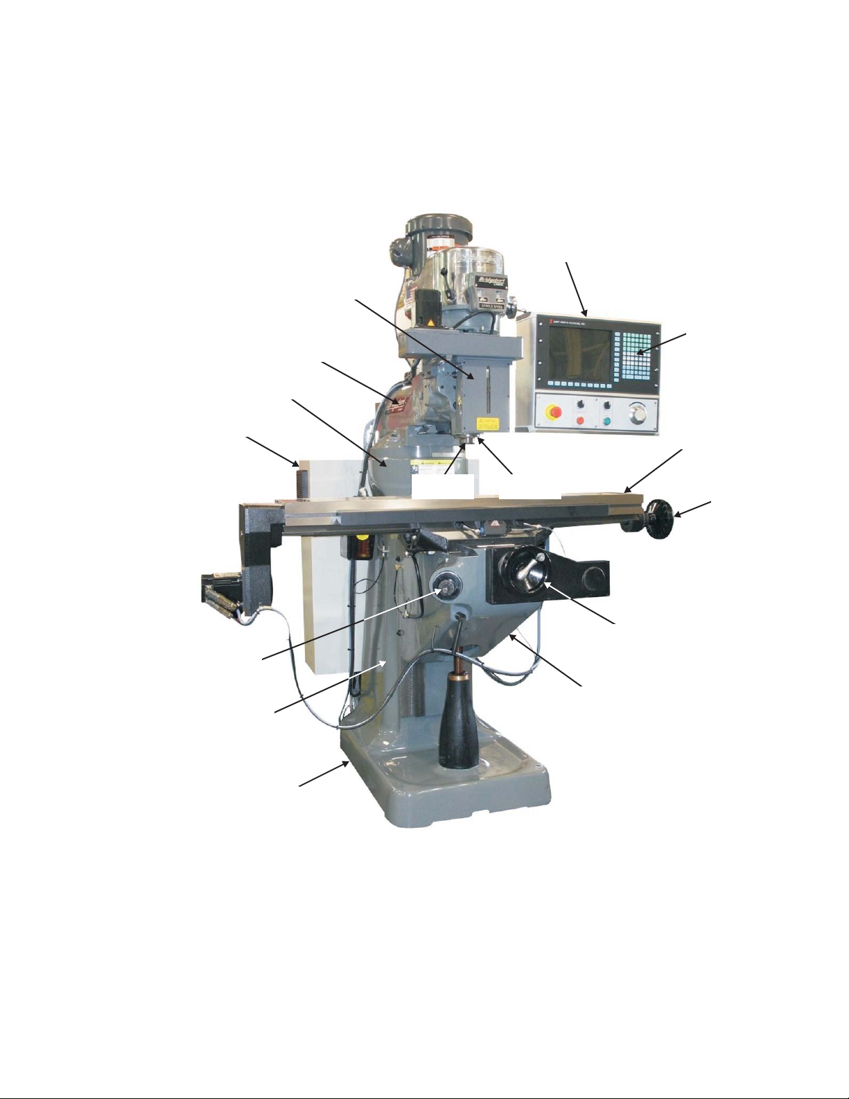
BASIC COMPONENTS
M-477A 1-1
Figure 1.1 - 3 Axis Milling Machine
TP6891
Control Unit
Ram
Z Axis Ball Screw Housing
(3 Axis Machines Only)
Turret
Electrical Control Box
Keypad
Table
X-Axis
Handwheel
Y-Axis
Handwheel
Knee
Knee Crank
(Handle Removed)
Column
Base
QuillSpindle

PHYSICAL SPECIFICATIONS
TRAVEL
Table travel (X axis) 30 in. 762 mm
Saddle travel (Y axis) 12 in. 305 mm
Quill travel 5 in. 127 mm
Quill travel w/3rd axis 4.5 in. 114 mm
Knee travel* (Z axis) 16 in. 406 mm
Ram travel 12 in. 305 mm
Throat distance (min.) 6.75 in. 171 mm
Throat distance (max.) 18.75 in. 476 mm
Table to spindle nose gage line (min.) 2.5 in. 64 mm
Table to spindle nose gage line (max.) 18.25 in. 463 mm
TABLE
Overall size 48 x 9 in. 1219 x 229 mm
Working surface 48 x 9 in. 1219 x 229 mm
Height above floor (max.) 47.4 in. 1204 mm
Maximum uniform load 300 lbs. 136 kg
T-slots 3 @ 2.5 in. Cntr 64 mm
T-slot size .625 in. 16 mm
SPACE AND WEIGHT
Floor area (door open) 8.2 x 7.3 ft. 2.5 x 2.2 m
Floor area (door closed) 8.2 x 5.3 ft. 2.5 x 1.6 m
Height 6.8 ft. 2.1 m
Net weight 2340 lbs. 1061 kg
Shipping weight 2900 lbs. 1315 kg
SPINDLE
AC spindle motor rating (continuous) 2 hp 1.5 kw
Power rating 3 hp 2.2 kw
Duty cycle 30 min. duty rated
Spindle speed Hi 500 – 4200 rpm
Spindle speed Low 60 – 500 rpm
Spindle diameter 1.875 in. 48 mm
Quill diameter 3.375 in. 86 mm
Standard Spindle Taper
Spindle taper R-8
Tooling R-8 collets
Optional Spindle Taper
Spindle Taper #30 ISO
Tool Holder Erickson Quickchange #30 ISO
Spindle Taper #200 Universal
Tool Holder Universal #200 Kwik switch
1-2 M-477A

BALLSCREWS
Diameter 1.25 in. 32 mm
Pitch 0.200 in. 5.08 mm
POSITIONING
Auto (X,Y) 100 ipm 2540 mm/min.
Manual (X,Y) 100 ipm 2540 mm/min.
Feedrate range (X,Y) 0.1 - 100 ipm 2 - 2540 mm/min.
Minimum increment 0.0001 in. 0.003 mm
MACHINE AND CONTROL PERFORMANCE
Positioning accuracy over saddle ± 0.001 in. 0.025 mm
Positioning repeatability over saddle ± 0.0008 in. 0.02 mm
Input resolution 0.0001 in. 0.003 mm
Servo resolution 0.0001 in. 0.003 mm
Display resolution 0.0001 in. 0.003 mm
BPC2M PC Control system
Full 3-axis Digital Readout
Simultaneous 2 axis linear or 2 axis circular interpolation
10.5-inch color conversational display
Absolute and incremental programming
Automatic corner rounding
Mathematical help modes
Powerful canned cycles for machining arcs, diagonals, circles, bolt hole patterns,
pocket milling and more
Cutter diameter compensation
English/metric conversion
1000 block program storage
Disk storage: (standard) 3.5 in. diskette, HD 1.44 Mb (12,000 ft.)
8MB PC Flashdisk
Maintenance, diagnostic and program error message display
Part program loading: RS-232 bi-directional communication link
Input/Output: 1 RS-232 serial port
Maintenance: Diagnostic routines embedded in system
POWER
Input power: 208/230/460 volts 3 phase, 50/60 cycles
Power capacity: 4kVA
M-477A 1-3
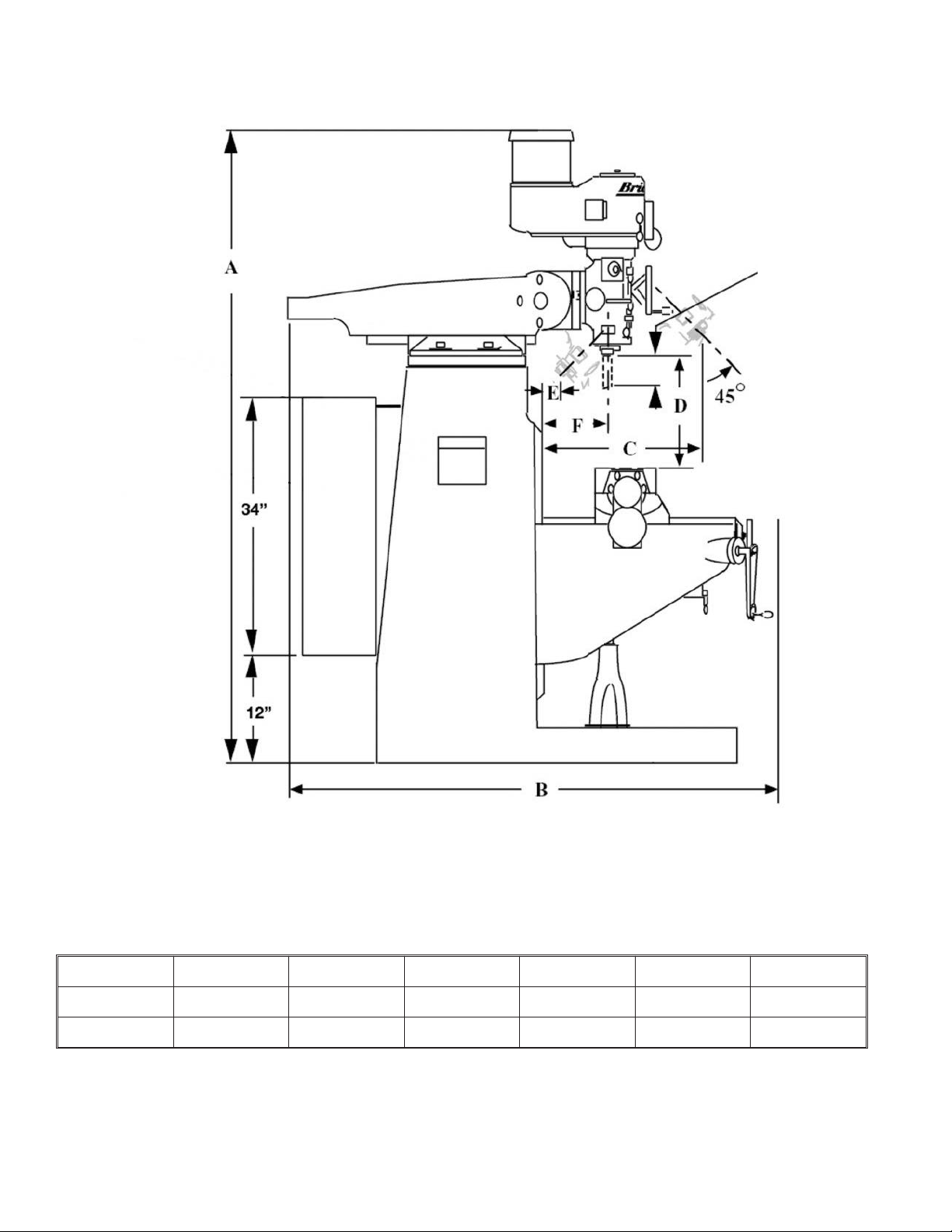
PRINCIPAL DIMENSIONS
TABLE TRAVEL 30.0 in. 762 mm
TABLE LENGTH 48 in. 1219 mm
DimensionABCDEF
Minimum 82 [2083] 51 [1295] 8.75 [222] 2.5 [64)] 0 6.75 [171]
Maximum 84 [2140] 63 [1600] 20.75 [527] 18.25 [470] 12 [305] 18.75 [476]
All dimensions shown in inches [millimeters].
1-4 M-477A
Figure 1.2 - Principal Dimensions
TP5660A
5Inch
Quill Travel

MACHINE DIMENSIONS
FRONT VIEW
M-477A 1-5
Figure 1.3 - Machine Dimensions
(Front View)
46½" (Back Splash)
TP5662A
48" (Optional Coolant Tank)
97" (Table at -X Travel Limit)
67"

SIDE VIEW
1-6 M-477A
Figure 1.4 - Machine Dimensions
(Side View)
TP5661A
84" with
Power
Draw Bar
82" without
Power
Draw Bar
47.4" Maximum
31.4" Minimum
13.0" Maximum
1.0" Minimum

HEAD SPECIFICATIONS
Power 2.0 HP
Motor RPM 1800 RPM
Speed Ranges - RPM Stepless
LOW 60 - 500
HIGH 500 - 4200
Quill Travel 5.0 in. 127 mm
Quill Diameter 3.375 in. 86 mm
Spindle Tapers R-8
#30 Q.C.
Spindle Diameter 1.875 in. 48 mm
Spindle Feed Rate 0.0015/Rev 0.038 mm
0.003/Rev 0.076 mm
0.006/Rev 0.152 mm
Drilling Capacity - Manual 0.87 in. 22 mm dia.
Drilling Capacity - Power 0.37 in. 9.4 mm dia.
Boring Capacity 6.75 in. 152.4 mm dia.
Milling Capacity 2.0 cu. In./min. 32 cc/min.
Spindle to Column - Minimum 6.75 in. 171 mm
Maximum 18.75 in. 476 mm
RECOMMENDATIONS:
1. Use 2, 3, or 4 flute end mills. Eight flute end mills are usually not satisfactory for general milling.
When using shell mills, face mills, or any other tooling, proper machining practice should be
observed.
2. Power Feed can be used for drills up to 0.375 in. diameter. Use manual feed for drills larger
than 0.375 in.
M-477A 1-7

HEAD DIMENSIONS
1-8 M-477A
Figure 1.5 - Head Dimensions
TP5663

SPINDLE SPECIFICATIONS
Spindle Taper R8
Spindle speeds - RPM 60-4200
Motor *2 HP 1.5 kw
Quill travel 5 in 127 mm
Power feed of Quill 0.0015 in. 0.04 mm
per rev of Spindle (3 rates) 0.003 in. 0.08 mm
0.006 in. 0.15 mm
Collet capacity 1/8 - ¾ in x 1/16 in. 3-9 mm x 1.5 mm
Weight 196 lb. 89 kg
*2 HP Continuous - 3 HP Intermittent
M-477A 1-9

- NOTES -
1-10 M-477A
Table of contents
Other Hardinge Power Tools manuals


