Hardmeier ADP-3 User manual

$'3
3URGXFW0DQXDO
5656WR(WKHUQHW$GDSWHU

2
Copyright
OÜ Hardmeier 2002. All rights reserved.
Disclaimer
OÜ Hardmeier reserve the right to change device’s technical
specifications without prior notice.
Manufacturer:
OÜ Hardmeier
Luha 16, 10129 Tallinn
Estonia
Tel: +372 646 01 72
Fax: +372 646 02 90
web: www.hardmeier.ee

3
Contents
Contents 3
Technical Brief 4
Hardware Description 6
Software Description 8
ADP-3 Board Layout 10
Glossary of Terms 11

4
Technical Brief
This document
provides
specific
technical
information
about the ADP-3
Ethernet
Adapter,
including pinout
diagrams,
application
drawings and
configuration
program
description.
The ADP-3 Ethernet Adapter is a device server that provides
simple, reliable and cost-effective network connections for
serial devices using RS232 or RS485 data transfer protocol.
Features:
•10Base-T and RS232/RS485 interfaces on board
•Network protocol: UDP (ICMP partially for testing
purposes)
•Data rate: 9600 bps,1,n
•Data buffering:
oEthernet – 6400 bytes
oRS232/RS485 – 1536 bytes
•Power: DC external power supply 8..14 V
•Current consumption 130 mA (typical), 150 mA (max)
•Dimensions: 80x105x30mm (circuit board), 140x110x35mm
(enclosure)
Package:
ADP-3 package includes the following:
•ADP-3 Ethernet Adapter
•CAT5 Ethernet interface cable
•RS232 cable for configuring the adapter
•RS485 cable for connecting devices with the adapter
•CD-ROM or 3.5” Floppy containing configuration program
and technical documentation
•DC power cord

5
Requirements:
Requirements for configuring the ADP-3 Ethernet Adapter:
•IBM compatible computer, 486 at least
•One free serial port
•3 MB of hard disc space
•No mouse required for using the configuration program

6
Hardware Description
ADP-3 Ethernet
adapter is
powered from
external DC
power supply
8..14 V. Current
consumption is
no more than 150
mA. Power supply
can be connected
through standard
2.1 mm male
chassis
connector or
additional 2-
pole terminal
block. Power
supply
connection is
bipolar type (no
polarity check required).
ADP-3 Ethernet Adapter has 10Base-T Ethernet connector (RJ45
type), 9-pin SUB-D type RS232/RS485 connector, additional 2-
pole terminal block for connecting RS485, 2-pole terminal
block for accessing I2C-compatible EEPROM (terminal block not
mounted), 6-pin pinheader for programming the adapter and
additionally 7 outputs (terminal block not mounted, reserved
for the future).
For indicating the state of adapter there are 4 LED-s in front
panel. From left to right:
1) Red LED. When blinking shortly with long breaks, indi-
cates normal functioning. When burning, shows that
adapter is in programming mode
2) Yellow LED. Indicates that one or more Ethernet packets
transmitted from the adapter to the network may have
collided with another packets. In this case, the adapter
will automatically resend the packets.
3) Green LED 1. Ethernet: receive data. Indicates that the
adapter is receiving Ethernet packets from the network.
4) Green LED 2. Ethernet: transmit data. Indicates that the
adapter is sending packets.

7
There is an 8-pole onboard DIL switch for changing various
settings of the adapter. Functions of the switches:
1) ON – RS485 (-) connected to RS232/RS485 SUB-D connector
OFF – RS485 (-) not connected to RS232/RS485 SUB-D
connector
2) ON – RS485 (+) connected to RS232/RS485 SUB-D connector
OFF – RS485 (+) not connected to RS232/RS485 SUB-D
connector
3) ON – 120 Ohm terminator resistor connected to RS485 line
OFF – resistor disconnected
4) Same as previous (NB! Both switches have to be ON to
enable the resistor!)
5) Not used
6) ON – data coming from RS232/RS485 bus will be transferred
for 5 minutes after last data flow has been received from
Ethernet. After 5 minutes, RS232/RS485 data transfer will
stop
OFF – data coming from RS232/RS485 bus will be
transferred continuously
7) ON – RS485 synchronisation switched on, multiple nodes
get access to adapter one by one
OFF – RS485 synchronisation switched off, the “fastest”
node gets access first
8) ON – RS485 enabled
OFF – RS232 enabled
Cabling
RS232: maximum calble length 15 m
RS485: maximum calble length 1000 m, 24 AWG solid copper
unshielded or shielded twisted pair. 2 terminating resistors
(120 Ohm) are placed across data lines in both ends of the
network (NB! The adapter has built-in switchable terminating
resistor). Daisy-chained network topology preferable.
Ethernet: maximum cable length 100 m, twisted pair (CAT5)

8
Software Description
Software needed for configuring ADP-3 Ethernet Adapter is
provided on the CD-ROM or 3.5” diskette coming with adapter.
Run “adp3cnf.exe” and follow instructions.
After installation run the program. The following window will
open:
ADP-3 Board
IP – enter the IP address of ADP-3 Adapter.
Key – enter the encryption and password key (8 digits 0..255).
Used to protect data being moved accross the network. On first
run the program shows default key saved to adapter during
production. If needed, that key can be freely changed, but
must match application program keys.
StopChar – set character that indicates the end of RS232/RS485
data packet.
Gateway
IP – enter the IP address of the gateway (if available)
Use gateway – if checked, will enable data communication
through gateway. If not checked, no gateway will be used.
PC
IP – enter the IP address of the computer that will control
the work of the adapter
Fixed IP – if checked, the adapter will answer only to
computer whose IP has been entered (“PC IP”). If not checked,
the adapter will answer to all computers.

9
Menus
COM Port – select COM Port that is used to configure the
adapter
About – contact information
Buttons
NB! To use these buttons, the adapter must be in programming
mode. Adapter is set to programming mode by pressing the
button located at the bottom of the adapter enclosure. A round
stick (pencil) can be used for pressing the button.
Save settings – after entering all data needed for
configuring, save the settings to the adapter
Read settings – read previously saved settings from the
adapter
Initialize – after saving the settings, bring the adapter out
of programming mode
The adapter uses UDP protocol. Ethernet data can be sent to
adapter from ports 1025-5000. RS232/RS485 data will be sent
back to the port that was used for sending the request.
NB! you can test the status of the adapter without any
software installed. Click Windows “Start” button, open “Run”
and type in “ping xxx.xxx.xxx.xxx” (replace xxx-s with the IP
address of the adapter). If the adapter is connected and
working, “reply from...” should be displayed several times.

10
ADP-3 Board Layout
1. 2-pole terminal block for DC power supply. No
polarisation.
2. Standard 2.1 mm male chassis connector for DC power
supply. No polarisation.
3. RJ-45 type Ethernet connector.
4. SUB-D 9-pin RS232/RS485 connector.
5. 8-pole DIL switch for changing settings.
6. 6-pin pinheader for programming purposes.
7. 2+2-pole terminal block for connecting RS485 and for
accessing EEPROM (only RS485 terminal block mounted)
8. 8-pole terminal block for 7 additional outputs (not
mounted).
9. LED 1
10. LED 2,3,4
* All terminal blocks have on-board marking
ADP-3 SUB-D connector pinouts
RS232
RS485
1
-
(+)
2
Tx
-
3
Rx
-
4
-
-
5
GND
-
6
-
(-)
7
Tx2
-
8
Rx2
-
9
-
-

11
Glossary of Terms
10Base-T - a 10 Mbps Ethernet standard that uses twisted wire
pairs
Bus – a common pathway (cable) between multiple devices
Gateway – a node (computer) on a network that serves as an
entrance to another network
ICMP - a TCP/IP protocol used to send error and control
messages
IP Address – an identifier for a computer or device on a
network
LED – Light Emitting Diode
Node – network junction or connection point. For example, a
controller connected to RS485 bus
UDP - a protocol within the TCP/IP protocol suite that is used
in place of TCP when a reliable delivery is not required. If
reliable delivery is needed, packet sequence checking and
error notification can be written into the applications
Table of contents
Popular Adapter manuals by other brands
Elements
Elements TwistPort TP-ADAPTORR5AC-PTP-V2 user guide
WiebeTech
WiebeTech RP-PCIE-SCSI user manual
oticon
oticon ConnectLine TV 2.0 Instructions for use
ZyXEL Communications
ZyXEL Communications Powerline Ethernet Multiplug Center PLA491 Specifications
COQON
COQON USBLTE01 manual
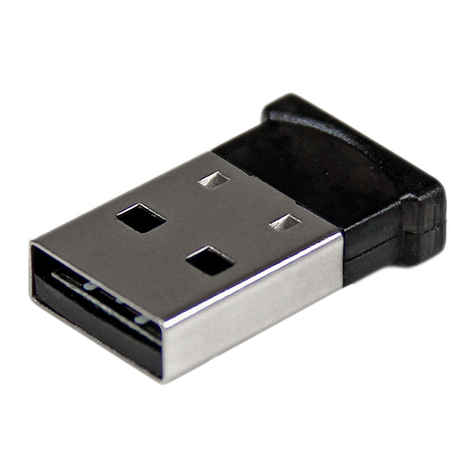
StarTech.com
StarTech.com USBBT1EDR4 Spec sheet
