Wilder Technologies QSFP-DD User manual

QSFP-DD Test Adapter User Manual
Page | 1
©2019 Wilder Technologies, LLC
DocumentNo. 910 -0057-000Rev. A
QSFP-DD
Test Adapter
User Manual

QSFP-DD Test Adapter User Manual
Page | 2
©2019 Wilder Technologies, LLC
DocumentNo. 910 -0057-000Rev. A
Table of Contents
Introduction...........................................................................................................................3
Product Inspection..................................................................................................................5
The QSFP-DD Test Adapter Care and Handling Precautions .......................................................6
General Test Adapter, Cable, and Connector............................................................................8
Handling and Storage..........................................................................................................8
Visual Inspection.................................................................................................................8
Cleaning.............................................................................................................................8
Making Connections ...........................................................................................................8
Electrostatic Discharge Information.........................................................................................9
User Model..........................................................................................................................10
Calibration Through De-Embedding.......................................................................................13
Mechanical and Environmental Specifications........................................................................14
Electrical Specifications.........................................................................................................29
QSFP-DD Mated HCBs/MCB Performance Plots......................................................................30
QSFP-DD MCB (Receptacle) Test Adapter Reference Information ............................................60
Wilder Technologies, LLC – Limited Warranty.........................................................................61
Wilder Technologies, LLC – Terms & Conditions of Sale...........................................................62
Compliance with Environmental Legislation ...........................................................................63
WEEE Compliance Statement ............................................................................................63
Compliance To RoHS 2 Substance Restrictions....................................................................63
Glossary of Terms.................................................................................................................64
Index ...................................................................................................................................65

QSFP-DD Test Adapter User Manual
Page | 3
©2019 Wilder Technologies, LLC
DocumentNo. 910 -0057-000Rev. A
Introduction
This user’s guide documents the QSFP-DD Legacy Plug, QSFP-DD Plug, QSFP-DD RX Plug,
QSFP-DD TX Plug and QSFP-DD Receptacle Test Adapters.
Model Numbers (QSFPDD-TPAK-HCB-LGCY-P, QSFPDD-TPAK-HCB-DD-P, QSFPDD-TPAK-HCB-RX-P,
QSFPDD-TPAK-HCB-TX-P and QSFPDD-TPAHK-MCB-R). The two test adapter types, shown in
Figures 1 and 2, test QSFP-DD interface cables, hosts, and modules to the requirements of the
QSFP-DD MSA and IEEE 802.3cd Standards.
The QSFP-DD HCB (Plug) and QSFP-DD MCB (Receptacle) test adapter assemblies allow easy
access, via 2.92mm (K-Style) connections, to measure or inject data signals.
NOTE: To avoid damaging the cables, use the handling techniques
described in the Care and Handling section before making any
connections or configuring a test setup.
Always use a static-safe workstation when performing tests, as
explained in the “Electrostatic Discharge Information” section.
Figure 1. The QSFP-DD HCB (Plug) Test Adapter (Note: The coaxial cables are configuration dependent
and may be terminated with different connectors and have different color-coding than what is shown.)
QSFP-DD Plug
Connector
Assembly
16 (K-Style) 2.92mm
Connectors (Female
Shown) forHigh-
Speed Testing
Low-Speed
Connector, P2

QSFP-DD Test Adapter User Manual
Page | 4
©2019 Wilder Technologies, LLC
DocumentNo. 910 -0057-000Rev. A
Figure 2. The QSFP-DD MCB (Receptacle)Test Adapter (Note: The coaxial cables areconfiguration
dependent and may be terminated with different connectors than what is shown.)
NOTE: The metal shell of both the plug (QSFP-DD HCB) and
receptacle (QSFP-DD MCB) connectors tie high-speed ground to
chassis ground.
The low-speed 12-position receptacle and plug connectors are keyed and latching (Molex
part number 43645-1200 for the plug TPA and 43650-1204 for the receptacle TPA). The mating
connector housings and contact pins for 26-30awg wire are Molex part number 43640-1201 for
the 12-position housing and 43031-0011 for the plug contacts used with the plug TPA, and
Molex part number 43645-1200 for the 12-position housing and 43030-0011 for the receptacle
contacts used with the receptacle TPA. Replacement parts can be purchased through Molex
distributors.
NOTE: The receiver 2.92mm (K-Style) connections for QSFP-DD are
normally AC coupled. The QSFP-DD plug and receptacle TPAs do NOT
have internal DC Blocks. This allows for parametric testing through
the TPAs. Normal testing may require DC Blocks (May be optionally
ordered from Wilder Technologies). Refer to the Electrical
Specifications section of this document for DC Block performance
parameters.
32 (K-Style)
2.92mm
Connectors
(Female Shown)
for High-Speed
Low-Speed Connector
(Side, Not Shown)
QSFP-DD
Receptacle

QSFP-DD Test Adapter User Manual
Page | 5
©2019 Wilder Technologies, LLC
DocumentNo. 910 -0057-000Rev. A
Product Inspection
Upon receiving QSFP-DD Test Adapters from Wilder Technologies, perform the following
product inspection:
•Inspect the outer shipping container, foam-lined instrument case, and product for damage.
Retain the outer cardboard shipping container until the contents of the shipment have been
inspected for completeness and the product has been checked mechanically and electrically. Use
the foam-lined instrument-case for secure storage of the Wilder Technologies QSFP-DD Test
Adapter when not in use.
•Locate the shipping list and verify that all items ordered were received.
•In the unlikely event that the product is defective or incomplete, the “Limited Warranty” section
discusses how to contact Wilder Technologies for technical assistance and/or how to package the
product for return.

QSFP-DD Test Adapter User Manual
Page | 6
©2019 Wilder Technologies, LLC
DocumentNo. 910 -0057-000Rev. A
The QSFP-DD Test Adapter Care and Handling Precautions
The QSFP-DD Test Adapters requires careful handling to avoid damage. Improper handling
techniques, or using too small a cable bend radius, can damage the coaxial cable connections
within the adapter housing or the cables themselves. This can occur at any point along the
cable. To achieve optimum performance and to prolong the QSFP-DD TPA’s life, observe the
following handling precautions:
•CAUTION 1: Avoid Torque Forces (Twisting)
While individual coaxial cables within the test adapter have some rotational freedom,
twisting the QSFP-DD TPA as a unit, with one end held stationary, may damage or severely
degrade performance. Adherence to Caution 5 (below) helps to avoid twisting.
•CAUTION 2: Avoid Sharp Cable Bends
Never bend coaxial cables into a radius of 26 mm (1-inch) or less. Never bend cables
greater than 90°. Single or multiple cable bends must be kept within this limit. Bending the
QSFP-DD TPA cables less than a 26mm (1-Inch) radius will permanently damage or severely
degrade test adapter performance.
•CAUTION 3: Avoid Cable Tension (Pull Forces)
Never apply tension (pull forces) to an individual coaxial cable that is greater than 2.3 kg
(5 lbs.). To avoid applying tension, always place accessories and equipment on a surface
that allows adjustment to eliminate tension on the QSFP-DD TPA and cables. Use adjustable
elevation stands or apparatus to accurately place and support the QSFP-DD TPA.
•CAUTION 4: Connect the QSFP-DD Test Adapter First
To prevent twisting, bending, or applying tension to the coaxial cables when connecting a
QSFP-DD TPA, always attach the QSFP-DD TPA to the device under test (DUT) or cable under
test before attaching any 2.92mm (K-Style) connectors. Carefully align the QSFP-DD
connectors and then gently push the connectors together until fully seated.
If the QSFP-DD TPA must be turned or twisted to make connection to the DUT, avoid using
the QSFP-DD TPA housing alone to make this occur.Try to distribute the torque forces along
the length of the test setup and cabling. If this is not possible, it is recommended to first
loosen or disconnect the 2.92mm (K-Style) connections at the QSFP-DD TPA, make the
connection to the DUT and then re-tighten or attach the test equipment leads.
NOTE: Only grip the test adapter housing when inserting or
extracting the QSFP-DD TPA to or from the DUT. Pulling directly on
the QSFP-DD TPA cables or using them to insert the QSFP-DD TPA
may cause damage.
•CAUTION 5: Carefully Make High-Speed (2.92mm, K-Style) Connections
To connect the QSFP-DD TPA 2.92mm (K-Style) connectors, follow these steps:
1. Hold the cable stationary by grasping the cable at the black heat-shrink section
near the High-Speed connector.
2. Insert the mating High-Speed connector barrel and hand-tighten the free-spinning
2.92mm connector (K-Style) nut onto the connector while avoiding pulling,
bending, or twisting the QSFP-DD TPA coaxial cable.

QSFP-DD Test Adapter User Manual
Page | 7
©2019 Wilder Technologies, LLC
DocumentNo. 910 -0057-000Rev. A
3. The QSFP-DD TPA 2.92mm connectors (K-Style) have flats that accept an open-end
1/4-inch or 5/16-inch wrench, depending on configuration. When attaching
instrument cables to the QSFP-DD TPA, it is recommended that the QSFP-DD TPA
high-speed connectors be mechanically held and the test leads be tightened to the
equipment manufacturer’s torque recommendations, normally 5 in-lbs., using an
open-end torque wrench.
If the test set-up requires repositioning, first loosen or disconnect the 2.92mm (K-Style)
connections to avoid twisting, bending, or tension.
NOTE: A drop in signal amplitude by half or 6dB during the testing of
a channel may indicate that a cable has been mechanically pulled
free of coaxial cable connections internal to the assembly. This could
be determined by checking if the cable has any lateral play relative
to the TPA. This would only occur when the TPA has exceeded the
pull force as specified within the mechanical specification. If the
cable cannot be re-seated, the test adapter will need to be sent back
to the factory for service.
•CAUTION 6: Independently Support Instrument Cables or Accessories
Excessive weight from instrument cables and/or accessories connected to the QSFP-DD TPA
can cause damage or affect the test adapter performance. Be sure to provide appropriate
means to support and stabilize all test set-up components.
•CAUTION 7: ESD Sensitivity
The QSFP-DD test adapters are passive components and are not in themselves sensitive to
electrostatic discharge. However, when an active DUT is installed, that device becomes
susceptible to ESD. Observe proper ESD precautions, further discussed later in this
document.

QSFP-DD Test Adapter User Manual
Page | 8
©2019 Wilder Technologies, LLC
DocumentNo. 910 -0057-000Rev. A
General Test Adapter, Cable, and Connector
Observing simple precautions can ensure accurate and reliable measurements.
Handling and Storage
Before each use of the QSFP-DD TPA, ensure that all connectors are clean. Handle all cables
carefully and store the QSFP-DD TPA in the foam-lined instrument case when not in use, if
possible. Do not set connectors contact end down. Install the high-speed connector protective
end caps when the QSFP-DD TPA is not in use.
Visual Inspection
Be sure to inspect all cables carefully before making a connection. Inspect all cables for
metal particles, scratches, deformed threads, dents, or bent, broken, or misaligned center
conductors. Do not use damaged cables.
Cleaning
If necessary, clean the connectors using low-pressure (less than 60 PSI) compressed air or
nitrogen with an effective oil-vapor filter and condensation trap. Clean the cable threads, if
necessary, using a lint-free swab or cleaning cloth moistened with isopropyl alcohol. Always
completely dry a connector before use. Do not use abrasives to clean the connectors.Re-
inspect connectors, making sure no particles or residue remains.
Making Connections
Before making any connections, review the “Care and Handling Precautions”section. Follow
these guidelines when making connections:
•Align cables carefully
•Make preliminary connection lightly
•To tighten, turn connector nut only
•Do not apply bending force to cable
•Do not over-tighten preliminary connections
•Do not twist or screw-in cables
•Use an appropriately sized torque wrench, and do not tighten past the “break” point of the
torque wrench (normally 5 inch pounds)

QSFP-DD Test Adapter User Manual
Page | 9
©2019 Wilder Technologies, LLC
DocumentNo. 910 -0057-000Rev. A
Electrostatic Discharge Information
Protection against electrostatic discharge (ESD) is essential while connecting, inspecting, or
cleaning the QSFP-DD TPA test adapter and connectors attached to a static-sensitive circuit
(such as those found in test sets).
Electrostatic discharge can damage or destroy electronic components. Be sure to perform all
work on electronic assemblies at a static-safe work station, using two types of ESD protection:
•Conductive table-mat and wrist-strap combination
•Conductive floor-mat and heel-strap combination
When used together, both types provide a significant level of ESD protection. Used alone, the
table-mat and wrist-strap combination provide adequate ESD protection. To ensure user safety,
the static-safe accessories must provide at least 1 MΩ of isolation from ground. Acceptable ESD
accessories may be purchased from a local supplier.
WARNING: These techniques for a static-safe work station should
not be used when working on circuitry with a voltage potential
greater than 500 volts.
QSFP-DD Test Adapter User Manual
Page | 10
©2019 Wilder Technologies, LLC
DocumentNo. 910 -0057-000Rev. A
User Model
The QSFP-DD TPAs are capable of performing to the requirements of both IEEE and SFF
specifications, limited only by the specifications, environmental, care and handling of this
document.
In the case where the laboratory source or load is not used in the test, it must be replaced
with RF terminations on each unused signal. (NOTE: DC Blocks and RF terminators are
optionally offered by Wilder Technologies.)
The following examples are suggestions for possible testing setups.
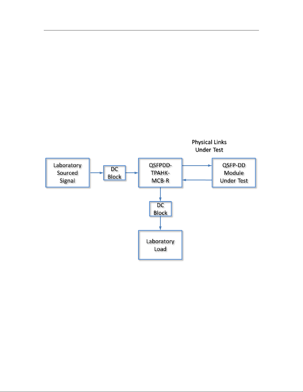
In this first example, a QSFPDD TPAHK-MCB-R is used to test a QSFP-DD Module:
QSFP-DD Test Adapter User Manual
Page | 11
©2019 Wilder Technologies, LLC
DocumentNo. 910 -0057-000Rev. A
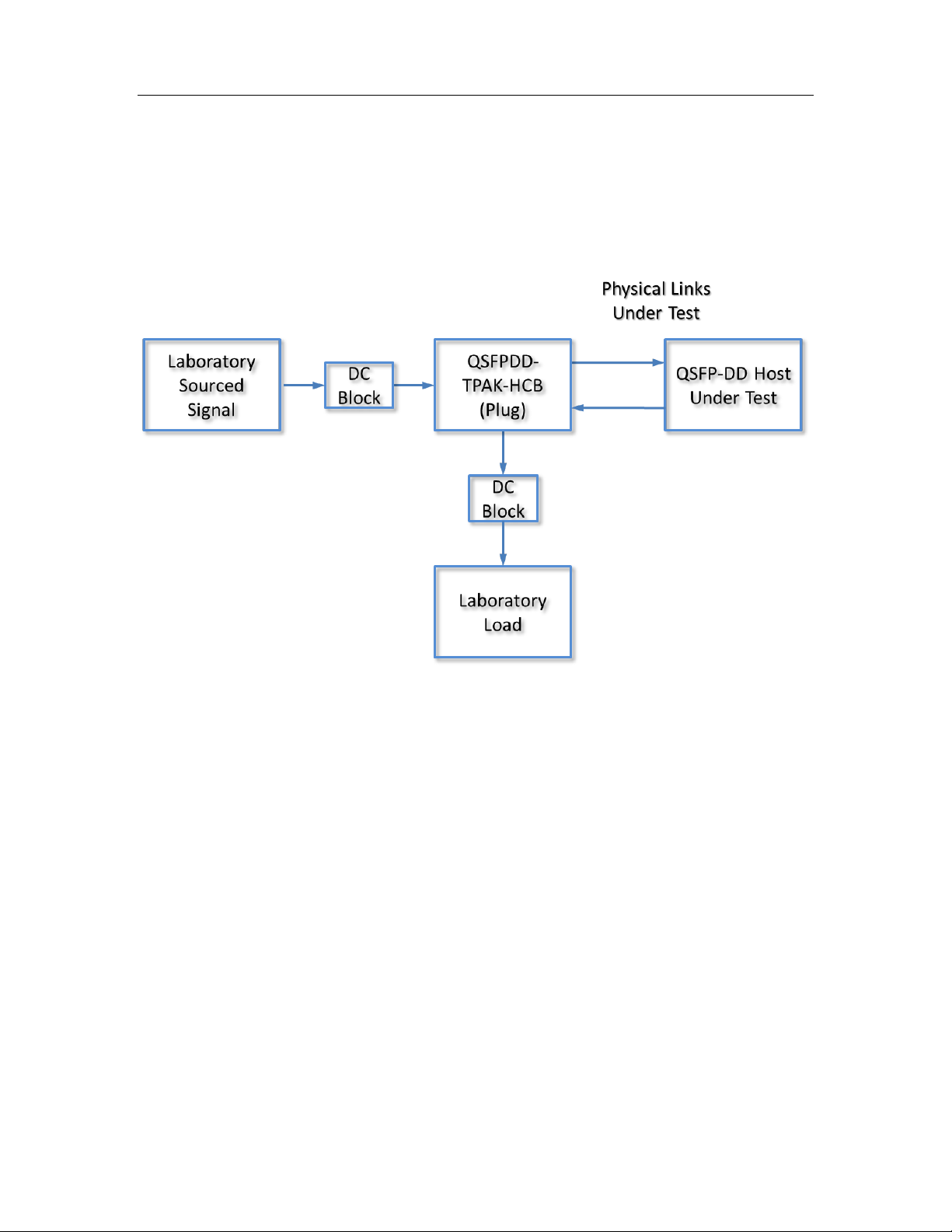
The second example shows a QSFPDD-TPAK-HCB (Plug) is used to test a host:
In the case where the laboratory source or load is not used in the test, it must be replaced
with RF terminations on each unused signal. (NOTE: DC Blocks and RF terminators are
optionally offered by Wilder Technologies.)
QSFP-DD Test Adapter User Manual
Page | 12
©2019 Wilder Technologies, LLC
DocumentNo. 910 -0057-000Rev. A
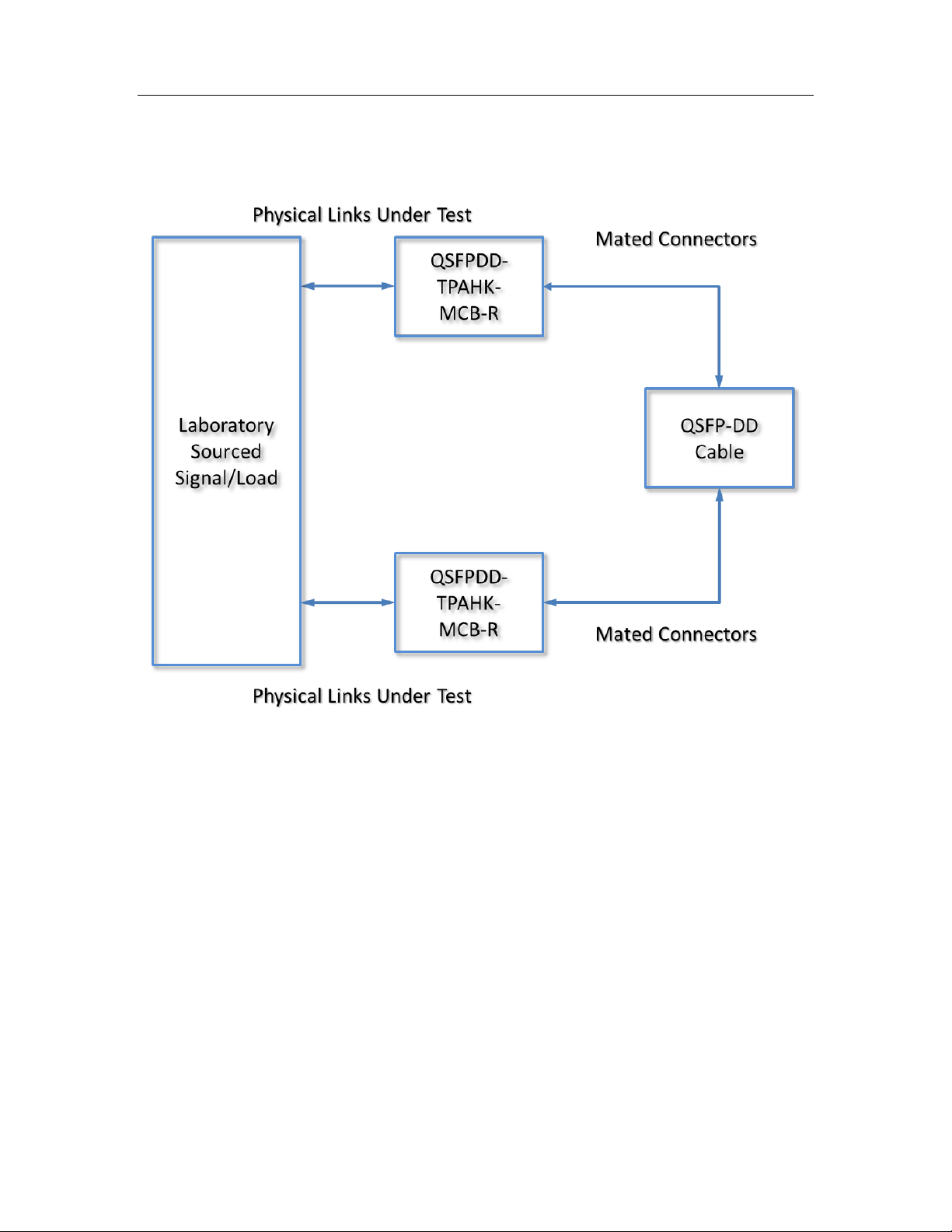
The third example shows two QSFPDD-TPAHK-MCB-R’s used for testing a QSFP-DD cable:

QSFP-DD Test Adapter User Manual
Page | 13
©2019 Wilder Technologies, LLC
DocumentNo. 910 -0057-000Rev. A
Calibration Through De-Embedding
The QSFP-DD Test Adapters are fully passive components. Therefore, calibration
compensating for the losses must occur within the test instrumentation that drives the QSFP-
DD Receivers or looks at the response of the QSFP-DD Transmitters.
The QSFP-DD TPA’s have Touchstone S4P files for de-embedding the electrical length and
losses within the TPA up to the QSFP-DD connector interface pads. (Contact Wilder
Technologies, support@wilder-tech.com,to obtain a copy of the S4P files.) The Touchstone S4P
files enable the test engineer to compensate for the last four of the following six repeatable,
systematic errors that occur when moving the reference plane:
•Signal leakage effects: Directivity errors
•Signal leakage effects: Crosstalk errors
•Reflection effects: Source Impedance Mismatching errors
•Reflection effects: Load Impedance Mismatching errors
•Bandwidth effects: Receiver Transmission in Test Equipment errors
•Bandwidth effects: Receiver Reflection-tracking in Test Equipment errors
These errorsare corrected on each port. Refer to the Instrument Manual for instructions on
the instrument’s specific de-embedding process.
NOTE: The reference plane is the boundary, both physically and
electrically, between the calibrated and uncalibrated portions of
the circuit. Everything outside the reference plane is considered
part of the DUT. Any instrument that does not use calibration or de-
embedding of the test fixture defines the DUT as the total of
externally connected components. If the de-embedding file is not
used, all of the QSFP-DD TPA and associated coaxial cables, as well as
cables connecting the TPA assembly to the test instrument, would be
a part of the DUT.
Non-repeatable errors, such as drift or random errors, can be reduced but not corrected.
Drift errorsaggregate over time or with environmental changes such as temperature shift. To
eliminate drift errors,perform an instrumentation-level calibration.
A random error cannot be corrected through calibration since the error occurred randomly.
Random errors are typically associated with either test instrument noise or test repeatability
problems. Reduce test instrument noise by increasing source power, lowering the IF
bandwidth, or averaging results over multiple sweeps. Reduce test repeatability problems
through the use of a torque wrench or, again, by averaging over multiple sweeps.

QSFP-DD Test Adapter User Manual
Page | 14
©2019 Wilder Technologies, LLC
DocumentNo. 910 -0057-000Rev. A
Mechanical and Environmental Specifications
NOTE: All specifications in this manual are subject to change.
Table 1. General Specifications
ITEM DESCRIPTION
Usage Environment Controlled indoor environment
Plug Test Adapter Length (w/standard cables)
263.00 mm +/- 2 mm (10.35 inches +/- .08 inches)
(Characteristic)
Receptacle Test Adapter Length (w/standard
cables, end to end)
236.22 mm +/- 2 mm (9.30 inches +/- .08 inches)
(Characteristic)
Receptacle Test Adapter Housing Dimensions 125.98 x 106.43 x 74.68 (4.96 x 4.19 x 2.94 inches) (L, W, H)
Operating Temperature 0°C to +55°C (32°F to +131°F) (Characteristic)
Storage Temperature -40°C to +70°C (-40°F to +158°F) (Characteristic)
QSFPDD-TPAK-HCB (Plug)
Each of the four configurations of Plug-Type QSFPDD-TPAK-HCB test adapters (Legacy, DD, Rx
and Tx) provide sixteen 2.92mm (K-Style) connectors (four lanes of primary differential signals).
Labels clearly mark each cable or connector. The following figure refers to the pin-description
tables for the QSFPDD-TPAK-HCB (Plug) test adapters.
Figure 3. Cable Connectors (QSFPDD-TPAK-HCB shown). (Note: The coaxial cables areconfiguration
dependent and may be terminated with different connectors and have different color-coding than what
is shown.)
Low-Speed Connector, P2
(See Table 2)
QSFP-DD Plug Connector
(See Table 3 forLegacy)
(See Table 4 for DD)
(See Table 5 forRx)
(See Table 6 forTx)
16 (K-Style) 2.92mm
Connectors (Female
Shown) forHigh-
Speed Testing
Color-Coded and Imprinted Markings
(Large Colored = ChannelNumber)
(Short White = Transmit Side)
(Short Red = Positive Polarity)
See Tables 3 (Legacy), 4 (DD), 5 (Rx), 6 (Tx)
QSFP-DD Test Adapter User Manual
Page | 15
©2019 Wilder Technologies, LLC
DocumentNo. 910 -0057-000Rev. A
Table 2. QSFPDD-TPAK-HCB (Plug) 12-Position Cable Connector(Low-Speed).
(NOTE: Connections are common to Legacy, DD, Rx and Tx configurations)
LABEL PIN NO. COLOR ID FOR HCB DESCRIPTION
GND Pin 1 Black Signal (RF Ground) and Supply (Power) Common
MPL Pin 2 Black Module Present
ITL Pin 3 Black Interrupt
SDA Pin 4 Black SDA, I2C Data for DDC
SCL Pin 5 Black SCL, I2C Clock for DDC
RSL Pin 6 Black Module Reset
MSL Pin 7 Black Module Select
LPM Pin 8 Black Low Power Mode
VCC Pin 9 Not Present/Connected Vcc1 module power supply (+3.3V)
VCR Pin 10 Not Present/Connected VccR, module receiver power supply (+3.3V)
VCT Pin 11 Not Present/Connected VccT, module transmitter power supply (+3.3V)
GND Pin 12 Black Signal (RF Ground) and Supply (Power) Common

QSFP-DD Test Adapter User Manual
Page | 16
©2019 Wilder Technologies, LLC
DocumentNo. 910 -0057-000Rev. A
Table 3. QSFPDD-TPAK-HCB-LGCY-P (Legacy Plug) Pin Assignments
Pin Description Connector
Pin Number
Destination (HCB) Color ID for Data
Line Polarity
Color Identification
(HCB)
Ground 1
Coax Shield and
P2 Pin 1, 12
N/A Black Insulation
Tx2n 2 Tx2- Black White/Blue
Tx2p 3 Tx2+ Red White/Blue
Ground 4
Coax Shield and
P2 Pin 1, 12
N/A Black Insulation
Tx4n 5 Tx4- Black White/Red
Tx4p 6 Tx4+ Red White/Red
Ground 7
Coax Shield and
P2 Pin 1, 12
N/A Black Insulation
MSL 8 P2 Pin 7 N/A Black Insulation
RSL 9 P2 Pin 6 N/A Black Insulation
VccR 10
Not
Present/Connected
N/A
Not
Present/Connected
N/A
SCL 11 P2 Pin 5 N/A Black Insulation
SDA 12 P2 Pin 4 N/A Black Insulation
Ground 13
Coax Shield and
P2 Pin 1, 12
N/A Black Insulation
Rx3p 14 Rx3+ Red Green
Rx3n 15 Rx3- Black Green
Ground 16
Coax Shield and
P2 Pin 1, 12
N/A Black Insulation
Rx1p 17 Rx1+ Red Yellow
Rx1n 18 Rx1- Black Yellow
Ground 19
Coax Shield and
P2 Pin 1, 12
N/A Black Insulation
Ground 20
Coax Shield and
P2 Pin 1, 12
N/A Black Insulation
Rx2n 21 Rx2- Black Blue
Rx2p 22 Rx2+ Red Blue
Ground 23
Coax Shield and
P2 Pin 1, 12
N/A Black Insulation
Rx4n 24 Rx4- Black Red
Rx4p 25 Rx4+ Red Red
Ground 26
Coax Shield and
P2 Pin 1, 12
N/A Black Insulation
MPL 27 P2 Pin 2 N/A Black Insulation

QSFP-DD Test Adapter User Manual
Page | 17
©2019 Wilder Technologies, LLC
DocumentNo. 910 -0057-000Rev. A
ITL 28 P2 Pin 3 N/A Black Insulation
VccT 29
Not
Present/Connected
N/A
Not
Present/Connected
N/A
Vcc1 30
Not
Present/Connected
N/A
Not
Present/Connected
N/A
LPM 31 P2 Pin 8 N/A Black Insulation
Ground 32
Coax Shield and
P2 Pin 1, 12
N/A Black Insulation
Tx3p 33 Tx3+ Red White/Green
Tx3n 34 Tx3- Black White/Green
Ground 35
Coax Shield and
P2 Pin 1, 12
N/A Black Insulation
Tx1p 36 Tx1+ Red White/Yel low
Tx1n 37 Tx1- Black White/Yellow
Ground 38
Coax Shield and
P2 Pin 1, 12
N/A Black Insulation

QSFP-DD Test Adapter User Manual
Page | 18
©2019 Wilder Technologies, LLC
DocumentNo. 910 -0057-000Rev. A
Table 4. QSFPDD-TPAK-HCB-DD-P (DD Plug) Pin Assignments
Pin Description Connector
Pin Number
Destination (HCB) Color ID for Data
Line Polarity
Color Identification
(HCB)
MSL 8 P2 Pin 7 N/A Black Insulation
RSL 9 P2 Pin 6 N/A Black Insulation
VccR 10
Not
Present/Connected
N/A
Not
Present/Connected
N/A
SCL 11 P2 Pin 5 N/A Black Insulation
SDA 12 P2 Pin 4 N/A Black Insulation
MPL 27 P2 Pin 2 N/A Black Insulation
ITL 28 P2 Pin 3 N/A Black Insulation
VccT 29
Not
Present/Connected
N/A
Not
Present/Connected
N/A
Vcc1 30
Not
Present/Connected
N/A
Not
Present/Connected
N/A
LPM 31 P2 Pin 8 N/A Black Insulation
Ground 39
Coax Shield and
P2 Pin 1, 12
N/A Black Insulation
Tx6n 40 Tx6- Black White/Br own
Tx6p 41 Tx6+ Red White/Brown
Ground 42
Coax Shield and
P2 Pin 1, 12
N/A Black Insulation
Tx8n 43 Tx8- Black White/White
Tx8p 44 Tx8+ Red White/White
Ground 45
Coax Shield and
P2 Pin 1, 12
N/A Black Insulation
Reserved 46
Not
Present/Connected
N/A
Not
Present/Connected
N/A
VS1 47
Not
Present/Connected
N/A
Not
Present/Connected
N/A
VccRx1 48
Not
Present/Connected
N/A
Not
Present/Connected
N/A
VS2 49
Not
Present/Connected
N/A
Not
Present/Connected
N/A
VS3 50
Not
Present/Connected
N/A
Not
Present/Connected
N/A
Ground 51
Coax Shield and
P2 Pin 1, 12
N/A Black Insulation
Rx7p 52 Rx7+ Red Violet
Rx7n 53 Rx7- Black Violet
Ground 54
Coax Shield and
P2 Pin 1, 12
N/A Black Insulation

QSFP-DD Test Adapter User Manual
Page | 19
©2019 Wilder Technologies, LLC
DocumentNo. 910 -0057-000Rev. A
Rx5p 55 Rx5+ Red Orange
Rx5n 56 Rx5- Black Orange
Ground 57
Coax Shield and
P2 Pin 1, 12
N/A Black Insulation
Ground 58
Coax Shield and
P2 Pin 1, 12
N/A Black Insulation
Rx6n 59 Rx6- Black Brown
Rx6p 60 Rx6+ Red Brown
Ground 61
Coax Shield and
P2 Pin 1, 12
N/A Black Insulation
Rx8n 62 Rx8- Black White
Rx8p 63 Rx8+ Red White
Ground 64
Coax Shield and
P2 Pin 1, 12
N/A Black Insulation
NC 65
Not
Present/Connected
N/A
Not
Present/Connected
N/A
Reserved 66
Not
Present/Connected
N/A
Not
Present/Connected
N/A
VccTx1 67
Not
Present/Connected
N/A
Not
Present/Connected
N/A
Vcc2 68
Not
Present/Connected
N/A
Not
Present/Connected
N/A
ePPS 69
Not
Present/Connected
N/A
Not
Present/Connected
N/A
Ground 70
Coax Shield and
P2 Pin 1, 12
N/A Black Insulation
Tx7p 71 Tx7+ Red White/Violet
Tx7n 72 Tx7- Black White/Vi olet
Ground 73
Coax Shield and
P2 Pin 1, 12
N/A Black Insulation
Tx5p 74 Tx5+ Red White/Orange
Tx5n 75 Tx5- Black White/Orange
Ground 76
Coax Shield and
P2 Pin 1, 12
N/A Black Insulation

QSFP-DD Test Adapter User Manual
Page | 20
©2019 Wilder Technologies, LLC
DocumentNo. 910 -0057-000Rev. A
Table 5. QSFPDD-TPAK-HCB-RX-P (Rx Plug) Pin Assignments
Pin Description Connector
Pin Number
Destination (HCB) Color ID for Data
Line Polarity
Color Identification
(HCB)
MSL 8 P2 Pin 7 N/A Black Insulation
RSL 9 P2 Pin 6 N/A Black Insulation
VccR 10
Not
Present/Connected
N/A
Not
Present/Connected
N/A
SCL 11 P2 Pin 5 N/A Black Insulation
SDA 12 P2 Pin 4 N/A Black Insulation
Ground 13
Coax Shield and
P2 Pin 1, 12
N/A Black Insulation
Rx3p 14 Rx3+ Red Green
Rx3n 15 Rx3- Black Green
Ground 16
Coax Shield and
P2 Pin 1, 12
N/A Black Insulation
Rx1p 17 Rx1+ Red Yellow
Rx1n 18 Rx1- Black Yellow
Ground 19
Coax Shield and
P2 Pin 1, 12
N/A Black Insulation
Ground 20
Coax Shield and
P2 Pin 1, 12
N/A Black Insulation
Rx2n 21 Rx2- Black Blue
Rx2p 22 Rx2+ Red Blue
Ground 23
Coax Shield and
P2 Pin 1, 12
N/A Black Insulation
Rx4n 24 Rx4- Black Red
Rx4p 25 Rx4+ Red Red
Ground 26
Coax Shield and
P2 Pin 1, 12
N/A Black Insulation
MPL 27 P2 Pin 2 N/A Black Insulation
ITL 28 P2 Pin 3 N/A Black Insulation
VccT 29
Not
Present/Connected
N/A
Not
Present/Connected
N/A
Vcc1 30
Not
Present/Connected
N/A
Not
Present/Connected
N/A
LPM 31 P2 Pin 8 N/A Black Insulation
Reserved 46
Not
Present/Connected
N/A
Not
Present/Connected
N/A
VS1 47
Not
Present/Connected
N/A
Not
Present/Connected
N/A
This manual suits for next models
5
Table of contents
Other Wilder Technologies Adapter manuals


