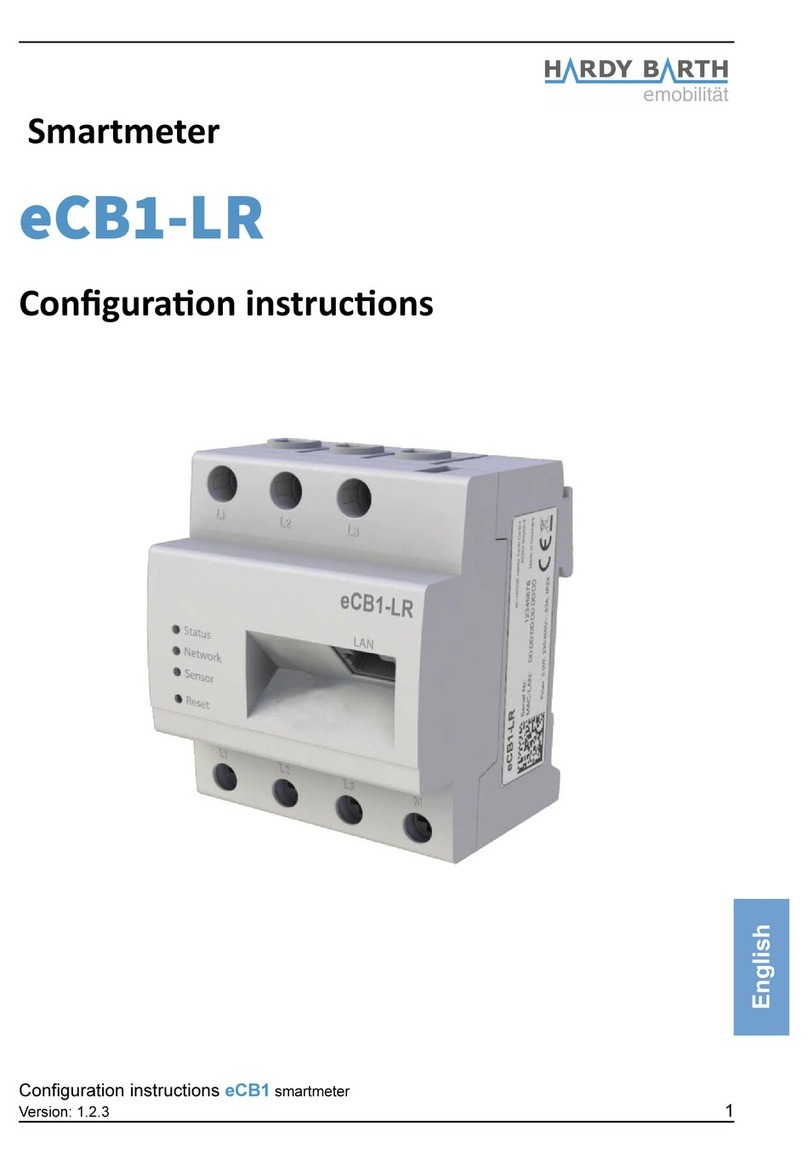
Hardy Barth eCB1-LR Instruction sheet

Smartmeter
eCB1-LR
Configuration manual
Configuration manual eCB1 Smartmeter
Version: 1.2.1 1
English

Contents
Contact data...................................................................................................................2
Note.................................................................................................................................................4
General information about eCB1....................................................................................................4
Meaning of LED status....................................................................................................................4
Reset function..................................................................................................................................4
Setup of direct LAN connection to the eCB1................................................................5
Anklemmen der BUS-Verbindung zwischen Wallbox und eCB1...................................7
Configuration of eCB1 LR MP+ (metering point)...........................................................8
Opening the Webinterface..............................................................................................................8
Language..........................................................................................................................................8
Date and time..................................................................................................................................9
Networksettings.............................................................................................................................1
Internal...........................................................................................................................................11
Charge connector...........................................................................................................................11
Setup finish....................................................................................................................................12
Explanation of Webinterface........................................................................................................13
Configuration of eCB1 LR PV (PV load control)............................................................14
Date and time...............................................................................................................................15
Network settings...........................................................................................................................16
House connection.........................................................................................................................17
Charging point................................................................................................................................19
Setup finish...................................................................................................................................21
Firmware-Update..........................................................................................................................22
Important settings for operation..................................................................................................22
Charge log.....................................................................................................................................25
Configuration manual eCB1 Smartmeter
Version: 1.2.1 3

Note
To prevent confusion between the different models of the eCB1 be sure to check the
model specification on the package.
General information about eCB1
Meaning of LED status
Status-LED
Permanent green The eCB1 is ready.
Slowly flashing in green The device is starting.
Qui kly flashing in green A firmware update is running.
Glowing or flashing in red or An error occurred.
orange
Network-LED
Off no connection
Permanent green connection active
Green flashing Network activity
Bus-LED
Off Device is not configured.
Green connection is okay.
Orange No device detected.
Red BUS error
Reset fun tion
You can reset the ecB1 to network settings or simply restart the device by pressing the
reset button. The time period of pressure applied is important.
Reset to fa tory settings
With a pointy object press the Reset button for 4 to 10 seconds.
Restart the eCB1
To restart use a pointy object to press the Reset-button for 1 second to 3 seconds.
The installation and configuration of the described devices should be executed in the
stated order.
Configuration manual eCB1 Smartmeter
Version: 1.2.1 4

Setup of dire t LAN onne tion to the eCB1
Step 1: Install eCB1 (if included externally) and/or connect it to the power supply.
Step 2: Integrate the eCB1 in your network a PC or a laptop with help of a LAN cable
(see image).
Please Note: Please make sure that only one unfigured eCB1 is connected to your network in order to
avoid name collisions.
1. Start your browser.
2. Type in the following URL „http://e b1.lo al“ (see image below).
1. The user interface of the eCB1 opens.
Configuration manual eCB1 Smartmeter
Version: 1.2.1 5

Should the interface not open please verify the following things:
1. The name resolution does not work.
Please open the interface via the actual IP-adress of the eCB1.
„(http://<IP>/)“
Open the desktop of your router and read the IP address of the eCB1 (see manual of your
router).
If you have Windows XP/7/8: Install Apple Bonjour®. You can find the download link on
www.apple.com. Then try to enter the URL again.
Please note: Apple Bonjour® is also included in Apple iTunes®.
Alternatively contact the network administrator.
2. The Status LED is not glowing.
If the Status LED of the eCB1 does not glow it means that the
Smartmeter is not provided with any power.
Please make sure that at least one of the phase conductors L1 and
the neutral conductor N are connected to the eCB1.
3. The Status-LED glows or blinks in red.
If the Status LED glows or blinks in red an error has occurred.
Please restart the eCB1 by pressing the Reset-button with a pointy
object for about 1-3 se onds.
4. The Network-LED is not glowing
The network cable is not properly/correctly connected to the network port if the
network-LED does not glow. Please make sure that you have inserted both ends of the
cable properly and correctly.
5. eCB1 ould not be found in the network
This means that eCB1 is not located in the same local network. Please connect the
eCB1 with the same Router/Switch as the one of your PC’s/laptop’s.
If that doesn’t solve your problem, please reset the eCB1 to its fa tory settings by
pressing the Reset-button with a pointy obje t for about 4 se onds to 10 se onds.
Configuration manual eCB1 Smartmeter
Version: 1.2.1 6

Conne ting the eCB1 and the Pµ1 via BUS
Image 1: shows the BUS-clamps of the cPµ1.
Image 2: shows the BUS-clamps of the eCB1.
(Please note the green marks in Image 1 )
Image 1
cPµ1 charging
station
Image 2
ecB1 and Bus terminal
These have to be connected as follows:
plug the brown wire (second slot on the eCB1) in
lamp 1 (shown in Image 1).
plug the bla k wire (third slot on the eCB1) in
lamp 2.
Last step you plug the blue wire (first slot on the
eCB1) in lamp 3.
Configuration manual eCB1 Smartmeter
Version: 1.2.1 7

Configuration of eCB1 LR MP (metering point)
Opening the Webinterface
Access the Webinterface of the eCB1 MP+ (metering point at the house connection) by
entering its IP address in your webbrowser.
Prior to that it has to be integrated into the network of the house. Then through the
interface of the router you can find the IP address of all eCB1 including this one.
If therer is no other configured eCB1 in your Network you can contact the eCB1 MP+ with
http://ecb1.local for first configuration.
If the Domane Name System should not work you can find the IP adress through the
Webinterface of your router.
The following page should open up:
Please click “proceed” to get to the following section:
Language
Here you can set:
- language
- the country in which you are installing the charging station
- the time zone
Configuration manual eCB1 Smartmeter
Version: 1.2.1 8

Date and time
Click “proceed” to get to the following screen:
Here you can set the time and date manually or automatically.
Manual setting
Click on the Date button and choose the current date. Then continue with the Time
button to enter the current time.
Please separate the hours minutes and seconds with colons.
To complete the settings press “set time” and the settings will be saved.
Automati setting
In this case “Date” and “Time” do not need any entries.
There are pre-set internet pages in section “NTP Server 1” and “NTP Server 2”. These will
connect you automatically with a time server.
Click on “Set time by ntp” to save your settings. If you want to connect with a different or
your own time server please enter the internet address manually.
By clicking “automati syn hronise at boot” the time will be synchronised automatically
after every outage (power network etc.).
Configuration manual eCB1 Smartmeter
Version: 1.2.1 9

Network settings
After completion of the time and date settings click on “Continue” to get to the next
section.
Choose “DHCP” as protocol.
Your DHCP Server (e.g Router) will do further settings automatically and fill the remaining
blank spaces.
There are no other settings to be made in the section except giving a hostname.
If you choose “static” as protocol please contact your network administrator in order to fill
the remaining forms according to your network.
Select a distinct hostname. Usually the device responds to the given hostname meaning
the URL will change to >givenname<.local instead. Upon delivery the hostname given is
“e b1.lo al”.
Configuration manual eCB1 Smartmeter
Version: 1.2.1 10

Internal
In this section you will determine the function of the eCB1 which in this case is to be the
metering point at the house onne tion.
Therefore choose “building service head” as device funktion as well.
The button “measurement via current transformer” must only be activated when there is a
measuring transformer needed/installed. Press on the button to activate (orange) and
deactivate (grey). Usually (by German law) a measuring transformer is required when the
house connection exceeds 63A.
To prevent confusion between both the eCP1 MP+ and eCP1 PV you can choose a name
for the device.
Charge connector
Since the eCB1 MP+ is solely for metering there is no charging point to define. Choose
“no EVCC”.
Configuration manual eCB1 Smartmeter
Version: 1.2.1 11

Setup finish
After completion of the initial setup the device restarts to implement/save all the settings.
Restarting process can take up to five minutes.
Should no interface appear after five minutes please refresh the page or enter the IP-
address again.
The setup finish ends the configuration process of the eCB1 LR MP+ and you can now go
on with the configuration of a second eCB1.
Configuration manual eCB1 Smartmeter
Version: 1.2.1 12

Explanation of Webinterfa e
ECO-Charging Mode = ensures minimum charge (see page 16) through a PV-System
and/or with power from the power supply net if needed. Purchase of energy from power
supply net is only the case if AI-Mode is deactivated.
AI-Mode = Only available if ECO-Charge Mode is activated (Button will be marked in
orange). In AI-Mode the charging process will automatically start in case of surplus PV-
power or turn off when there is too little PV-power. For this section „Eco Min-Max
Ampere“ in the later configuration is the most important setting.
Fast-Charging Mode = A charging process with maximum capacity of the charging
station is started.
Manual-Charging Mode = In this charging mode you can set the charging power
manually.
Start Charging pro ess = Press this button to start the charging process.
Stop Charging pro ess= Press this button to stop the charging process.
Current harging graph= Shows the current power output at the house connection as
well as single power graphs of the charger connection.
Configuration manual eCB1 Smartmeter
Version: 1.2.1 13
Fast-Charging Mode
Manual-
Charging Mode
Start charging process
Stop charging process
AI-Mode
Current charging
graph
Eco-Charging Mode

Configuration of eCB1 LR PV (PV load control)
Open the Webinterface:
Click on „Pro eed“ to get to the following selection:
Here you can set
- the language
- the country in which you are installing the charging station and
- the time zone.
Configuration manual eCB1 Smartmeter
Version: 1.2.1 14

Date and time
Click on “Pro eed” to get the following screen:
Here you can set the time and date manually or automatically.
Manual setting
Click on the Date button and choose the current date. Then continue with the Time
button to enter the current time.
Please separate the hours minutes and seconds with colons.
To complete the settings press “Set time” and the settings will be saved.
Automati setting
In this case “Date” and “Time” do not need any entries.
There are pre-set internet pages in section “NTP Server 1” and “NTP Server 2”. These will
connect you automatically with a time server.
Click on “Set time by ntp” to save your settings. If you want to connect with a different or
your own time server please enter the internet address manually.
By clicking “automati syn hronise at boot” the time will be synchronised automatically
after every interruption (power network etc.).
Configuration manual eCB1 Smartmeter
Version: 1.2.1 15

Network settings
After you have completed the time and date settings click on “Continue” to get to the next
section.
Choose “DHCP” as protocol.
Your DHCP Server (e.g Router) will do further settings automatically and fill the remaining
blank spaces.
There are no other settings to be made in the section except giving a hostname.
If you choose “static” as protocol please contact your network administrator in order to fill
the remaining forms according to your network.
Select a distinct hostname. Usually the device responds to the given hostname meaning
the URL will change to >givenname<.local instead. Upon delivery the hostname given is
“ecb1.local”.
Configuration manual eCB1 Smartmeter
Version: 1.2.1 16

House onne tion
Please click on “proceed” to get to the following section:
Options devi e type/manufa turer
Choose the energy meter that is installed at the house connection as metering point.
Please note: In this screenshot a Fronius Smartmeter has been installed in combination
with the solar system prior to the configuration and thus the Fronius Smartmeter was
selected.
eCB1 internal an eCB1-LR PV is installed at the house connection
another eCB1 an eCB1-LR MP+ is installed at the house connection
B- ontrol Energy
Manager
a B-Control Energy Manager (EM 100 EM 210 EM
300) is installed at the house connection
SMA Energy Meter a SMA Energy Meter or a Home Manager 2.0 is
installed at the house connection
Fronius Measuring point a Fronius Smartmeter is installed which can be read
via the Fronius Inverter.
Kostal Measuring point a Kostal Smartmeter is installed at the house
connection
Janitza UMG
Netzanalyser
a Janitza UMG network analyser is installed at the
house connection
Configuration manual eCB1 Smartmeter
Version: 1.2.1 17

KLEFR 6934 Meter a KLEFR Energy Meter is installed at the house
connection
PHOENIX CONTACT
Measuring pointt
a Phoenix Contact measuring point is installed at the
house
Passive push updated
Measuring point
via http Post (via API gateway) updated measuring
point
No measuring point There is no measuring point installed
Please note: If you choose “No measuring point” because no smartmeter is installed in
that case no charging with surplus solar energy can be performed and limiting the house
connection is also not possible.
Click “Pro eed“ to get into the next section.
Configuration manual eCB1 Smartmeter
Version: 1.2.1 18

Charging point
Choose a devi e that is integrated/built-in your harging station
Options devi e type/manufa turer
eCB1 (internal) an eCB1 PV is built in the charging
station → for PV-load control
KLEFR Energy Meter KLEFR Energy Meter is installed as
measuring point in the charging station
Phoenix Conta t Measuring point Phoenix Contact measuring point is built
in the charging station
Serial
The system fills the serial number of the measuring point automatically after completion of
the set up.
EVCC
In this section you can choose between various Charge Controllers. The system usually
per-determines the correct EVCC. Should that not be the case please choose
“PHOENIX CONTACT EVCC Modbus RTU”.
Configuration manual eCB1 Smartmeter
Version: 1.2.1 19

For “Bus ID” give number 1 for charging connector 1 and “Bus ID 2” for charging connector
2 if available in your variant. If not leave blank and continue by pressing “proceed”.
measurement via urrent transformer:
Only activate “measurement via current transformer” when a current transformer is
installed. This usually is only the case when the house connection exceeds 63 A
If an eCB1 LR MP+ has already been installed and this setting has already been chosen
for the first device during the earlier described configuration process (see page 8) it is not
necessary to activate it again.
Configuration manual eCB1 Smartmeter
Version: 1.2.1 20
Other manuals for eCB1-LR
1
Table of contents
Other Hardy Barth Measuring Instrument manuals
Popular Measuring Instrument manuals by other brands

Consumer Physics
Consumer Physics SCiO Cup Quick reference guide
ALAT UJI
ALAT UJI OMEGA DOH-SD1 manual

VOLTCRAFT
VOLTCRAFT SEM6500 CH operating instructions
GE
GE Druck DPI 705 user manual
Fisher
Fisher MS11 operating manual
Dwyer Instruments
Dwyer Instruments 477AV-000 Specifications-installation and operating instructions

