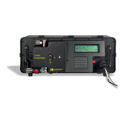
INTAKE. For
continuous flow.
Drain for discrete
samples.
EMMISION
FILTER
HOLDER.
See Appendix 8
in the user’s
manual pg. 113. WRENCH HOLDER.
Small opening in the
casting* that contains
a retainer for storing
the 5/32 Allen wrench
(used for the
Sensitivity Adjustment
Knob Lock and hex
nuts.
LIGHT CAP. Used with the Discrete
Sample Cuvette Holder. It prevents external
light from falling on the light detector. Keep in
place even when the instrument is not in
operation to prevent dirt and moisture from
entering the sample compartment.
SAMPLE COMPARTMENT. Where
Discrete Sample Cuvette Holder
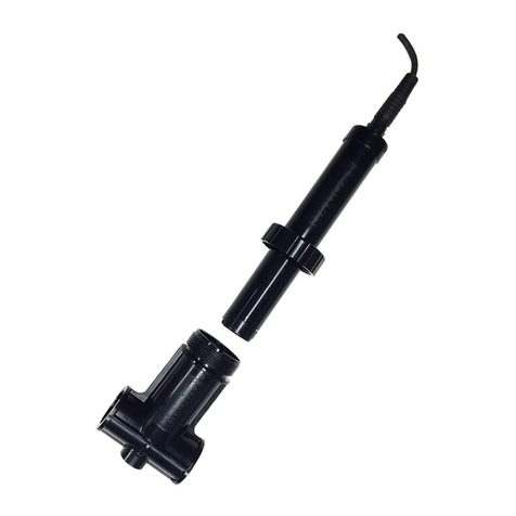
or Flow Cell (shown below) is installed.
It also contains lamp and filters.
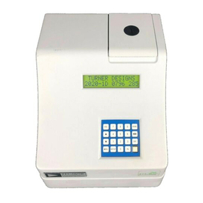
DIGITAL DISPLAY. The liquid crystal
display (LCD) shows the screens. The
backlight can be turned on by pressing any
key on the keypad. The backlight will go
off automatically when a user-set time
(from 10-3600 seconds) expires after the
last key press. Appendix 5A, screen 1.6.1.
of the user’s manual pg. 80.
Contrast of the LCD can be adjusted by
pressing the up or down arrow when on
most screens. If the screen is dark or dim
when your fluorometer is turned on check
the contrast first.
4 AMP FUSE (DC
POWER). Fuse
can be changed by
pushing in and
turning counter-
clockwise. NOTE:
There is no AC
fuse. A transformer
on the AC power
cable converts AC
to DC.
ON-OFF.
Glows red
when power
is on.
POWER/TELEMETRY
CONNECTOR. Contains
both the power input pins
and the data output pin.
An AC Power and Signal
Cable is standard with the
10-AU unless another
configuration is
requested. To supply
power, screw on the
power cable and plug into
power source. See
Appendix 11 for pin inputs
and outputs in the user’s
manual pg. 153.
SENSITIVITY ADJUSTMENT KNOB. This recessed
black screw sets the basic operating level (sensitivity) of
the instrument and is locked into position by the
Sensitivity Adjustment Lock, The level must be set
BEFORE calibrating for the first time. Thereafter, lock it
down and DO NOT adjust unless you want to change
the operating level significantly, or unless you change to
a different optical filter kit. After the initial adjustment of
this knob sensitivity will be set during calibration using
the keypad. You MUST recalibrate if the knob is
adjusted. Appendix 6B of the user’s manual pg. 92.
SENSITIVITY ADJUSTMENT LOCK.
Locks the Sensitivity Adjustment
Knob. MUST be locked to prevent
change in basic operating level and
error in readings.
KEYPAD. Used to enter new
values and to move among
screens. The left arrow can be
used as a backspace (delete)
key. If the security ID is
enabled, then 30 minutes after
the last key press, the
instrument will return to the
HOME screen. See Appendix
5A, screen 1.64 for information
about the security ID in the
user’s manual pg. 81.
Lamp
Viewport
EXCITATION
FILTER HOLDER.
See Appendix 8 in
the user’s manual
pg. 113.
Newer 10-AU’s are marked for the maximum clockwise turn rotation
with a white dot. Do not turn the locking screw past this location. *Newer 10-AU’s come with P/N 038-1201 included
in the accessory kit and do not have an opening in
the case. P/N 038-1201 has an adhesive backing
and can be secured to the 10-AU case in a
location of your choice.
INTAKE. For
continuous flow.
Drain for discrete
samples.
EMMISION
FILTER
HOLDER.
See Appendix 8
in the user’s
manual pg. 113. WRENCH HOLDER.
Small opening in the
casting* that contains
a retainer for storing
the 5/32 Allen wrench
(used for the
Sensitivity Adjustment
Knob Lock and hex
nuts.
LIGHT CAP. Used with the Discrete
Sample Cuvette Holder. It prevents external
light from falling on the light detector. Keep in
place even when the instrument is not in
operation to prevent dirt and moisture from
entering the sample compartment.
SAMPLE COMPARTMENT. Where
Discrete Sample Cuvette Holder
or Flow Cell (shown below) is installed.
It also contains lamp and filters.
DIGITAL DISPLAY. The liquid crystal
display (LCD) shows the screens. The
backlight can be turned on by pressing any
key on the keypad. The backlight will go
off automatically when a user-set time
(from 10-3600 seconds) expires after the
last key press. Appendix 5A, screen 1.6.1.
of the user’s manual pg. 80.
Contrast of the LCD can be adjusted by
pressing the up or down arrow when on
most screens. If the screen is dark or dim
when your fluorometer is turned on check
the contrast first.
4 AMP FUSE (DC
POWER). Fuse
can be changed by
pushing in and
turning counter-
clockwise. NOTE:
There is no AC
fuse. A transformer
on the AC power
cable converts AC
to DC.
ON-OFF.
Glows red
when power
is on.
POWER/TELEMETRY
CONNECTOR. Contains
both the power input pins
and the data output pin.
An AC Power and Signal
Cable is standard with the
10-AU unless another
configuration is
requested. To supply
power, screw on the
power cable and plug into
power source. See
Appendix 11 for pin inputs
and outputs in the user’s
manual pg. 153.
SENSITIVITY ADJUSTMENT KNOB. This recessed
black screw sets the basic operating level (sensitivity) of
the instrument and is locked into position by the
Sensitivity Adjustment Lock, The level must be set
BEFORE calibrating for the first time. Thereafter, lock it
down and DO NOT adjust unless you want to change
the operating level significantly, or unless you change to
a different optical filter kit. After the initial adjustment of
this knob sensitivity will be set during calibration using
the keypad. You MUST recalibrate if the knob is
adjusted. Appendix 6B of the user’s manual pg. 92.
SENSITIVITY ADJUSTMENT LOCK.
Locks the Sensitivity Adjustment
Knob. MUST be locked to prevent
change in basic operating level and
error in readings.
KEYPAD. Used to enter new
values and to move among
screens. The left arrow can be
used as a backspace (delete)
key. If the security ID is
enabled, then 30 minutes after
the last key press, the
instrument will return to the
HOME screen. See Appendix
5A, screen 1.64 for information
about the security ID in the
user’s manual pg. 81.
Lamp
Viewport
EXCITATION
FILTER HOLDER.
See Appendix 8 in
the user’s manual
pg. 113.
Newer 10-AU’s are marked for the maximum clockwise turn rotation
with a white dot. Do not turn the locking screw past this location.
INTAKE. For
continuous flow.
Drain for discrete
samples.
EMMISION
FILTER
HOLDER.
See Appendix 8
in the user’s
manual pg. 113.
INTAKE. For
continuous flow.
Drain for discrete
samples.
EMMISION
FILTER
HOLDER.
See Appendix 8
in the user’s
manual pg. 113. WRENCH HOLDER.
Small opening in the
casting* that contains
a retainer for storing
the 5/32 Allen wrench
(used for the
Sensitivity Adjustment
Knob Lock and hex
nuts.
LIGHT CAP. Used with the Discrete
Sample Cuvette Holder. It prevents external
light from falling on the light detector. Keep in
place even when the instrument is not in
operation to prevent dirt and moisture from
entering the sample compartment.
SAMPLE COMPARTMENT. Where
Discrete Sample Cuvette Holder
or Flow Cell (shown below) is installed.
It also contains lamp and filters.
DIGITAL DISPLAY. The liquid crystal
display (LCD) shows the screens. The
backlight can be turned on by pressing any
key on the keypad. The backlight will go
off automatically when a user-set time
(from 10-3600 seconds) expires after the
last key press. Appendix 5A, screen 1.6.1.
of the user’s manual pg. 80.
Contrast of the LCD can be adjusted by
pressing the up or down arrow when on
most screens. If the screen is dark or dim
when your fluorometer is turned on check
the contrast first.
4 AMP FUSE (DC
POWER). Fuse
can be changed by
pushing in and
turning counter-
clockwise. NOTE:
There is no AC
fuse. A transformer
on the AC power
cable converts AC
to DC.
ON-OFF.
Glows red
when power
is on.
POWER/TELEMETRY
CONNECTOR. Contains
both the power input pins
and the data output pin.
An AC Power and Signal
Cable is standard with the
10-AU unless another
configuration is
requested. To supply
power, screw on the
power cable and plug into
power source. See
Appendix 11 for pin inputs
and outputs in the user’s
manual pg. 153.
SENSITIVITY ADJUSTMENT KNOB. This recessed
black screw sets the basic operating level (sensitivity) of
the instrument and is locked into position by the
Sensitivity Adjustment Lock, The level must be set
BEFORE calibrating for the first time. Thereafter, lock it
down and DO NOT adjust unless you want to change
the operating level significantly, or unless you change to
a different optical filter kit. After the initial adjustment of
this knob sensitivity will be set during calibration using
the keypad. You MUST recalibrate if the knob is
adjusted. Appendix 6B of the user’s manual pg. 92.
SENSITIVITY ADJUSTMENT LOCK.
Locks the Sensitivity Adjustment
Knob. MUST be locked to prevent
change in basic operating level and
error in readings.
KEYPAD. Used to enter new
values and to move among
screens. The left arrow can be
used as a backspace (delete)
key. If the security ID is
enabled, then 30 minutes after
the last key press, the
instrument will return to the
HOME screen. See Appendix
5A, screen 1.64 for information
about the security ID in the
user’s manual pg. 81.
Lamp
Viewport
EXCITATION
FILTER HOLDER.
See Appendix 8 in
the user’s manual
pg. 113.
Newer 10-AU’s are marked for the maximum clockwise turn rotation
with a white dot. Do not turn the locking screw past this location.
Newer 10-AU’s are marked for the maximum clockwise turn rotation
with a white dot. Do not turn the locking screw past this location. *Newer 10-AU’s come with P/N 038-1201 included
in the accessory kit and do not have an opening in
the case. P/N 038-1201 has an adhesive backing
and can be secured to the 10-AU case in a
location of your choice.
*Newer 10-AU’s come with P/N 038-1201 included
in the accessory kit and do not have an opening in
the case. P/N 038-1201 has an adhesive backing
and can be secured to the 10-AU case in a
location of your choice.

