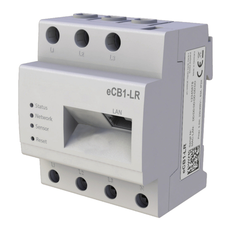
Hardy Barth eCB1-LR Quick guide

Smartmeter
eCB1-LR
Configuraon instrucons
Configuration instructions eCB1
smartmeter
Version: 1.2.3
1
English

Table of contents
Contact data...............................................................................................................3
General infomaon about the eCB1............................................................................4
Note.................................................................................................................................................4
Meaning of the LED states...............................................................................................................4
Reset funkon..................................................................................................................................4
Setup of direct LAN connecon to the eCB1...............................................................4
Connecng the BUS connecon between wallbox and eCB1......................................7
Configuraon of the eCB1 LR MP+ (metering point)...................................................8
Open the Webinterface...................................................................................................................8
Language und region.......................................................................................................................9
Date und e..................................................................................................................................9
Network se"ngs............................................................................................................................10
Internal...........................................................................................................................................11
Charge connector 1........................................................................................................................12
Finish setup....................................................................................................................................12
Explanaon of the web interface (PV load control)...................................................14
Configuraon of the eCB1 LR PV (PV load control)....................................................15
Language und region.....................................................................................................................15
Date und e................................................................................................................................16
Network se"ngs............................................................................................................................17
House connecon..........................................................................................................................18
Charge connector 1........................................................................................................................20
Setup co pleon...........................................................................................................................22
Fir ware update............................................................................................................................23
I portant se"ngs for operaon...................................................................................................23
Charge-Log.....................................................................................................................................26
Warranty / Guarantee...............................................................................................28
Guarantee specificaons and warranty.........................................................................................28
Notes........................................................................................................................30
Configuration instructions eCB1
smartmeter
Version: 1.2.3
2

Contact data
manufacturer: eCHARGE Hardy Barth GmbH
Leinbergstraße 14
92262 Birgland-Schwend
telephone: +49 9666 188 13 0
telefax: +49 9666 188 13 1
web: www.echarge.de
mail: support@echarge.de
Configuration instructions eCB1
smartmeter
Version: 1.2.3
3

General infomation about the eCB1
Note
To prevent confusion between the different models, please refer to the version of the
device marked on the packeging. The installation and configuration should be carried
out in the specified order.
Meaning of the LED states
Status-LED
•
permanent green The eCB1 is ready for operation.
•
Slowly flashing in green The device starts.
•
Quickly flashing in green A firmware update is running.
•
glowing or flashing in red or An error occured.
orange
Network-LED
•
Off no connection
•
permanent green connection active
•
green flashing network activity
Bus-LED
•
Off device is not configured
•
green connection is ok
•
orange no device detected
•
red BUS error
Reset funktion
You can reset the eCB1 to network settings or simply restart the device by pressing the
reset button. The time period of pressure applied is important.
Reset to factory settings
With a pointy ob ect, press the reset button for 4 to 10 seconds.
Restart the eCB1
To restart, use a pointy ob ect to press the reset button for 1 to 3 seconds.
Setup of direct LAN connection to the eCB1
Configuration instructions eCB1
smartmeter
Version 1.2.3
4

Step 1: Install the eCB1 and connect it to the power supply.
Step 2: Connect the eCB1 to your network, a PC or laptop using a LAN cable see
diagram).
Please note: Make sure that only one unconfigured eCB1 is connected in your network to
avoid name collisions.
1. Start your browser
2. Type in the following URL „http://ecb1.local“ see image below).
→ The user interface of the eCB1 opens.
If the user interface does not open, please check the following points:
1. Name resolution does not work
Configuration instructions eCB1
smartmeter
Version: 1.2.3
5
Connect the eCB1 to your
network using a LAN cable
and insert it into the LAN
port of the eCB1.
Connect your PC/laptop with
your network/router by
inserting the LAN cable into
the LAN port.

Access the user interface using the current IP address of the eCB1.
„(http://<IP>/)“
To do this, ca up the router´s user interface and read the IP address of the eCB1 (see
manua of your router).
If you have Windows XP/7/8: insta App e Bonjour® . You can find the donw oad ink on
www.app e.com. Then enter the URL again.
Note: App e Bonjour® is a so inc uded in App e iTunes®.
A ternative y contact the network administrator.
2. The status LED does not glow
If the status LED of the eCB1 does not g ow, it means that
the smartmeter is not provided with any power.
P ease make sure that at east one of the phase conductos
L1 and the neutra conductor N are connected to the eCB1.
3. The status LED glows or blinks red
If the status LED g ows or b inks red, an error has occured.
P ease restart the eCB1 by pressing the reset button
with a pointy objet for about to 3
seconds.
4. The Network-LED does not glow
If the network-LED does not g ow, the network cab e is not proper y/correct y connected to
the network port. P ease make sure that you have inserted both ends of the cab e proper y
and correct y.
5. eCB could not be found in the network
In this case the eCB1 is not ocated in the same oca network. P ease connect the
eCB1 with the same Router/Switch as the one of your PC’s/ aptop’s.
If that does not so ve your prob em, p ease reset the eCB1 to its factory settings by
pressing the reset button with a pointy object for about 4 to 0 seconds.
Configuration instructions eCB
smartmeter
Version: 1.2.3
6

Connecting the BUS-connection between wallbox
and eCB1
Image 1: shows the BUS-clamps of the cPµ1.
Image 2: shows the BUS-clamps of the eCB1.
(Please note the green marks in Image )
hese have to be connected as follows:
- Plug the brown wire (second slot on the eCB1) in
„1“ (shown in Image 1).
- Plug the black wire (third slot on the eCB1) in
„2“.
- Last step you plug the blue wire (first slot on the
eCB1) in „3“.
Configuration instructions eCB1
smartmeter
Version: 1.2.3
7
1
2
1

Configuration of the eCB1 LR MP+ (metering
point)
Open the Webinterface
Open the Webinterface of the eCB1 MP+ (metering point at the house connection) by
entering its IP address in your webbrowser
Prior to that, it has to be integrated into the network of the house Then through the
interface of the router, you can find the IP address of all eCB1, including this one
If therer is no other configured eCB1 in your Network you can contact the eCB1 MP+ with
http://ecb1 local for first configuration
If the Domane Name System does not work you can find the IP adress through the
Webinterface of your router
The following page should open up:
Please click “proceed” to get to the following section:
Configuration instructions eCB1
smartmeter
Version: 1.2.3
8

Language und region
Here you can set:
–the language
–the country in which you are installing the charging station and
–the time zone
Date und time
Click “proceed” to get the following screen:
Here you can set the time and date manually or automatically.
Configuration instructions eCB1
smartmeter
Version: 1.2.3
9

Manual setting
Click on the date button and select the desired date from the calendar. Then click the
time button and enter the current time.
Please separate the hours, minutes and seconds with colons.
To complete the settings, press “Set time” and the settings will be saved.
Automatic setting
In this case “Date” and “Time” do not need an entries.
There are pre-set internet pages in section “NTP Server 1” and “NTP Server 2”. These will
connect ou automaticall with a time server.
Click on “Set time by ntp” to save our settings.
If ou want to connect with a different, or our own time server, please enter the internet
address manuall .
B clicking “automatic synchronise at boot”, the time will be s nchronised automaticall
after ever outage (power, network, etc.).
After completion of the time and date settings, click on “proceed” to get to the next
section.
Network settings
If ou choose “DHCP” as protocol:
Your DHCP-Server (e. g. router) will do
further settings automaticall and fill the
remaining blank spaces.
There are no other settings to be made in
the section except selecting a hostname.
Please select a distinct host name.
The device should respond to the given
hostnamen (givenname.local). Upon deliver
the hostname given is „ecb1 local“.
Configuration instructions eCB1
smartmeter
Version: 1.2.3
10

If you select „static“ for protocol:
You have to enter the network settings
manually. Contact your network
configurator to fill in the corresponding
fileds in a network-compatible manner.
Internal
In this section you will determine the function of the eC 1. As you are configuring an eC 1
metering point that is installed at the house connection please choose the device function
„building service head“.
Configuration instructions eCB1
smartmeter
Version: 1.2.3
11

You can name the eCB1 MP+ “house_connection_eCB1” to prevent confusing it with
other installed eCB1.
The utton “measurement via current transformer” must only e activated when there is a
measuring transformer installed. Press on the utton to activate (orange) and deactivate
(grey). Usually ( y German law) a measuring transformer is required when the house
connection exceeds 63A.
Charge connector 1
In this case, the eCB1 LR MP+ is responsi le for the measurement at the house
connection and does not require a charging point.
Choose „No EVCC“ (EVCC = charge controller).
Press „proceed“ to finish the seutup.
Finish setup
Configuration instructions eCB1
smartmeter
Version: 1.2.3
12

Click on the button „finish Setup“.
After finishing the setup, the device restarts to save all the settings.
The web interface will open automatically after the restart.
Should no interface appear after five minutes, please refresh the page or enter the P-
address again.
The setup finish ends the configuration process of the eCB1 LR MP+ and you can start to
configurate the other eCB1.
Configuration instructions eCB1
smartmeter
Version: 1.2.3
13
eCB1 reboot in progress...

Explanation of the web interface (PV load control)
ECO-Charging Ensures minimum charge through a PV-System and/or with
power from the power supply net if needed. Purchase of energy
from power supply net is only the case if AI-Mode is deactivated.
AI-mode nly available if EC -Charge Mode is activated (button will be
marked in orange). In AI-Mode the charging process will
automatically start in case of surplus PV-power or turn off when
there is too little PV-power. For this, section „Eco Min-Max
Ampere“ in the later configuration is the most important setting.
Fast charging Charge with maximum capacity of the charging station.
Manual charging Set the charging power manually.
Start charging Start the charging process.
Stop charging Stop the charging process.
Current charging
graph
Shows the current power output at the house connection as well
as single power graphs of the charger connection.
Configuration instructions eCB1
smartmeter
Version: 1.2.3
14

Configuration of the eCB1 LR PV (PV load control)
Open the web interface.
Click “Proceed” to get to the following selection:
Language und region
Here you can set:
- the language
- the country in which you are installing the charging station and
- the time zone
Configuration instructions eCB1
smartmeter
Version: 1.2.3
1

Date und time
Click “proceed” to get the following screen:
Here you can either set the date and time manually or have it set automatically.
Manual setting
Click on the Date button and choose the current date. Then continue with the Time
button to enter the current time.
Please separate the hours, minutes and seconds with colons.
To complete the settings, press “Set time” and the settings will e saved.
Automatic setting
In this case “Date” and “Time” do not need any entries.
There are pre-set internet pages in section “NTP Server 1” and “NTP Server 2”. These will
connect you automatically with a time server.
Click on “Set time by ntp” to save your settings. If you want to connect with a different, or
your own time server, please enter the internet address manually.
By clicking “automatic synchronise at boot”, the time will e synchronised automatically
after every interruption (power, network etc.).
Configuration instructions eC 1
smartmeter
Version: 1.2.3
16

Network settings
After completion of the time and date settings, click “proceed” to get to the next section.
If you choose “DHCP” as protocol.
Your DHC -Server (e. g. router) will do
further settings automatically and fill the
remaining blank spaces.
There are no other settings to be made in
the section except selecting a hostname.
lease select a distinct host name.
The device should respond to the given
hostnamen (givenname.local). Upon delivery
the hostname given is „ecb1.local“.
If you select „static“ for protocol
You have to enter the network settings
manually. Contact your network configurator
to fill in the corresponding fileds in a
network-compatible manner.
Configuration instructions eCB1
smartmeter
Version: 1.2.3
17

House connection
Please click “proceed” to get to the following section:
In this case: A Fronius smartmeter is already installed on the house connection, which
can be read out via the Fronius inverter.
Measurement via current transformer
Only activate “measurement via current transformer” when a current transformer is
installed. his usually is only the case when the house connection exceeds 63 A.
If an eCB1 LR MP+ has already been installed and this setting has already been chosen
for the first device during the earlier described configuration process (see page 11), it is
not necessary to activate it again.
Configuration instructions eCB1
smartmeter
Version: 1.2.3
18

Selection variants device type/manufacturer
eCB1 (internal) an eCB1-LR PV is installed at the house connection
another eCB1 an eCB1-LR MP+ is installed at the house connection
B-control Energy
Manager
a B-Control Energy Manager (EM 100, EM 210, EM
00) is installed at the house connection
SMA Energy Meter a SMA Energy Meter or a Home Manager 2.0 is
installed at the house connection
ronius measuring point a Fronius smartmeter is installed which can be read
via the Fronius inverter.
Kostal measuring point a Kostal smartmeter is installed at the house
connection
Janitza UMG power
quality analyser
a Janitza UMG network analyser is installed at the
house connection
KLE R 6934 Meter a KLEFR Energy Meter is installed at the house
connection
PHOENIX CONTACT
measuring point
a Phoenix Contact measuring point is installed at the
house
Passive push updated
measuring point
via http Post (via API gateway) updated measuring
point
No measuring point There is no measuring point installed*
*If no device is installed at the house connection “no measuring point” ca be chosen.
Then the house connection stays deactivated and no input is saved.
Note: In this case it´s not possible to enable a PV-regulated load or a house connection
limit.
Click “proceed“ to get into the next section.
Configuration instructions eCB1
smartmeter
Version: 1.2.3
19

Charge connector 1
Select the device type that is installed in the charging station for current
measurement here.
Selection variants device type/manufacturer
eCB1 (internal) an eCB1 PV is built in the charging
station → for PV load control
KLE R Energy Meter KLEFR Energy Meter is installed as
measuring oint in the charging station
Phoenix Contact Messpunkt Phoenix Contact measuring oint is
instaled in the charging station
Configuration instructions eCB1
smartmeter
Version: 1.2.3
20
Other manuals for eCB1-LR
1
Table of contents
Other Hardy Barth Measuring Instrument manuals
Popular Measuring Instrument manuals by other brands

Dynojet
Dynojet DynoWare RT 250i installation guide
Endress+Hauser
Endress+Hauser SpectraSensors SS2100i-1 Safety manual
Apera Instruments
Apera Instruments TN400 instruction manual
E-Mon
E-Mon Din-Mon D5 installation instructions
Jolly logic
Jolly logic ALTIMETERONE How to use
steute
steute RF 96 BU SW868-NET-LDS Mounting and wiring instructions
