Hardy Diagnostics IncuPRO 133000H User manual

IFU - XXXXX
IncuPRO Incubator
Model
133000H
Operating Instructions

IFU – XXXXX Page 1of 8
CONTENTS
Page
1.0 Safety and Precautions.................................................................................2
2.0 Product Information......................................................................................3
3.0 Assembly.......................................................................................................3
3.1 Unpacking.................................................................................................3
3.2 Installation ................................................................................................3
4.0 Operation........................................................................................................4
4.1 Controls and Indicator Lamps...................................................................4
4.2Setting the Temperature...........................................................................4
4.3 Operating the Incubator............................................................................5
5.0 Accessories....................................................................................................5
6.0 Fault Diagnosis ..............................................................................................5
7.0 Technical Specifications ...............................................................................5
8.0 Maintenance and Service .............................................................................6
8.1 Cleaning ...................................................................................................6
8.2 Replacement of Fuses..............................................................................6
9.0 Warranty.........................................................................................................7
10.0 Service ...........................................................................................................7

IFU – XXXXX Page 2of 8
1.0 Safety and Precautions
The following symbols marked on the equipment mean:
Caution: Read these operating instructions fully before use and pay particular
attention to sections containing this symbol.
Attention: Suivre attentivement les instructions avant l’usage et prêtez une
attention particulière aux sections comportant ce symbole.
Caution: Surfaces can become hot during use.
Attention: Les surfaces peuvent devenir brûlantes pendent l’usage.
Always observe the following safety precautions:
•Use only as specified by the operating instructions. After transport or
storage in humid conditions, dry out the unit before connecting it to the
supply voltage. During the drying out period, the intrinsic protection may
be impaired.
•Connect only to a power supply with a voltage corresponding to that on
the serial number label.
•Connect only to a power supply that provides a safety ground terminal.
•Before moving, disconnect at the power supply socket. Do not remove the
plug from the rear of the unit.
•Do not check the temperature by touch, but instead use the temperature
display.
•To reduce the risk of eye injury during high temperature operation, use
safety goggles or eyeglasses.
•Do not touch surfaces that become hot during high temperature operation.
•Ensure that the operating temperature is less than the maximum operating
temperature of your sample material.
•Ensure that the power switch is easily accessible during use.
•If liquid is spilled inside the unit, disconnect it from the power supply and
have it checked by a competent technician.
•It is the user’s responsibility to carry out appropriate decontamination if
hazardous material is spilled on or inside the equipment.
•This product must be used with a UL Listed / CSA Certified power supply
cord rated for a minimum temperature of 90˚C.
•If the equipment is used in a manner not specified by the manufacturer,
the protection provided by the equipment may be impaired.

N2400386 IFU - XXXXX
3
2.0 Product Information
The Hardy IncuPRO Incubators are designed for laboratories and clinics that
require contemporary styling, accuracy, and economy in a basic incubator
package. The incubator uses a dial controlled thermostat and has the added
features of a digital temperature display and a double walled chamber door. The
incubator has a chamber volume of 0.8 cu. ft. (0.02 cu.m) and a chamber
temperature range of ambient +5˚C to 60˚C. The incubator has a chamber
uniformity of +/- 1˚C at 37˚C within the bounds of the shelf area.
3.0 Assembly
3.1 Unpacking
Remove packing materials carefully, and retain for future shipment or
storage of the unit. Inspect for damage. Report all shipping damage to
the carrier immediately. Shipping damage is covered by the carrier and
repair/replacement for shipping damages must be coordinated through the
carrier. Complete and return the Warranty Registration Card. Packs
should contain:
•133000H Incubator
•Power Line Cord
•Operating Instructions
•Two Shelves
•Eight Shelf Brackets
3.2 Installation
Place the Incubator on a flat and stable surface, preferably away from
drafts. Ensure that the surface on which the unit is placed will withstand
the radiated heat produced by typical laboratory incubators. Fit the power
line cord into the IEC power socket on the rear of the unit. Plug power
cord into a power supply that matches the voltage listed on the serial
number label on the rear of the unit.
Insert the wire rack shelves at the desired heights. Refer to the sketch
below for proper shelf bracket installation.
N2400386 IFU - XXXXX
4
4.0 Operation
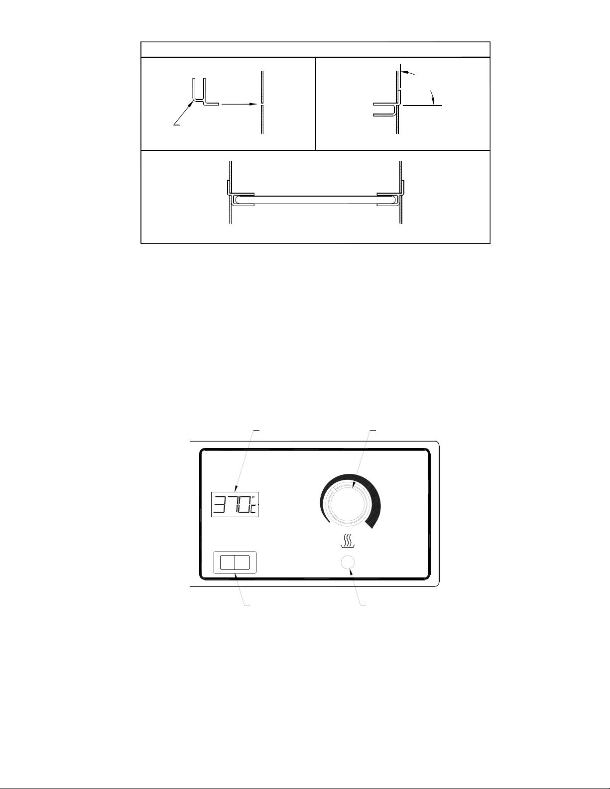
4.1 Controls and Indicator Lamps (see Figure below)
The power switch controls power to the unit.
The temperature display shows the chamber temperature in degrees
Celsius.
The heater lamp indicates when the heater is operating.
The temperature adjust knob is used to control the chamber temperature.
Temperature
Adjust Knob
Power
Switch
OI
Heater
Lamp
Temperature
Display
4.2 Setting the Temperature
Use the temperature adjust knob to set the desired temperature. The
knob is rotated clockwise to increase the chamber temperature and
counter-clockwise to decrease the chamber temperature.
SHELF INSTALLATION DIAGRAM
SHELF
BRACKET
INNER
WALL
STEP #1
STEP #3
SHELF
STEP #2
90°
INNER
WALL
INNER
WALL
WALL
INNER

N2400386 IFU - XXXXX
5
4.3 Operating the Incubator
To turn the incubator on, switch the power switch to the on (I) position.
Set the desired chamber temperature. The heater lamp will illuminate and
remain lit until the chamber reaches the set temperature. After reaching
the set temperature, the heater lamp will cycle on and off with heater
operation. Allow a 60 minute chamber temperature equilibration when
starting the incubator from a cold start. Allow at least 15 minutes for the
re-equilibration when changing temperatures. To turn the incubator off,
switch the power switch to the off (O) position. If the temperature adjust
knob is not moved when the incubator is powered down, the incubator will
return to its previously set temperature upon restart.
5.0 Accessories
5.1 Removable Shelf – Catalog Number C1902053
5.2 Shelf Bracket – Catalog Number A1903208
6.0 Fault Diagnosis
Symptom
Possible Cause
Action Required
1. Unit does not operate
a. Unit not switched on
b. Unit not plugged into
power supply
c. Fuses blown
d. Power supply failure
a. Switch on
b. Plug in, switch on
c. Replace fuses per 8.2
d. Check that other
electrical appliances on
the same circuit are
working
2. Chamber temperature
does not rise when
expected
a. Actual temperature is
higher than set
temperature
b. Temperature control
circuit fault
a. Check set temperature
b. Have unit checked by
competent person
3. Temperature continues
to rise when not
expected
a. Actual temperature is
lower than set
temperature
b. Temperature control
circuit fault
a. Check set temperature
b. Have unit checked by
competent person
7.0 Technical Specifications
This equipment is intended for indoor use and will meet its performance figures
within the ambient temperature range of 10°C to 35°C, with maximum relative

N2400386 IFU - XXXXX
6
Fuse
Drawer
humidity of 80% (non-condensing). Installation Category II (transient voltages).
Pollution Degree 2 in accordance with IEC 664. Suitable for operation at
altitudes of up to 6500 feet.
Specifications:
Temperature Range: (Ambient +5°C) to 60°C
Temperature Uniformity: +/- 1°C at 37°C
Temperature Display Resolution: 0.1°C
Supply Voltage Range: 120V +/- 10%, 50/60 Hz
Power Rating: Model 133000H: 90W
8.0 Maintenance and Service
The IncuPRO is designed to comply with IEC1010-1. No routine maintenance is
required. There are no user serviceable parts in this product. There are no
additional parts that are required to be examined or supplied by Hardy
Diagnostics.
8.1 Cleaning
Disengage power cord prior to cleaning. If a spill occurs, use appropriate
clean up procedures as required for radiation or biohazard control. The
outer casing may be cleaned with water and a damp cloth. Do not
submerge or immerse the Incubator in water. Before using any cleaning
or decontamination method except those recommended by the
manufacturer, users should check that the proposed method would not
damage the equipment.
8.2 Replacement of Fuses
There are two supply fuses located in the fuse drawer. To change the
fuses:
•Turn power switch to the off position
•Disconnect the unit from the power supply
•Remove the line cord from the power entry module on the back of
the unit
•Pull back on the fuse drawer (see sketch below)
•Pull out the fuse drawer
•Check and replace with the correct fuses if necessary. The fuses
should be 5mm x 20mm quick acting, rated 250V. Model
133000H (115 V AC): 1AF.
•Push the fuse drawer back in. Reconnect unit to power supply.

N2400386 IFU - XXXXX
7
9.0 Warranty
When used in laboratory conditions and according to these operating
instructions, Hardy Diagnostics warrants this product to be free of defective
material and workmanship for a period of two years from the date of
manufacture. The liability of Hardy Diagnostics for any defective equipment
during the warranty period shall be limited to the repair of such equipment or
replacement thereof without charge for parts or labor.
10.0 Service
It is required to obtain a Returned Material Authorization (RMA) number before
any Hardy Diagnostics products are returned for any reason. A Decontamination
Certificate must be completed, signed by the user, and returned to Hardy
Diagnostics prior to receiving the RMA number. Please be sure to mark the
outside of the returned goods package with this RMA number to ensure prompt
handling.
Manufactured for
Hardy Diagnostics
1430 McCoy Lane
Santa Maria, CA 93455
Phone: (805) 346-2766
Technical Support: (800) 266-2222 (option 2)
E-mail: TechnicalServices@HardyDiagnostics.com
Website: www.HardyDiagnostics.com
Table of contents
Other Hardy Diagnostics Accessories manuals


