Hardy HL-1000 User manual

HL-1000 Operator’s Manual
The Missing Link that Transfers Work from Man to Machine.
This operator manual has information for the HL-1000 machine plus optional upgrades.
Some illustrations and information may not pertain to your model.
WARNING
1The Missing Link that Transfers Work from Man to Machine.
WARNING
YOU MUST BE TRAINED.
Do not operate this machine until you have been trained and
approved by your employer.
Never make repairs without authorization and always refer to
manuals before servicing.
If you suspect shipping damage, please do not unpack,
instead take pictures and contact the shipping company.
Follow their instructions on what to do next.
Before removing your HL-1000 from the pallet, please
carefully remove all banding, packing and shipping.

CONTENTS / WHAT’S IN IT FOR YOU?
2 The Missing Link that Transfers Work from Man to Machine.
WHAT’S IN IT FOR YOU?
The better you understand your machine and how to use it, the better and safer operator you
can be. Here are some tips to using this manual.
QUICK LOCATORS
In addition to the “Contents” page you can use
page headings to find topics.
“KNOW THE HAZARDS”
Watch for and read these special blocks.
You will find information about safety tips.
DRAWINGS
On many pages you will find pictures as
well as text to help you understand how to
use your machine safely and productively.
Warning
Contents / What’s in it for You?
HL-1000
HL-1000 Tiller Head
Vin Plate
Power / Charging
Raising & Lowering / Steering
Driver’s Safety
Daily Safety Check /
Be a Safe Operator
Maintenance / Battery Box Cover
General Info
Daily Checklist
Maintenance Checklist
Cut Sheets/Manuals
1
2
3
4
5
6
7
8
9
10
11
12
13
14
CONTENTS

HL-1000
3The Missing Link that Transfers Work from Man to Machine.
HL-1000
TILLER HEAD
VIN PLATE
BATTERY BOX
COVER
TILLER HANDLE
DRIVE WHEEL
CAR
ATTACHMENT
MAST
PICKING POINT
HL-1000 TILLER HEAD
4The Missing Link that Transfers Work from Man to Machine.
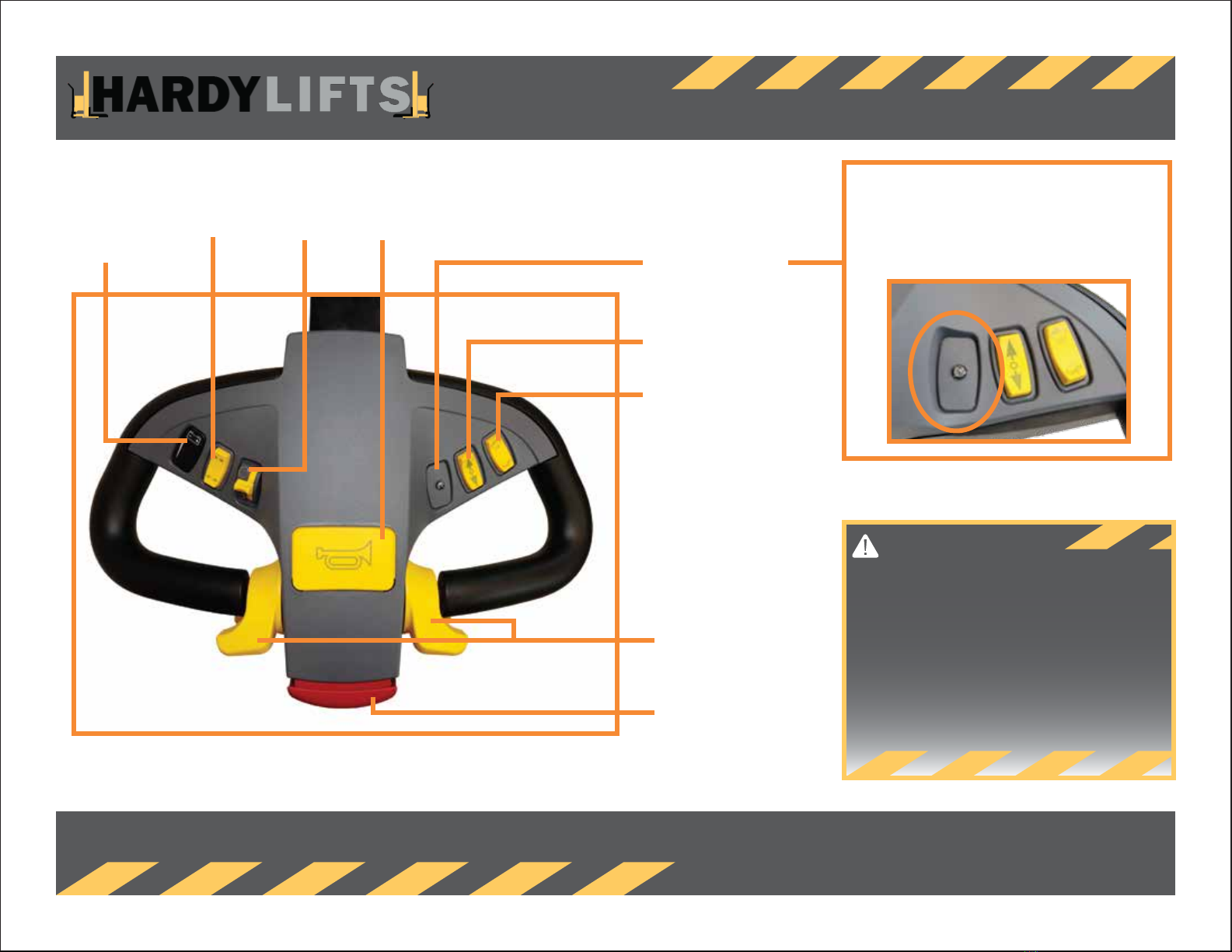
HL-1000 TILLER HEAD
BATTERY STATUS
INDICATOR
ACTUATOR ROTATE HORN
EMERGENCY BRAKE
INDICATOR
RAISE/LOWER
SPEED CONTROL
THROTTLE WHEEL
BELLY BUMP
Know the Hazards
Before using the HL-1000 in the work area, practice
driving it, without a load, in a safe area until you are
comfortable with maneuvering the HL-1000.
Always be aware that this is equipment. Hands or
feet caught between moving parts of the the
HL-1000 are subject to injury.
EMERGENCY BRAKE INDICATOR
If this light is illuminated the emergency brake is
engaged. To release brake, find the bar on the side
of the drive wheel and release brake.

VIN PLATE
5The Missing Link that Transfers Work from Man to Machine.
Know the Hazards
You must read and understand warnings on VIN Plate before operating the HL-1000.
MODEL
The model of your machine.
SERIAL
The serial number for your specific
machine.
LIFTING CAPACITY
The amount of weight the machine itself
can lift. Attachments have different load
regulations, refer to attachments
specifically for their capacity.
GROSS VEHICLE WEIGHT
The full weight of the vehicle, minus
attachment and load weights.
CHARGING VOLTAGE
The required wall charger requirements.
120 VAC required to charge HL-1000.
BATTERY VOLTAGE
Operating voltage of machine is 24 VDC.
KNOW YOUR LOAD
Know your load. Do not exceed the capacity shown on the HL-1000’s VIN Plate.
Make sure you do not overload machine or attachments.
Gross Vehicle Weight is the weight of the vehicle only. Some docks, elevators and
floors have a weight limit. Remember to add the weight of your load on the
machine.

POWER / CHARGING
6The Missing Link that Transfers Work from Man to Machine.
POWER - KEY SWITCH
Your key switch is located on the head at the base.
KEY IN UPRIGHT POSITION
TURN-ON
Turn the machine on by
switching the key to the
right. Pause a moment before
operating to allow the machine
to boot up.
KEY IN UPRIGHT POSITION
Turn the machine off by
switching the key back left
to the upright position.
Always turn the key off
when machine is not in use.
CHARGING
Plug in the machine when not in use.
The on-board trickle charger will keep the batteries from ‘over charging’.
Machine is charged via the charge port on the side of the machine and a
standard 120V wall outlet.
RAISING & LOWERING / STEERING
7The Missing Link that Transfers Work from Man to Machine.
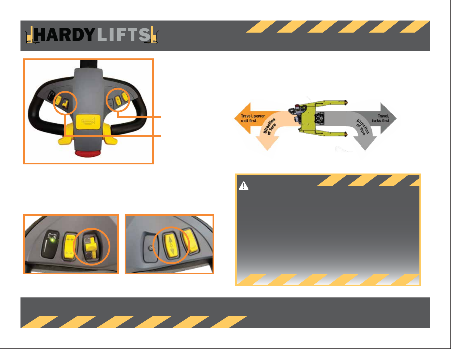
RAISING/LOWERING/TURNING ATTACHMENT
To raise the attachment, press the top of the arrows button.
To lower the attachment, press the bottom of the arrows button.
To rotate the attachment, push the rotate button in the direction you
want to turn the load.
STEERING
You control the steering by moving the tiller handle from side to side. Always travel with a
load as close to the ground as possible.
Know the Hazards
When driving, make sure you know your turning radius and are clear of people and
objects in your travel path.
Make sure to practice without a load, and in a safe area, before using for tasks.
Always take caution when using on an uphill/downhill surface. The HL-1000 was
not designed for inclines/declines and machine may shift, tip or handle differently.
Do not allow load to sway or swing from machine.
RAISING/LOWERING BUTTONROTATE BUTTON
RAISING/LOWERING
BUTTON
ROTATE BUTTON

DRIVER’S SAFETY
8The Missing Link that Transfers Work from Man to Machine.
DRIVE
To drive the HL-1000, roll throttle wheel forward to go forward, roll throttle wheel back to reverse the machine.
To stop the machine, let go of the throttle wheel.
The rabbit will increase and the turtle will decrease your top speed respectively.
HORN
A horn is standard on the top of the tiller head. If you need to warn people you are
traveling, coming to a doorway, etc, simply press the horn button and release.
This is not a constant on horn.
Know the Hazards
Always be aware of your surroundings when
operating machinery.
Know where people, objects, and flooring changes are.
BELLY BUMP
To keep you from becoming accidentally trapped between an object and the machine, the
HL-1000 is equipped with a belly bump safety switch. Located at the end of the tiller head.
when the red button is depressed it will instantly stop the machine and reverse it slowly
away from you for a short time before coming to a stop.
DAILY SAFETY CHECK / SAFE OPERATOR
9The Missing Link that Transfers Work from Man to Machine.
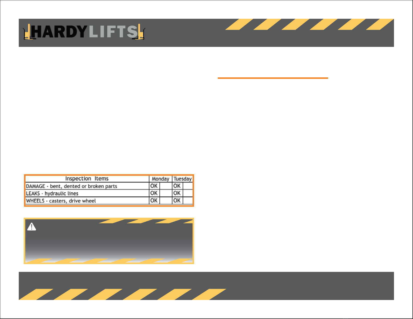
DAILY SAFETY CHECK
This manual comes with a daily safety check log. This is meant to be used before every shift,
in a safe environment. This is to serve as a quick reminder to check the status of the
HL-1000. If anything ever looks, or acts odd, please do not use the machine until it has
been looked at and returned to service.
The daily safety check is not intended to be invasive and is mostly an eyes-only scan of the
machine. Please DO NOT remove the battery box cover unless you are authorized to do so.
Mishandling of the electrical system can result in a shock hazard or even a machine fire.
The Operator’s Daily Checklist can be found at the end of this manual and is available for
printing. Please check the OK box if things are fine or the blank box if something needs
attention. At the bottom of the column is a place to initial that you performed the checks.
There is also a space for additional comments.
DAILY SAFETY CHECK EXAMPLE
Know the Hazards
Performing visual checks, physical checks and maintenance of the machine will
help in avoiding hazards in the workplace.
BE A SAFE OPERATOR
The most important part of safety is you.
Do not use the HL-1000 until you feel safe and secure in using it and are approved by
your employer.
Make sure you understand how the HL-1000 works, handles and operates in your
environment.
Make sure you adhere to the HL-1000, and attachments, lifting capacities.

MAINTENANCE / BATTERY BOX COVER
10 The Missing Link that Transfers Work from Man to Machine.
MAINTENANCE
This manual come with a checklist for required maintenance, but always watch for items
that may wear over time/usage.
Please make sure the required maintenance is done per the schedule. Always refer to the
attached cut sheets/manuals for the part you are working on before performing the
required maintenance.
Troubleshooting videos via www.hardylifts.com/support are a good resource.
Always make sure to fill out the “Hour Meter Reading” column on the maintenance checklist
and keep a copy onsite.
The Required Maintenance Checklist has extra rows for adding your own required
maintenance. For example, the machine will be used in a dirty area, regular cleaning may
be required. Checking things such as the condition of caster wheels, screws, wires, etc.
is always a good idea, but frequency really is site specific.
MAINTENANCE CHECKLIST EXAMPLE
BATTERY BOX COVER
Inside the batery box cover is the hydraulic power unit, the full electrical system and the
drive/rotate cards. Please do not perform maintenance here without authorization and
knowledge of what you are dealing with. Improper adjustments can cause shock or fire
hazards.
If you are qualified, please refer to www.hardylifts.com/support for
troubleshooting videos.

GENERAL INFORMATION
11 The Missing Link that Transfers Work from Man to Machine.
GENERAL INFORMATION
For replacement parts and troubleshooting, please first visit our website at www.hardylifts.com
There is a Parts Store and a link to our troubleshooting videos.
GENERAL WARNING
HardyLifts is not responsible for any damage that may occur during operation of this machine.
Operators should not be under the influence of any drugs or alcohol when operating this machine.
All company safety protocols should be adhered to.
Usage outside of the intended purpose of the machine will void any warranty agreements with HardyLifts.
LIFTING CAPACITIES
The HL-1000 is designed to lift 1,000 lbs two inches (2”) off the mast. For lifting capacities of attachments,
please refer to the attachments book.
MAINTENANCE WARNING
Before performing any maintenance, ensure attachment is lowered all the way to the ground and power is off to the machine.

HL-1000 Daily Checklist
12 The Missing Link that Transfers Work from Man to Machine.
INSPECTION ITEMS MONDAY TUESDAY WEDNESDAY THURSDAY FRIDAY SATURDAY SUNDAY
DAMAGE - bent, dented or broken parts OK OK OK OK OK OK OK
LEAKS - hydraulic lines
WHEELS - casters, drive wheel
ATTACHMENTS - secured, not cracked or badly worn
CHAINS, CABLES & HOSES - in place, no cracks or pinch
GUARDS - safety shields/guards in place
CONTROLS - tiller head/pendant in good condition
ELECTRICAL SAFETY - key on/off, belly bump, horn
STEERING - wheels move freely, no binding
HYDRAULICS - all function smoothly
OK OK OK OK OK OK OK
OK OK OK OK OK OK OK
OK OK OK OK OK OK OK
OK OK OK OK OK OK OK
OK OK OK OK OK OK OK
OK OK OK OK OK OK OK
OK OK OK OK OK OK OK
OK OK OK OK OK OK OK
OK OK OK OK OK OK OK
OK OK OK OK OK OK OK
OK OK OK OK OK OK OK
OPERATOR’S INITIALS
SUPERVISOR’S INITIALS
COMMENTS: (Items needing inspection/replacement)
OPERATORS DAILY CHECKLIST
WEEK BEGINNING ________________ 20____ SHIFT __________________ MODEL ______________ SERIAL _________________
This checklist is intended to be used before each workshift everyday. If a blank box is check, make notes on the bottom of this form. Do not use machine until checks have been completed
and unit us put back into service. This list is only a guide. Please note any issues to a supervisor. *Not every part may be on your specific machine*
If machine is found to be unsafe for any reason, do not operate until repairs are completed. If during operation machine appears to be unsafe, immediately stop use until inspection/repair
is made. Do not make repairs, modifications, adjustments unless authorized to do so. For spare parts and troubleshooting videos please visit www.hardylifts.com

HL-1000 Maintenance
13 The Missing Link that Transfers Work from Man to Machine.
MAINTENANCE
MODEL ________________________ SERIAL ___________________________
This checklist is intended to be used by authorized personel to perform maintenance. All items, even not on this list, should be checked periodically, and always follow-up on items with any
issues. Extra boxes are provided so you can add your own items you wish to check regularly. *ALWAYS REFER TO MANUAL FOR ITEMS BEFORE DOING MAINTENANCE* Initial & date after service.
IF BOX IS GREYED OUT, TIME INTERVAL DOES NOT APPLY TO VEHICLE.
MACHINE INSPECTION ITEMS INITIAL 100 HOURS EVERY 6 MONTHS YEARLY OR EVERY HOUR METER
OR 2000 ROTATIONS 4000 HOURS READING
HL, HD,HLS HYDRAULIC POWER UNIT -
replace or clean air filter/breather cap and suction strainer
HL, HD, HLS HYDRAULIC POWER UNIT -
change hydraulic oil, lube O-ring, clean manifold
HL, HLS POWER ROTATOR* - check bolt torque
HL, HLS POWER ROTATOR* -
lube slewing ring bearings, worm gear, taper roller bearings & gears
*Optional Attachement. May not be on every machine*
If machine is found to be unsafe for any reason, do not operate until repairs are completed. If during operation machine appears to be unsafe, immediately stop use until inspection/repair is
made. Do not make repairs, modifications, adjustments unless authorized to do so. For spare parts and troubleshooting videos please visit www.hardylifts.com

CUT SHEETS / MANUALS
14 The Missing Link that Transfers Work from Man to Machine.
CUT SHEETS/MANUALS
Cut sheets and manuals may be found for the following parts:
Hydro Pump
Electrical Interconnect
Please note that not all parts may apply to your vehicle
*Cut sheets and additional manuals may be found attached to your Operators Manual thumbdrive*

2621 S. Daimler Street
Santa Ana, CA 92705
Tel. 949.752.8818•Fax 949.756.1520
w w w. k t i h y d r a u l i c s i n c. c o m
1
Installation Instructions:
For 12 VDC, Hydraulic Power Units, Single-Acting (Power UP / Gravity DOWN)
Diagram A-1
1. When stowing your three piece remote pendant, it is recommended that you store the remote switch box
portion in your vehicle. This will help preserve the new condition of the remote control and prevent theft.
2. Remove the two-button pendant from the power unit at the quick disconnect.
3. Mount the Power Unit using two, 3/8-16 UNC mounting bolts (Diagram A-2).
4. Install 9/16-18 SAE ORB, SAE #6, hydraulic fitting into “P” port. Torque to 18 ft.-lbs.
5. Connect the Hydraulic Line from the base of the cylinder to port “P”. Check the torque specification of the hose
fittings (Diagram A-4).
6. With the cylinder fully retracted, remove the Filler/Breather Cap and fill the reservoir with
hydraulic fluid
to “Full Line,” (see fluid recommendations on page 2).
7. Connect the battery Ground cable to the Ground terminal of the DC Motor (Diagram A-3).
8. Connect the Positive cable from the battery to the start solenoid (Diagram A-5).
(Please see Battery Cable Gauge table for proper gauge for your length of cables.)
9. Use a wrench to hold the bottom nut in place, to torque the upper nut (to 3 ft.-lbs.) to fasten the battery
connections.
10.Reconnect the two-button remote pendant at the quick disconnect.
11.Fill the reservoir tank with the recommended hydraulic fluid (page 2), to the “Full Line” labeled on the side of
the reservoir.
a. Extend the cylinder fully and then fully retract.
b. Do this a few times to insure all the air is purged from the system.
12.Replace the filler/breather cap.
Form INST0002 DEC 2015
HYDRAULIC POWER UNIT

2621 S. Daimler Street
Santa Ana, CA 92705
Tel. 949.752.8818•Fax 949.756.1520
w w w. k t i h y d r a u l i c s i n c. c o m
2
Diagram A-2 Diagram A-3
Fluid Recommendations
Do Not Mix Hydraulic Fluids.
KTI recommends using a premium hydraulic oil to ensure optimum performance and system life.
Select oil that
has anti-wear properties, rust and oxidation inhibitors, foam inhibitors and good stability. Examples of
premium grade hydraulic oils: Chevron Rando HDZ, Mobil DTE 10, DTE 20 series, AMSOIL, and Shell
Tellus.
Automotive Transmission Fluid (DEXTRON III) are acceptable under normal conditions.
Aviation Oils such as Valvoline ROYCO series or Mobil Aero HF or HFA may be used in prolonged, extreme
cold environments.
Do Not Use Biodegradable Hydraulic Fluid with Buna seal, Biodegradable Hydraulic Fluid is compatible with
Viton seals (optional).
Ambient Temperature Range
ISO Viscosity Grade
- 20°F to + 32°F (- 29°C to + 0°C)
15
+ 14°F to + 120°F (- 10°C to + 49°C)
22, 32, ATF (Dexron III)
Battery Cables
To minimize voltage drop, increase the gauge size of the battery cables as the length of
the positive and
ground cables increase. Low voltage will cause the motor to run higher amps causing damage to other
electrical components.
Cable Length
Wire Gauge
Nominal OD (in.)
1 to 2 feet
4 gauge
0.43
3 to 4 feet
2 gauge
0.49
5 to 7 feet
1 gauge
0.56
8 to 9 feet
1/0 gauge
0.61
10 to 12 feet
2/0 gauge
0.66
13 to 15 feet
3/0 gauge
0.72
16 to 19 feet
4/0 gauge
0.78
Form INST0001 NOV 2015

2621 S. Daimler Street
Santa Ana, CA 92705
Tel. 949.752.8818•Fax 949.756.1520
w w w. k t i h y d r a u l i c s i n c. c o m
3
Hydraulic Schematic
Diagram A-4
Form INST0001 NOV 2015

2621 S. Daimler Street
Santa Ana, CA 92705
Tel. 949.752.8818•Fax 949.756.1520
w w w. k t i h y d r a u l i c s i n c. c o m
4
Wiring Diagram
Diagram A-5
Form INST0001 NOV 2015

2621 S. Daimler Street
Santa Ana, CA 92705
Tel. 714.556.8818 Fax 714.556.1520
www. k t i h y d r a ulic s inc . c o m
1
INSTALLATION RECOMMENDATIONS
1) To avoid contamination, do not remove plastic port plugs until fittings are to be
installed.
2) Power Unit mounting flange must make full contact with equipment mount; do not
use the mounting bolts to force alignment of the power unit on tothe equipment
mount.
3) If pump failsto prime, remove Cartridge Check Valve and start the power unit until
hydraulic oil flows from the valve cavity and reinstall the Cartridge Check Valve.
(Does not apply todouble acting units)
4) Fluid temperature should not exceed 150°F, System reliability and component
service life will be reduced.
INLET CONDITIONS
1) Positive pressure must be available at the pump inlet while it is operating,
overrunning load can cause the pump to cavitate. Consult the factory for inlet
pressure requirements and speed limitation.
FILTRATION
1) For maximum pump and system component life, the system should be protected
from contamination at a level not to exceed 125 particles greater than 10 microns
per milliliter of fluid (SAE Class 4 / ISO 16/13).
SERVICE
1) Clean fluid essential to system reliability and longer component service life.
2) It is recommended that for every 4,000 operating hours or once a year, whichever
occurs first, the air filter/ breather cap and suction strainer should be replaced or
thoroughly cleaned.
3) Every 4,000 operating hours, or once a year, whichever occurs first. Drain
hydraulic oil from reservoir and remove reservoir from Manifold (end plate). Use WD-
40 or similar product to wipe down and remove all debris inside the reservoir, also
check the magnet for signs of metal particles. Lubricate reservoir O-ring with
hydraulic fluid to remount the reservoir. Insure reservoir O-ring is not pinched or
pushed out of groove during installation.
4) For TEFC motors, remove fan casing and wipe fan blade and casing.
5) For other service, please consult factory for proper procedures.
Table of contents


