manuals.online logo
Brands
  1. Home
  2. •
  3. Brands
  4. •
  5. OMA
  6. •
  7. Lifting System
  8. •
  9. OMA 526 Guide

OMA 526 Guide

I
PONTE
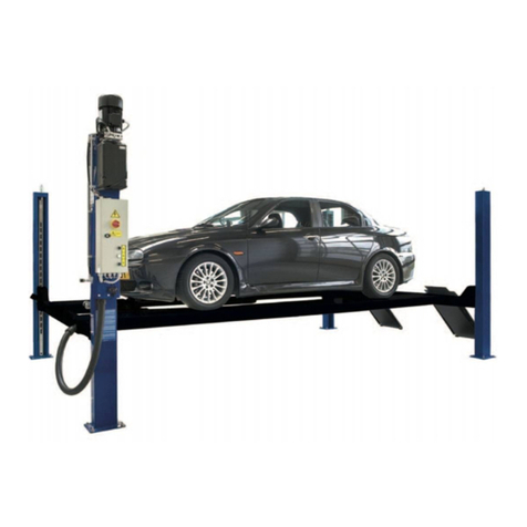
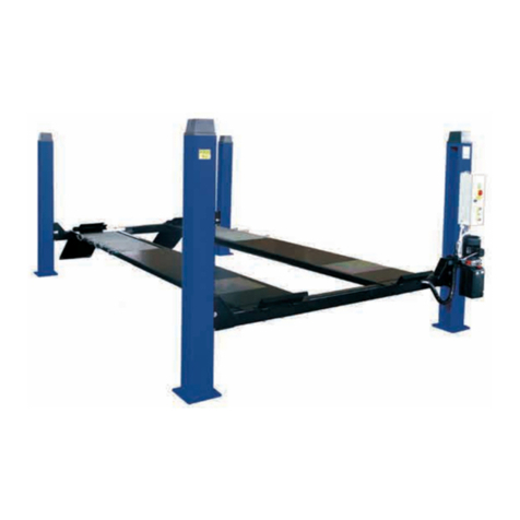
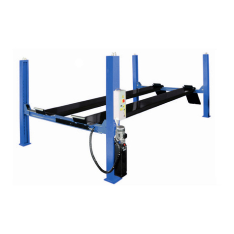
SOLLEVATORE A 4
COLONNE
GB
4-POST LIFT
526
Manuale di istruzioniperl’usoelamanuten-
zione dei
SOLLEVATORE ELETTROIDRAULICO
PER VEICOLI
Modello 526
Matricola N°
Anno di costruzione
COSTRUTTORE:
OMA S.p.A.
Sede centrale: Via dell’Artigianato,64
36045 LONIGO (VI) -ITALY
Telefono ++ / +444 / 436199
Telefax ++ / +444 / 436208
1° Emissione-01Marzo1996
CENTRODIASSISTENZAAUTORIZZATO:
Rev.7 ...............07/11/2003
Instructionmanualforusingandmaintaining
ELECTRO-HYDRAULIC LIFTS FOR VEHICLES
Model 526
Serial No.
Year of manufacture
MANUFACTURER:
OMA S.p.A.
Head Office:Viadell’Artigianato,64
36045 LONIGO (VI) -ITALY
Telefono ++ / +444 / 436199
Telefax ++ / +444 / 436208
1rd Edition - 01th March 1996
AUTHORIZEDSERVICE CENTRE:
Indice
Imballaggio, trasporto
e stoccaggio Pag. 3
Introduzione Pag. 4
Cap.1 Descrizione della
macchina Pag. 6
Cap.2 Specifiche tecniche Pag. 9
Cap.3 Sicurezza Pag.15
Cap.4 Installazione Pag.22
Cap.5 Funzionamento ed uso Pag.32
Cap.6 Manutenzione Pag.33
Cap.7 Inconvenienti e rimedi Pag.36
Appendice A Informazioni
particolari Pag.37
Appendice B Parti di ricambio Pag.38
Contents
Packing, transport and storage Page 3
Introduction Page 4
Chapter 1 Description of the
machine Page 6
Chapter 2 Specifications Page 9
Chapter 3 Safety Page 15
Chapter 4 Installation Page 22
Chapter 5 Operating
principles and usePage 32
Chapter 6 Maintenance Page 33
Chapter 7 Troubleshooting Page 36
Appendix A Special notes Page 37
Appendix B Spare parts Page 38
2
IMBALLAGGIO, TRASPORTO E
STOCCAGGIO.
LEOPERAZIONIDIIMBALLAGGIO,SOLLEVA-
MENTO,MOVIMENTAZIONE,TRASPORTO E DI
-
SIMBALLO DEVONOESSERE AFFIDATE ESCLU
-
SIVAMENTEAPERSONALECHESIAESPERTO
INTALIOPERAZIONIECHECONOSCABENEIL
PONTESOLLEVATORE ED IL PRESENTEMA-
NUALE
IMBALLAGGIO
Ilpontesollevatorevienespeditosmontatoneiseguentipezzi:
Peso di un pez zo (Kg)
4colonne 44
2traverse 95
2rampedisalita 25
2fermaruote 2,6
2pedane: latocomando 325
latoopposto 240
1assiemecentralina 30
kitsalvapiedi 10
Ilpontesollevatorevienespeditoavvoltoinununicopaccoconfe-
zionatoconunalastradimaterialetermoretraibileesigillatocon
duereggemetalliche(Fig.1).
Ilpeso mediodel paccoè dicirca 1050Kg.
SOLLEVAMENTO E MOVIMENTAZIONE
Ipacchipossonoessere sollevatiespostatisoltantoconcarrelli
elevatori,mantenendounadistanzadialmeno90cmtraidue
braccidellaforca(Fig.1).
Sollevareunsolopaccopervolta.
Imezzisceltidevonoessereidoneialsollevamentoespostamento
insicurezza,tenendocontodidimensioni,peso,baricentrodel
pacco,sporgenze,partidelicatedanondanneggiare.
Fig.1 Imballoespostamento
Fig.1 Packingandmoving
NonsollevareospostareMAIilsollevatoremediantefascieo
imbracatureperilsollevamento(Fig.2).
STOCCAGGIO
Gliimballidevonosempreessereconservatiinluoghicopertiepro-
tettiatemperaturecompresefra-10°Ce+40°C.enondevono
essereespostiairaggidirettidelsole.
IMPILAMENTO DEI PACCHI
E’sempresconsigliatoinquantoilpaccononèprevistoperl’impi-
lamento.Labasestretta,ilpesonotevoleelaconsistenzadell’im-
ballorendonoproblematicoedelicatol’impilamento.
Qualorasirendessenecessariol’impilamento,occorreadottare
molteprecauzionieinparticolare:
-nonsuperaremaiiduemetridialtezzadellapila;
- non fare mai pile di pac chi sin go li, ma fare sem pre pile di pac chi a
coppieincrociatetraloro,inmododaottenerecatasteconuna
basepiùlargaedunacertastabilità;quindiprovvederearendere
sicurolostoccaggio,utilizzandoregge,legaccioaltrimezziidonei.
Neicassonideicamion,neicontainer,neivagoniferroviarisi
possonoimpilarealmassimoduepacchi,purchèvengano
reggiatitraloroeassicuraticontrolacaduta.
PACKING, TRANSPORT AND
STORAGE.
PACKING,LIFTING,HANDLING,TRANSPORTING
AND UNPAC KING OPE RA TIONS MUST BE PER-
FORMEDONLYBYEXPERIENCEDPERSONNEL
WITHAPPROPRIATEKNOWLEDGEOF THE LIFT
ANDAFTERREADINGTHISMANUAL
PACKING
Theliftisshippeddisassembledinthefollowingunits:
Unit weight (kg)
4posts 44
2crossbeams 95
2vehicleramps 25
2wheel stops 2,6
2platform: controlside 325
oppositeside 240
1hydraulicpowerunit 30
footprotectionkit 10
The lift is ship ped in a sing le pack en clo sed by a sheet of heat
shrinkmaterialandrestrai nedbytwosteelstraps(fig.1).
The avera ge weight of the pack is 1050 kg.
LIFTING AND HANDLING
The packs can belif ted andtranspor ted onlyusinglift trucks,
and kee ping the fork arm cen tres at least 90 cm apart (Fig.1).
Lift only one pack at a time.
Theliftingequipmentmustbecapableofliftingandmo vingthe
packsincompletesafety,bearinginmindthedimensions,weight
andcentreofgravityofthepack,anyprotrudingparts,anddelicate
partstoprotectfromimpactdamageetc..
Fig.2
Fig.2
NEVERattempttohoistortransport theunitusinglifting
slings (Fig.2).
STORAGE
The packs must be kept in a co ve red and pro tected area in a tem
-
peratu rerangeof -10°Cto+40°C.They mustnotbeex posedtodi-
rectsunlight.
STACKING THE PACKS
Weadviseagainststackingbecausethepacksarenotdesigned
forthistypeofstorage. Thenarrowbase,heavyweightandlarge
sizeofthepacksmakestackingdifficultandpotentiallydangerous.
Ifstackingisunavoidable,useallappropriateprecautions:
- ne ver stack to more than 2 me tres in height;
- ne ver make stacks of sing le packs, al ways stack pairs of packs in
a cross pat tern so that the base is big ger and the re sul ting stack is
morestable; once thestackiscomple te,restrainitusing straps, ro -
pesorothersuitablemethods.
Ama xi mumof two packscanbe stac kedonlor ri es,incon tai-
ners, and in rail way wa gons, on the con di tion that the packs
arestrappedtogetherandrestrainedtostopthemfalling.
3
APERTURADEGLIIMBALLI
All’arrivoverificarechelamacchinanonabbiasubitodannidurante
iltrasportoechecisianotuttiipezziindicatinellalistadispedizio
-
ne.
Ipacchidevonoessereapertiadottandotutteleprecauzioniper
evitaredanniallepersone(tenersiadistanzadisicurezzamentre
siapronoleregge)edanniaipezzidellamacchina(evitarecadute
dipezzidalpaccodurantel’apertura).
Énecessarioprestareparticolareattenzionepernondanneg-
giarelacentralinaoleodinamica,ilquadrocomandoeilcilin-
dromontatosullapedana.
ELIMINAZIONE DELL’IMBALLO
Iltermoretraibiledeveesseresmaltitocomerifiuto,secondolanor-
mativavigenteperilriciclodeimaterialiplasticinelpaesediinstal-
lazionedelpontesollevatore.
INTRODUZIONE
IATTENZIONE
Questomanualeèstatoscrittoperilpersonalediofficinaad-
dettoall’usodelsollevatore(operatore)eperiltecnicoaddet-
toallamanutenzioneordinaria(manutentore)pertanto,prima
dieffettuarequalsiasioperazionesulsollevatoree/osulsuo
imballaggio,occorreleggereattentamentetuttoilmanuale,
poichèessocontieneinformazioniimportantiper:
-LASICUREZZADELLEPERSONEaddetteall’usoedallama
-
nutenzioneordinaria,
-LASICUREZZADELSOLLEVATORE,
-LASICUREZZADEIVEICOLIsollevati.
CONSERVAZIONE DEL MANUALE
Ilmanualeèparteintegrantedelsollevatoreedevesempreac
-
compagnarlo,ancheincasodivendita.
Essodevesempreessereconservatoinvicinanzadelpontesolle-
vatore,inluogofacilmenteaccessibile.
L’operatoreedilmanutentoredevonopoterloreperireeconsultare
rapidamenteinqualsiasimomento.
SIRACCOMANDA,INPARTICOLARE,UNALETTURAATTENTA
ERIPETUTADELCAPITOLO3,CHECONTIENEIMPORTANTI
INFORMAZIONIEAVVISIRELATIVIALLASICUREZZA.
Ipontisollevatorisonostatiprogettatiecostruitirispettandoquanto
segue:
LEGGI:
Direttiveeuropee:73/23CEE,89/336CEE,98/37/CE
NORME TECNICHE:
Norme europee: UNIEN1493
IMPIANTO ELETTRICO:
Norme europee: UNIEN60204-1
OPENING THE PACKS
Whentheliftisdelive redmakesurethatithasnotbeendamaged
duringtransportationandthatallthepartsspecifiedonthepacking
listareeffectivelypresent.
Packsmustbeopenedadoptingalltheprecautionsrequiredto
avoidin ju rytoper sons(keepata safedistance whencutting the
straps)or da mageto partsofthema chine(beca refulthatno parts
aredroppedwhileyouareopeningthepacking).
Take spe cial care with the hydrau lic power unit, the con trol
panelandtheplatformcylinder.
DISPOSAL OF PACKING MATERIAL
Theheat shrink plasticshee tingmustbedi sposedofas wastema-
te rial in con for mity with the laws for recycling of pla stics in the
countryofinstallationofthelift.
INTRODUCTION
IWARNING
Thismanualhasbeenpreparedforworkshoppersonnelex-
pertintheuseof thelift(operator)andtechni cians responsib-
leforroutinemaintenance(maintenancefitter);readthema
-
nualbeforecarryingoutanyoperationwiththeliftand/or the
packaging.Thismanualcontainsimportantinformationregar-
ding:
-THEPERSONALSAFETYofoperatorsandmaintenancewor
-
kers,
-LIFTSAFETY,
-THESAFETYOFLIFTEDVEHICLES
KEEPING THE MANUAL
The ma nual is an in te gral part of the lift , and must be al ways
kept with it , even in the case of sale of the unit.
Themanualmustbekeptnext tothelift,inaneasilyaccessible
place.
Theoperatorandmaintenancestaffmustbeabletolocateand
con sult the ma nual quic kly and at any time.
ATTENTIVEANDREPEATEDREADINGOF CHAPTER3,
WHICHCONTAINSIMPORTANTSAFETYINFORMATIONAND
WARNINGS,ISPARTICULARLYRECOMMENDED.
Liftsarede signedandbuilt incompliancewith:
LAWS:
Europeandirectives:73/23CEE,89/336CEE,98/37/CE
TECHNICAL STANDARDS:
Europeanstandards:UNIEN1493
ELECTRICAL SYSTEM:
Europeanstandards:UNIEN60204-1
4
Ilsollevamento,iltrasporto,ildisimballo,ilmontaggio,l’installazio-
neelamessainservizio,lataraturaeleregistrazioniiniziali,la
manutenzioneSTRAORDINARIA,lariparazione,larevisione,lo
spostamentoelosmantellamentodelsollevatoredevonoessere
eseguitidaitecnicispecializzatideiRIVENDITORIAUTORIZZATI
odeiCENTRIASSISTENZAAUTORIZZATIdalCostruttore(vede-
recentroassistenzaautorizzatoindicatonelfrontespizio):
Ilcostruttorenonrispondedialcundannoapersone,veicoli
odoggetticausatidagliinterventisopracitatiseeffettuatida
personalenonautorizzatoodaunusoimproprioononcon-
sentitodelpontesollevatore
Pertuttequesteattivitàvengonoindicati,nelpresentemanuale,
soltantogliaspetti(operativiedisicurezza)chepossonoessere
utiliancheall’operatoreedalmanutentorepercomprenderemeglio
lastrutturaedilfunzionamentodelsollevatoreeperunsuomiglio-
reutilizzo.
Percomprendereillinguaggioadottatonelpresentemanuale,l’o-
peratoredevepossedereesperienzaspecificanelleattivitàdioffici-
na,diassistenza,manutenzioneeriparazionedeiveicolinonchèla
capacitàdiinterpretarecorrettamenteidisegnieledescrizioniri-
portatenelmanualeelaconoscenzadellenormeantinfortunistiche
generaliespecifichevigentinelpaeseincuivieneinstallatoilsolle-
vatore.
Glistessicriterivalgonoperlasceltadeltecnicomanutentoreche
dovrà,inoltre,possedereleconoscenzetecnichespecificheespe-
cialistiche(meccaniche,elettriche)necessariepereffettuareinsi-
curezzagliinterventiprevistinelmanuale.
Neltestodelmanualetroveretespessolediciture“operatore”e
“manutentore”ilcuisignificatoèilseguente:
OPERATORE:personaaddettaall’usodelsollevatore.
MANUTENTORE:personaaddettaallamanutenzioneordinariadel
sollevatore.
Lifting,transport,unpacking,assembly,installationandcommissio-
ning,adjustmentandinitialset-ups,NON-ROUTINEmaintenance,
overhauling, movingand takingdownof theliftmust alwaysbe
performedbyqualifiedpersonnelfromAUTHORISEDDEALERS
orLICENSEDSERVICECENTRES(contactyourlicensedservice
centreindicatedonthetitlepageofthismanual):
Themanufacturerwillnotbeheldliableforpersonalinjuryor
damagetovehiclesorpropertycausedbyimproperand/or
unauthoriseduseofthelift.
Inrespectofalltheabovementionedactivities,thismanualcovers
onlysuchoperationalandsafetyaspectsthatareconsidereduse-
fulforoperatorsandmaintenancepersonneltogainamorecom-
pleteunderstandingofthestructureandfunctionsoftheliftsothat
it can be used in the best way.
Toensureadequatecomprehensionofthetechnicallanguagein
thismanualtheoperatormusthavespecificexperienceofwork-
shopproceduresforservicing,maintenanceandrepairofvehicles
andmust alsobe capab leofin terpre tingthe drawings anddescrip
-
tionsinthemanualandbeawareofgeneralandspecificaccident
preventionregulationsinforceinthecountryofinstallation.
Thesameconsiderationsapplytothemaintenancefitterwhomust
alsopossessspecifictechnical(mechanicalandelectrical)skills
necessarytoperformthevariousinterventionsdescribedinthe
manualinconditionsoftotalsafety.
Thewords“operator”and“maintenancefitter”areusedwiththefol -
lowingmeaninginthemanual:
OPERATOR: personinchar geofusingthelift.
MANUTENANCEFITTER:personinchargeofroutinemaintenan-
ce of the lift.
5
CAP.1. DESCRIZIONE DELLA
MACCHINA
Ipontisollevatoria4colonnesonofissi,cioèancoratialsuolo;
sonoprogettatiecostruitiperilsollevamentoelostazionamentoin
quotadiautoveicoliefurgoni.
Sonocompostiprincipalmentedaunapartefissa,ancorataalter-
reno(colonne)edaunapartemobile(traverseepedanedisoste-
gnoesollevamento).
Ilfunzionamentoèditipoelettroidraulico.
Questisollevatorisonocomposti,fondamentalmentedaquattro
parti:
-gruppostrutturafissa;
-gruppostrutturamobile;
-gruppodisollevamento;
-sicurezze.
Infigura3sonoindicatelevariepartichecompongonoilsollevato-
reelezonedilavoroattornoalsollevatorestesso.
Latooperatore:èillatoanterioredelsollevatore,quellochecom-
prendeanchelazonariservataall’operatoreincuisiaccedeal
quadrocomandiedèoppostaallatodiingressodelsollevatore.
Latoposteriore:èillatooppostoaquellooperatoreincuisitrova-
nolerampediaccessoalsollevatore.
Latidestroesinistro:sonostabilitirispettoall’operatorerivoltover
-
soilsollevatore.
Zonadisicu rezza:èlazonadi sicurezzaincuinon sidevemaiso-
starequandoilsollevatoreèinfunzione;spiegazionimaggiormen-
tedettagliateletroveretenelcapitolo3“Sicurezze”.
Lanumerazioneinfigura3siriferiscea:
1colonnalatocomando(siintendeper
convenzioneinternacomeanterioredestra)
2 colonnaanterioresinistra
3colonnaposterioresinistra
4colonnaposterioredestra
5traversalatocomando(traversaanteriore)
6traversatraversaposteriore
7pedanadestra,fissa
8pedanasinistra,mobile
Figura3
Figure3
CHAPTER 1. DESCRIPTION
OF THE MACHINE
Four-postliftsarefixedinstallations,i.e.anchoredtothefloor;the
unitsaredesignedandbuilt forliftingcarsandvansandholding
theminanelevatedposition.
Theunitsareessentiallymadeupofafixedpartthatisanchored
tothefloor(posts)andamovingpart(cross-piecesandplatforms).
Theoperationiselectro-hydraulic
The re are four ba sic parts of the lifts:
-fixedstructureassembly;
-movablestructureassembly;
-liftingassembly;
-safetydevices.
Figu re3shows thevarious partsofthe liftandthe operating zones
inthesurroundingarea.
Opera torside:this isthefront ofthelift, inclu ding thearea reser
-
ved for the ope ra tor with the con trol pa nel. The ope ra tor side is op
-
positethevehicleaccessside.
Rear side: it is the side op po sed the ope ra tor’s one, with the lift ac-
cess ramps.
Rightandleftsides:theright andleftisconsideredfromtheopera
-
tor’s standpoint when facing the lift.
Sa fe ty zone: an area that must be kept clear of per sons when the
liftisinuse;referto“Safetydevices”chapter3fordetails.
Keytofigure3:
1controlsidepost(conventionallythefrontright-handpost)
2 front left post
3rear left post
4rear right post
5controlsidecross-piece(frontcross-piece)
6rearcross-piece
7rightfixedplatform
8leftmovingplatform
6
1
5
7
8
4
3
6
2
Zonaoperatore
Bedienungszone
GRUPPO STRUTTURA FISSA
E’ costituita da quattro colonne verticali in lamiera di acciaio
piegata alla cui base è saldata una piastra forata che permette
il fissaggio al suolo mediante tasselli ad espansione (vedere
capitolo 4 “ installazione”).
All’internodiognicolonnasonoalloggiati:
-un’astadisicurezzaconasole(1)perl’appoggiodeimartellettidi
sicurezza,
-unafuneinacciaioperilsollevamento(2),
-unaguidaperloscorrimentoverticaledelletraverse.
Fig.4 Colonna
Fig.4 Post
Sullasommitàdiognicolonnasonoancorate:
-l’estremitàdell’astadisicurezza(4),(fissatacondadoecontroda-
doM20,classediresistenza8.8);
-l’estremitàdellafuneinacciaio(5),chehauncodulofilettatoM20
(fissatocondadoecontrodadoM20,classediresistenza6S).
Lalunghezzadelcodulofilettatoconsentelaperfettaregistrazione
dellefuni,olaripresadiunloroeventualeallungamento.
Allacolonnacomando(Fig.6)sonofissatiilquadroelettricodico-
mandoelacentralinaidraulica.
Sulpannellodelquadroelettricodi
comandosonoinstallati:
-l’interruttoregenerale(1),
-ilpulsantedisalita(2),
-ilpulsantedidiscesa(3);
-sulpannellodelquadroelettricosi
trovaancheilpulsantedistaziona-
mento(4).
Lacentralinaidraulicaècomposta
da:
-unmotoreelettricodicomando(5),
-unapompaidraulicaadingranaggi
(6),
-un’elettrovalvoladidiscesa(7),
-una vitedimes sain scarico ma
-
nualedelponte(12),
-unavalvoladimassimapressione
(8),
-un serbatoio olio(9),
-untuboflessibiledimandataolio
(10),
-untuboflessibileperilrecupero
dell’olio(11)
NOTA:
Il tubo di man da ta olio (10) può tro-
varsiinpressione.
Iltubodirecupero olio(11)nonè
maiinpressione.
Fig.6 Pannellodicomandoecentrali
-
naidraulica.
FIXED STRUCTURE ASSEMBLY
Thestructureincludesthefourverticalpostsinbentsteelplate
withapre-drilledbaseplateforexpansionanchorstosecurethe
unittothefloor(seechapter4“Installation”).
Eachposthouses:
-asafetyrodwithslots(1)toengagethesafetywedges,
- a steel cab le for lif ting (2),
-aguideforthecross-pieceverticalsliding(3).
Fig.5 Sommitàcolonne
Fig.5 Post top
Thefol lowingparts arean chored tothe top ofeach post:
-endofsafetyrod (4),(securedwithM20nutandlocknut,class
8.8);
- the end of the steel cab le (5), which is fit ted with an M20 threa-
ded shank (fixed with M20 nut and lock nut, class 6S).
The length of the cables can be per fectly adju sted - also to take up
slack due to stretching, thanks to the length of the threa ded shanks
on the ends of the cables.
Thedrive post(Fig.6)mounts theelectri calcontrol pa nelandthe
hydraulicpowerunit.
Thefollowingcomponentsarepre-
senton thecontrol panel:
- main switch (1),
-LIFT button (2),
-LOWERINGbutton(3);
-thecontrolpanelalso mountsa
stopbutton(4).
Thehydraulicpowerunitcomprises:
-motor(5),
- hydrau lic gear pump (6),
-loweringsolenoidvalve(7),
-the cablemicro switch(4)
-ma nuallowering screw (12),
-reliefvalve(8),
-oilreservoir(9),
-oildeliveryhose(10),
- oil drain hose (11)
NOTE:
Thedeliveryhose(10)issometimes
pressurised;
thedrainhose(11)isneverpressuri-
sed.
Fig.6 Controlpanelandhydraulic
power unit.
7
1
4
2
5
8
6
9
3
7
10
11
12
1
2
3
4
5
GRUPPO STRUTTURA MOBILE
Écostituito da due traverse e da due pedane.
Ognitraversascorreverticalmentetraduecolonne.
Comesi vedein fig.7,alle dueestre mità diognitra versa sonofis-
sati:
-lepuleggedirinvio(1)dellafunedisollevamento,
-gliinnestimeccanicidisicurezza(martelletti)(2e3).
Ilmartellettodistazionamento(pos.3)siinserisceautomaticamen-
tedurantetuttalafasedisalitaenellostazionamento.Deveesse-
redisinseritoelettricamente durantelafasedidiscesa.
Incasodirotturadellafune,siazio-nailmicrointerruttorefuni(4)
cheprovocailbloccodellaparteelettricadelponteel’inserimento
delmartellettodistazionamento,pertantodellasuapartemobile
nonchèdelcarico.
Leduepedaneportaveicoli(Fig.9)appoggianosulletraverse.
Lapedanasinistra(1)èfissa,mentrelapedanadestra(2)èmobi-
leepuòscorrereorizzontalmenteperadattarsiallediversecarreg
-
giatedeiveicoli.Entrambesonodotatedibordiinterni(3)diconte
-
nimentodeipneumaticidelveicoloediarrestifissidisicurezza(4)
cheimpedisconoalveicolostessodioltrepassareaccidentalmente
lafinedellapedana;lerampediaccesso(5),incernieratesullepe-
dane,siposizionanoverticalmentequandolepedanesalgono,
bloccandoinmanieradefinitivailveicolo.
Fig.9 PedaneeTraverse
All’internodellapedanalatoco-
mando (Fig.10),conac cessodal
sololatoinferiore(latosuolo),
sitrovano:
-ilcilindroidraulicodisollevamento
(1);
-lavalvolaparacaduteodiblocco
(2);
-ilgio godiattacco (3)dellefuni di
acciaio;
-duegruppipuleggedirinvio(4)
dellefuni.
Fig.10-
Internopedanafissa
MOVABLE STRUCTURE
Themovablestructureconsistoftwocross-piecesandtwoplat
-
forms.
Eachcross-piecetranslatesverticallybetweentwoposts.
Asshown infig.7, theends ofthe cross-pi eces arefit tedwith the
followingparts:
- re turn pul leys (1) for the lift cab le,
-mechanicalsafetydevices(wedges)(2and3).
Thewedge(pos.3)willengageautomaticallyduringliftingand
when the lift is rai sed.
In case of breakage of the cab le, the cab le mi cro switch (4) cau ses
thelockoftheliftelectricalpartandtheengagementofthesafety
wedge,thereforeitstopsthemovablepartandtherelevantvehic-
le.
Thetwoplatforms(Fig.9)aresupportedonthecross-pieces.
The left plat form (1) has no adjustment; the right plat form (2) is free
to sli de across the width of the lif ting area to adapt to the track
widthof thevehicle beinglifted.
Bothplatforms have insidekerbs(3) tokeepthevehiclety resfully
onthe lifting surfa ce,and fixedwheel stops(4) tostop thevehic le
from going beyond the ends of the plat forms;
Theaccessramps(5),pivotedtotheplatforms,automaticallyre
-
achaverticalpositionwhentheplatformslift,therebysecuringthe
vehic le also from the ac cess end.
Fig.9 Platformsandcross-pieces
Thefollowingcomponentsareloca-
ted be neath the fixed plat form (Fig.
10),andareaccessibleonlyfrom
underneath:
-hydraulicliftcylinder(1);
-parachutesafetyvalve(2);
-cleviscoupling(3)for thesteel
cables;
-twocablereturnpulleyassem-
blies (4).
FiIg.10
Interiorofthefixedplatform
8
Fig.8 4
1
3
Fig.7 4
1
3
1
3
2
3
2
3
1
4
4
CAP.2. SPECIFICHE TECNICHE
PORTATA: ................................................4000 kg (39240 N)
Alt.max.sollevamentoauto......................1750 mm
Alt.min.supportisollevamento .................190mm
Interasselongitudinalecolonne .................4800 mm
Interassetrasversalecolonne...................3030 mm
Larghezzaliberatracolonne.....................2850 mm
Larghezzapedane.....................................625mm
Lunghezzapedane....................................5000 mm
Tempodisalita..........................................50 sec
Tempodidiscesa ......................................45 sec.
FUNEdisollevamentoinacciaio,conleseguenticaratteristiche:
Diametro....................................................11 mm
Numerodifili .............................................227
Resistenzadeifili ......................................1960 N
Diametroprimitivopulegge........................220mm
Rumorosità ................................................70dB(A)/1m
PESOtotaledelsollevatore .....................circa1030Kg
Temperaturadifunzionamento .................-10°C / + 50°C
Ambiente di lavoro: locale chiuso.
Fig.11-Dimensioniedingombri
MOTORE ELETTRICO
Tipo ...........................................................C90
Potenza.....................................................2.2 KW
Tensione....................................................230- 400V trif. +/-5%
Frequenza .................................................50 Hz
N° poli........................................................4
Velocità......................................................1400 giri/1’
Formacostruttiva.......................................B 14
Classeisolamento.....................................F
Assorbimento ............................................230V: 11A
..................................................................400V: 6,4A
Il collegamento del motore deve essere eseguito riferendosi
agli schemi elettrici allegati.Il senso di rotazione del motore è
sinistro (antiorario) come indicato nella targhetta applicata sul
motore stesso.
POMPA
Tipo ...........................................................18
Modello......................................................10A5X348N
Cilindrata...................................................5 cm3 /g
Trasmissione:tipodigiunto.......................TR04
Pressionedilavorocontinuativa ................210bar
Pressionedilavorointermittente ...............230bar
Pressionedipicco .....................................250bar
CHAPTER 2 SPECIFICATIONS
CAPACITY:...............................................4000 kg (39240 N)
Max.vehicleliftingheight..........................1750 mm
Min.groundclearanceofliftstructure.......190 mm
LongitudinalC/Cdistancebetweenposts .4800 mm
TransverseC/Cdistancebetweenposts...3030 mm
Effectiveclearancebetweenposts............2850 mm
Platformwidth............................................625mm
Platformlength..........................................5000 mm
Lift time......................................................50 sec
Loweringtime ............................................45 sec
LIFTINGCABLESinsteel,havingthefollowingfeatures:
Diameter....................................................11 mm
Strands......................................................227
Tensilestrengthofstrand..........................1960 N
Pulleypitchdiameter.................................220 mm
Noise.........................................................70dB(A)/1m
OVERALL WEIGHT of lift unit...................1030kgapprox.
Workingtemperaturerange.......................-10°C / + 50°C
Installation requirements: enclosed area.
Fig.11-Overalldimensionsandclearances
MOTOR
Type ..........................................................C90
Power ........................................................2.2 kW
Voltage......................................................230-400Vth.-ph.+/-5%
Frequency .................................................50 Hz
Poles.........................................................4
Speed ........................................................1400 rpm
Buildingshape...........................................B 14
Insulationclass..........................................F
Absorption.................................................230V: 11A
..................................................................400V: 6.4A
When connecting the motor refer to the enclosed wiring
diagrams.
The motor has left-handed rotation (counter-clockwise) as
shown on the data plate on the casing.
PUMP
Type ...................................................................18
Model ..................................................................10A5X348N
Displacement ......................................................5 cc/rev.
Trasmission:tipodigiunto.................................. TR04
Continuousworkingpressure .............................210 bar
Intermittentworkingpressure..............................230 bar
Peakpressure.....................................................250 bar
9
CENTRALINA OLEODINAMICA
Possonoveniremontate,indipendentementedalmodellodelpon
-
te,duediversecentralineoleodinamiche,ovveroleparti,compo-
nentilapompa,chetraduconoilmovimentodelmotoreinspinta
dell’olio nei tubi. In fi gu ra 12 è mo stra to il tipo K3 (OIL SISTEM).
Fig.12- Centraline
OLIO
Ilserbatoiodell’oliocontieneolioidraulicoabasemineralesecon-
donormativaISO/DIN6743/4congradodicontaminazionenon
superioreallaclasse18/15secondonormativaISO4406comeIP
HYDROOIL32;SHELLTELLUST37oequivalenti.
HYDRAU LIC POWER UNIT
Irrespectiveofthemodel,theliftcanbesuppliedwithanoptionof
twodifferenthydraulicpowerunits,i.e.thevariouscomponentsof
thepumpthat con verttherotary mo tionofthemotor into fluidpres-
sureforthehydrauliccircuit.
Fi gu re 12 shows the type K3 (OIL SISTEM).
Fig.12-Hydrau licpowerunits
OIL
ThehydraulicoilreservoirisfilledwithmineraloiltoISO/DIN
6743/4,contaminationcategorynohigherthanclass18/15accor-
ding to ISO 4406, such as IP HYDRO OIL 32; SHELL TEL LUS T
37oranequivalentoil.
10
1Valvoladiritegno Checkvalve
2Elettrovalvola Solenoidvalve
3Scaricomanuale Manualoutlet
4Caricoolio Delivery
5Tuboperrecuperoolio Drainhose
6Valvolaregolatricediscarico Outletadjustingvalve
7Valvolamassimapressione Reliefvalve
SCHEMI ELETTRICI ED OLEODINAMICI WIRING DIAGRAMS AND HYDRAULIC
11
Rif.
Ref. Descrizione Description Marca
Brand Art.
Article Qt.à
Q.ty
C1-C2 C1-C2 Elettromagnete Electromagnet WARNER TT10 24VAC 50Hz 2
ETV C3 Elettrovalvola Solenoidvalve OIL SISTEM 24VAC 50/60Hz ED100% 1
F1 FU1-FU4 Porafusibile Fuse carrier WEBER PCH10x38+CH10x38 3
F3 PTC Limitatoreditemperatura Thermallimiter Integratonelmotore/Integrateinthemotor 1
FC5 QM5 Microiterruttoresalita Liftmicroswitch PIZZATO FR654 1
IG QS Interruttoregenerale Masterswitch SPRECHER LA2-12-1754+LFS2-N-6-175+LA2-12
-C4+LA2-G2853+LA2-G3194 1
K1 KM1 Teleruttore Contactor TELEMECANIQUE LC1K0910B7 24V 50/60Hz 1
K2 KA2 Teleruttorediscesa Descentcontactor TELEMECANIQUE LC1D12+LA1DN11 1
M M Motoreelettrico Electricmotor 230/400V 50Hz 1
SB1 SB1 Pulsantesalita Upbutton TELEMECANIQUE HB7EA21P (1NO) 1
P2 SB2 Pulsantediscesa Downbutton TELEMECANIQUE HB7EA21P (1NO) 1
P3 SB3 Pulsantestazionamento Stoppingbutton TELEMECANIQUE ZB5AA8+ZB5AZ009+ZBE101 (1NO) 1
QM1 FR2 Interruttoremagnetico Magneticswitch 20A TYPE C 1
S1 - S4 QM1/QM4 Microiterruttorefune Cablemicroswitch PIZZATO FR1454 4
TR TM Trasformatore Transformer C.E. 230-400/24V300VA50/60Hz 1
Morsettilinea Line clamps CABUR CBD2 2.5mmq 4
Morsettiterra Earth clamps CABUR TE4/D-TE4/0 4mmq 1
SCHEMA TOPOGRAFICO TOPOGRAPHICDIAGRAM
12
Elettromagnete
Electromagnet
Quadroelettrico
Controlpanel
Microfuni
Cablemicro-switch Microfuni
Cablemicro-switch
Microfuni
Cablemicro-switch
Microfuni
Cablemicro-switch
Elettromagnete
Electromagnet
SCHEMA OLEODINAMICO
Rif. Descrizione
1Valvolaparacadute
2Elettrovalvola
3Valvoladiritegno
4Valvoladimassima
5Valvoladistrozzamento
6Motore
7Pompa
8Filtro
9Serbatoio
HYDRAULIC CIRCUIT DIAGRAM
Re. Description
1Parachutevalve
2Solenoidvalve
3Checkvalve
4Reliefvalve
5Throttlevalve
6Motor
7Pump
8Filter
9Reservoir
TIPI DI VEICOLI SOLLEVABILI E INGOMBRI 13
1
4
7
2
53
6
8
9
2
Motore+protezionetermicamotore-Motorandthermalswitch(8-9)
Finecorsa -Limitswitch(3-4)
Elettrovalvola-Solenoidvalve(0-7)
Elettromagneti-Electromagnet(0-5)(0-6)
Microinterruttori fune and ON/OFF switch for bro ken or slac ken rope (1-02) (1-2)
Ipontisollevatorisiadattanopraticamenteatuttiiveicolidipeso
nonsuperiorea4000kgelecuidimensioninoneccedanoquelle
riportatediseguito.
DIMENSIONIMASSIMEDEIVEICOLIDASOLLEVARE
Lalarghezzanondeveeccederei2400mm.
Ilpas sotragli assinondeveec cedere i3000mm.
Ladistanzamassimatraibordiesternideipneumatici,compresoil
rigonfiamentoaterra,nondeveeccederei2000mm.
Ladistanzaminimatraibordiinternideipneumatici,compresoilri-
gonfiamentoaterra,nondeveessereinferiorea900mm.
L’altezzaminimadaterrapuòinterferireconlestrutturedelsolle
-
vatore.
Fareattenzionesoprattuttoalleautovetturesportive.
Eventualicarrozzatispecialipossonoesseresollevatitenendoperò
contodellaportatadelsollevatore.
Anchelazonadisicurezzaperlepersonedovràessereade-
guataalledimensionispecialidelveicolo.
Glischemiseguentiriportanoicriteriperdefinireilimitidiimpiego
delsollevatore.
Fig.13 Misureminimeemassime
PERINGOMBRIMAGGIORIVERIFICAREILCARICOMASSIMO
EDILSUOSBILANCIAMENTO
PESIMASSIMIDEIVEICOLIDASOLLEVARE
Fig.14 Ripartizionepesi“A”
Fig.14 Weightdistribution“A”
TYPES OF VEHICLES SUITABLE FOR BEING LIFTED AND
OVERALL DIMENSIONS
Liftsaresuitableforvirtuallyallvehicleswithtotalweightofno
morethan4000kgandwithdimensionsnotexceedingthebelow
data.
MAXIMUMDIMENSIONSOFVEHICLESMAINLIFTED
Max. width: 2400 mm.
Max.wheelbase:3000mm.
Max.distancebetweenouterwalloftyres,inclusiveofbulgecau-
sed by weight of vehic le on ground: 2000 mm.
Min.distancebetweeninnerwallsoftyres,inclusiveofbulgecau-
sed by weight of vehic le on ground: 900 mm.
Caution:thelowerpartsofthevehicleunderbodycouldinterfere
withstruc turalparts ofthelift.
Takeparti cularcarein thecasesports-cars.
Theliftwillalsohandlecustomisedornon-standardvehiclesprovi
-
dedtheyarewithinthemaximumspecifiedcarryingcapacity.
Alsothepersonnelsafetyzonemustbedefinedinrelationto
vehicleswithunusualdimensions.
Thefollowingdiagramsillustratecriteriausedtodefinetheopera-
tingli mitsof thelift.
Fig.13 Maximumandminimumdimensions
FORLARGERDIMENSIONSCHECKTHEMAXIMUMLOAD
ANDPOSSIBLEUNBALANCE
MAXIMUMWEIGHTSOFVEHICLESBEINGLIFTED
Fig.15 Ripartizionepesi“B”
Fig.15 Weightdistribution“B”
14
A
B
C
D
Min. (mm) Max. (mm)
A-3000
B100 -
C-2000
D1000 -
E-2400
E
CAP.3 SICUREZZA
Éestremamenteimportanteleggerequestocapitoloattenta-
menteedinognisuapartepoichècontieneimportantiinfor-
mazionisuirischicheoperatoreemanutentorepossonocor-
rereincasodiunusoerratodelpontesollevatore.
Neltestocheseguetroveretechiarespiegazionisualcunesi-
tuazionidirischioopericolochesipossonoverificaredurante
l’usoelamanutenzionedelsollevatore,suidispositividisicu
-
rezzaadottatiesullorousocorretto,suiri schiresiduie sui
comportamentidatenere(precauzionigeneraliespecifiche
pereliminarlioneutralizzarli).
IATTENZIONE:
Isollevatorsonostatiprogettatiecostruitiperil
sollevamentoelostazionamentoinquotadeivei-
coliin am bien te chiu so. Ogni al tro uso nonècon
-
sentitoedinparticolareessinonsonoidoneiper
operazioni di:
-lavaggioeverniciatura;
-ponteggioosollevamentodi persone;
-pressaperschiacciare;
-montacarichi;
-CRICpersollevareocambiareruote.
Ilcostruttorenon rispondedialcundannoaper-
sone,veicoliodoggetti causatidall’usoimpro-
prioononconsentitodeipontisollevatori
Éestremamenteimportantecheinfasedisalitaodiscesal’o-
peratoreagiscasoltantodallapostazionedicomandoindicata
inFig.16.
Évietatoachiunquesostaresottoletraversee/olepedaneinmo-
vimentoosostareentrolazonaarischioindicatainFig.16.
Infasedilavorolapresenzadipersonesottoilveicoloèammessa
soltantoquandoilveicoloègiàsollevato,letraverseelepedane
sonofermeelesicurezzemeccaniche(martelletti)sonoinserite
nelleasoledelleastedisicurezza.
NON UTILIZZARELAMACCHI NASENZALEPRO
-
TEZIONIOCONLEPROTEZIONIDISATTIVATE.
ILMANCATORISPETTODIQUESTENORME
PUO’RECAREGRAVIDANNIALLEPERSONE,AL
SOLLEVATOREEDAIVEICOLISOLLEVATI.
Fig.16
CHAPTER 3 SAFETY
Itisextremely im portanttoreadthischapterof the manualca-
refullyandfrombeginningtoendasitcontainsimportantin
-
formationregardingtheriskstheoperatorormaintenancefit
-
ter may be ex po sed to if the lift is used in cor rectly.
Inthefollowingtextthereareclearexplanationsregarding
certainsituations ofriskordangerthatmay ariseduringthe
operationormaintenanceofthelift,thesafetydevicesinstal
-
ledandthecor rect use of suchsystems,residualrisksand
operativeprocedurestouse(generalandspecificprecautions
toeliminatepotentialhazards).
IWARNING:
Lifts are de si gned and built to lift vehi cles and
holdthemintheelevatedpositioninanenclosed
work shop. All ot her uses of the lifts are unaut ho
-
rised.Inparticular,theliftsarenotsuitablefor:
- was hing and re spray work;
-creatingraisedplatforms for personnelorlifting
personnel;
- use as a press for crushing pur po ses;
- use as elevator;
-use as a lift jack for lif tingvehic le bo dies or
changingwheels.
Themanufactureris not liableforanyinjuryto
personsordamagetovehiclesandotherproper
-
tycausedbytheincorrectandunauthoriseduse
of the lifts.
Duringliftingandloweringmovementstheoperatormustre-
maininthecontrolstationasdefinedinfigure16.
Thepresenceofpersonsbeneaththecross-piecesand/ortheplat-
formswhentheyaremoving,orthepresenceofpersonsinsidethe
dangerzoneindicatedinfigure16isstrictlyprohibited.
Duringoperationspersonsareadmittedtotheareabeneaththe
vehicleonlywhenthevehicleisalreadyintheelevatedposition,
whenthecross-piecesandplatformsarestationary,andwhenthe
mechanicalsafetydevices(wedges)arefirmlyengagedintheslots
onthesafetyrods.
DONOTUSETHELIFTWITHOUTPROTECTION
DEVICESORWITHTHEPROTECTIONDEVICES
INHIBITED.
FAILURETOCOMPLYWITHTHESEREGULA-
TIONSCANCAUSESERIOUSINJURYTOPER
-
SONS,ANDIRREPARABLEDAMAGETOTHE
LIFTANDTHEVEHICLEBEINGLIFTED.
15
Zonadisicurezza
Safetyzone
Zonaoperatore
Operatorzone
PRECAUZIONI GENERALI
L’operatoreedilmanutentoresonotenutialrispettodelleprescri
-
zionicontenuteinleggienormeantinfortunistichevigentinelpaese
incuièinstallatoilsollevatore.
Devonoinoltre:
-operaresempredallepostazionidilavoroprevisteedindicatenel
manuale;
-nonrimuoverenèdisattivareicartereleprotezionimeccani-
che,elettriche,odialtranatu ra;
-prestareattenzioneagliavvisidisicurezzariportatinelletarghette
applicatesullamacchinaenelmanuale.
Neltestodelmanualegliavvisidisicurezzasarannoevidenziati
nelleformeseguenti:
PERICOLO:Indicaunpericoloimminentechepuòcausaredanno
allepersone(gravilesionioanchelamorte).
ATTENZIONE:Indicasituazionie/ocomportamentirischiosiche
possonocausaredanniallepersone(lesionipiùomenogravie/o
anchelamorte).
CAUTELA:Indicasituazionie/ocomportamentirischiosichepos-
sonocausaredannidiminoregravitàallepersonee/odannialsol-
levatore,alveicolooadaltrecose.
RISCHIODIFOLGORAZIONE:èunparticolareavvisodisicurezza
chevieneriportatosulsollevatore,tramitetarghetta,inalcunipunti
doveèparticolarmenteelevatoilrischiodifortiscosseelettriche.
RISCHI E PROTEZIONI
Vediamooraqualirischipossonocorrereglioperatorioilmanuten-
toreinfasedistazionamentodelveicolosullepedaneequalipro-
tezionisonostateadottatedalcostruttoreperridurrealminimotali
rischi:
SPOSTAMENTI LONGITUDINALI
Glispostamentilongitudinalisonoimovimentiinavantioall’indie
-
trodelcarico.
Comeprotezionesonostatiapplicatideifermifissi(1)sullatoante-
rioreedeifermibasculanti(2),integraticonlepedaneche,durante
lasalitaenellostazionamento,bloccanoilveicoloimpedendogli
ognimovimentopericoloso.
Fig.17 Spostamentolongitudinaleeprotezione
GENERAL PRECAUTIONS
Theoperatorandthemaintenancefitterarerequiredtoobserve
theprescriptionsofsafetyregulationinforceinthecountryofin-
stallationofthelift.
Furthermore,theoperatorandmaintenancefittermust:
-alwaysworkinthestationsspecifiedandillustratedinthisma
-
nual;
-neverremoveordeactivatetheguardsandmechanical,electri-
cal,orothertypesofsafetydevices;
-readthesafetynoticesplacedonthemachineandthesafetyin-
formationinthismanual.
Inthemanualallsafetynoticesareshownasfollows:
DANGER:indicatesimminentdangerthatcanresultinseriousin-
jurytopeopleordeath.
WARNING:indicatessituationsand/ortypesofmanoeuvresthat
areunsafeandcancausemoreorlessharmfulinjuriesordeath.
CAUTION:indicatessituationsand/ortypesofmanoeuvresthat
areunsafeandcancauseminorinjurytopersonsand/ordamage
thelift,thevehicleorotherproperty.
RISKOFELECTRICSHOCK:aspecificsafetynoticeplacedon
theliftin areas wheretheriskof electricshockisparti cularlyhigh.
RISKS AND PROTECTION DEVICES
Weshallnowexaminetherisksthatoperatorsormaintenancefit-
tersmay beex posed towhen thevehic leisstan dingon theplat-
formsintheraisedposition,togetherwiththevarioussafetyand
protectiondevicesadoptedbythemanufacturertoreduceallsuch
hazardstotheminimum:
LONGITUDINAL MOVEMENTS
Longitudinalmovementsrefertoforwardandbackwardmovement
ofthe load(vehic le).
Toprotectagainsttheconsequencesoflongitudinalmovement we
have in stal led fixed wheel stops (1) at the front of the lift, and pi vo-
ting stops (2) at the rear. The stops are in te gral with the plat forms
andservetosecurethevehicleduringliftingandloweringmove
-
mentsandwhenthevehicleisatastandstillintheraisedposition,
thuspreventinganypotentiallydangerousmovement.
Fig.17 Longitudinalmovementandsafety systems
16
1
2
SPOSTAMENTI LATERALI
Glispostamentilateralisonoimovimentiversodestraoversosini-
stracheilveicolopuòavere,specialmentedurantelafasedisalita
sulpontesollevatore.
Leprotezioniadottatecontrogli spostamentilateraliconsistonoin
bordaturerialzate(1)applicateatuttoilbordointernodellepedane
cheimpediscono,quandolepedanesonocorrettamenteposizio-
nate,movimentilateralialcarico.
Fig.18 Spostamentolateraleeprotezioni
Perunasicurezzaottimaledellepersoneedeimezzièimportante
che:
-sirispettilazonadisicurezzaduranteilsollevamento(vedere
Fig.16),
-ilmotoredelveicolosiaspento,lamarciainnestata,edilfrenoa
manotirato,
-ilveicolosiaposizionatoinmanieracorretta(vedereFig.19);
-venganosollevatisoltantoveicoliammessi,senzasuperaremai
laportata,gliingombriinaltezzaelesporgenze(lunghezzaelar-
ghezzadelveicolo);
-nonvisianopersonesullepedaneduranteilsollevamentoelo
stazionamento(Fig.19).
Fig.19 Veicolocaricatocorrettamente
SIDE MOVEMENTS
Sidemovementsrefertoshiftingofthevehicletowardtheleftor
rightofthelift,especiallyduringtheliftingcycle.
Thesafetydevicesinstalledtoprotectagainstthistypeofmove-
mentcompri se raisedkerbs(1)on theinneredgesof theplat-
forms,whicheffectivelystoplateralmovementoftheload-provi-
dedthe platformsarecor rectlyspaced.
Fig.18 Sidemo vementsandplatform kerbs
Foroptimalpersonalsafetyandsafetyofvehicles,observethefol-
lowingregulations:
-do not enterthe safetyzone whilevehicles arebeinglifted (see
Fig.16),
-switchofftheengineofthevehicle,engagea gearandengage
thehandbrake,
-makesurethevehicleispositionedcorrectly(seeFig.19);
-besuretoliftonlyapprovedvehicles,neverexceedthespecified
carryingcapacity,maximumheight,andprojections(vehiclelength
and width);
-make surethat there areno persons onthe platforms during up
anddownmovementsandduringstanding(Fig.19).
Fig.19 Correctlypositionedvehicle
17
1
RISCHI IN FASE DI SOLLEVAMENTO DEL VEICOLO
Controisovraccarichiinpesoecontroeventualirotturesonostati
adottatiiseguentidispositividisicurezza:
•Incasodiuncaricoeccessivosulsollevatoreintervienelaval-
voladimassimapressionesucentralina(Pos.1,Fig.20).
Fig.20 Valvoladimassima
Fig.20 Reliefvalve
•Incasodirotturadiunoopiùtubidell’impiantooleodinamicoin-
tervieneunavalvoladibloccosulcilindro(Pos.2,Fig.21).
•Incasodiextracorsadella
partemobiledelsollevatore
èstatoprevistounfinecorsa
elettrico(1)nellacolonna
comandoedunapiastrain
acciaio(2)dibloccosulla
partesuperioredituttele
colonne(Fig.22).
Fig.22 Sicurezzeperextracorsa
•Incasodiallentamentoorotturadellefunidiacciaiointervengo-
noimartellettidisicurezza(3)chebloccanoall’altezzaincuisi
trova,lapartemobiledelponteedilcaricotrasportato(Fig.23)
edunmicrointerruttore(Pos.4,Fig.24)situatosullefuniall’inter-
nodellatraversainterrompel’alimentazionealmotore.
Fig.23 Martellettodisicurezzaefinecorsa
Fig.23 Safetywedgeandlimitswitch
POTENTIAL RISKS DURING LIFTING
Thefollowingsafetydevicesareinstalledtoprotectagainstover
-
loadsandpossiblemechanicalfailures:
•In the case of ex cess weight on the lift the re lief val ve on the
hydrau lic power unit will open (Pos.1, fig.20).
Fig.21 Valvolabloccocilindro
Fig.21 Cylinderlockingvalve
•If one or more ho ses in the hydrau lic cir cuit should break, a
cylinderlockingvalvewilloperate (Pos.2,fig.21).
•If the mo vab le part of the
lift should go in over stro-
ke,thereisanelectriclimit
switch (1) in the con trol
postandasteellocking
pla te (2) on the top of all
four posts (fig.22).
Fig.22
Overstrokesafetydevices
•Shouldthesteelcablesslackenorbreak,thesafetywedges(3)
will stop the mo vab le part of the lift and the vehic le in its cur rent
position(fig.23)andamicroswitch(Pos.4,fig.24)locatedonthe
steelcablesinsidethecross-piecewilldisconnectthepower
supplytothemotor.
Fig.24 Martellettodisicurezzaefinecorsa
Fig.24 Safetywedgeandlimitswitch
18
1
2
1
2
3
4

Other OMA Lifting System manuals

OMA 504A User manual

OMA

OMA 504A User manual

OMA 542 User manual

OMA

OMA 542 User manual

OMA 537 Instructions for use

OMA

OMA 537 Instructions for use

OMA 503 User manual

OMA

OMA 503 User manual

OMA 505C User manual

OMA

OMA 505C User manual

OMA 526L5 User manual

OMA

OMA 526L5 User manual

OMA 502 User manual

OMA

OMA 502 User manual

OMA 537 Instructions for use

OMA

OMA 537 Instructions for use

OMA 528C Guide

OMA

OMA 528C Guide

OMA 526BLV Guide

OMA

OMA 526BLV Guide

Popular Lifting System manuals by other brands

little mule LMHA Series Operating, Maintenance & Parts Manual

little mule

little mule LMHA Series Operating, Maintenance & Parts Manual

Link LB20 Series Installation instructions manual

Link

Link LB20 Series Installation instructions manual

Austlift 915210 Service manual

Austlift

Austlift 915210 Service manual

Cranesmart Systems LMI System user manual

Cranesmart Systems

Cranesmart Systems LMI System user manual

Toshiba Kindmover-II instruction manual

Toshiba

Toshiba Kindmover-II instruction manual

stellar labs Slider 20-S owner's manual

stellar labs

stellar labs Slider 20-S owner's manual

Hiniker VERSAPLOW 4208 Operator's manual

Hiniker

Hiniker VERSAPLOW 4208 Operator's manual

Ravaglioli KPS305H Translation of the original instructions

Ravaglioli

Ravaglioli KPS305H Translation of the original instructions

Draper 56177 instructions

Draper

Draper 56177 instructions

FOG 444 9160 manual

FOG

FOG 444 9160 manual

GT FM180B Operating instructions & safety manual

GT

GT FM180B Operating instructions & safety manual

WOOD'S POWR-GRIP POWER TILT Procedure

WOOD'S POWR-GRIP

WOOD'S POWR-GRIP POWER TILT Procedure

Conductix-Wampfler BridgeGuard Plus ASSEMBLY, INSTALLATION, OPERATION & MAINTENANCE MANUAL

Conductix-Wampfler

Conductix-Wampfler BridgeGuard Plus ASSEMBLY, INSTALLATION, OPERATION & MAINTENANCE MANUAL

MAYO 750 Operator's manual

MAYO

MAYO 750 Operator's manual

Harmar Mobility IL500 Sierra Inclined Platform Lift Installation & service manual

Harmar Mobility

Harmar Mobility IL500 Sierra Inclined Platform Lift Installation & service manual

Sav NEO 2000 operating instructions

Sav

Sav NEO 2000 operating instructions

Schou RAWLINK 16459 instruction manual

Schou

Schou RAWLINK 16459 instruction manual

Manutan A170349 instructions

Manutan

Manutan A170349 instructions

manuals.online logo
manuals.online logoBrands
  • About & Mission
  • Contact us
  • Privacy Policy
  • Terms and Conditions

Copyright 2025 Manuals.Online. All Rights Reserved.