manuals.online logo
Brands
  1. Home
  2. •
  3. Brands
  4. •
  5. Harman Kardon
  6. •
  7. Receiver
  8. •
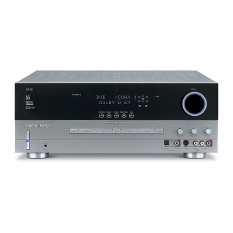
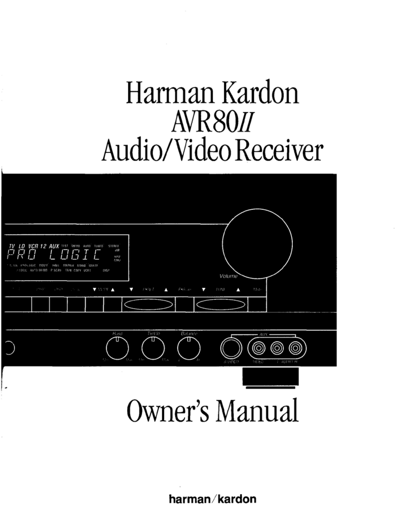
  9. Harman Kardon AVR 30 User manual

Harman Kardon AVR 30 User manual

AVA30.-
Audio
oand
Video
Receiver
Remote
Sensor
A
Tuning
FMef:
yf
MHz:
test:
‘pingor
F2CtUe.]
“EFFECTS
LEVEL”
AMT
[5
BAA
FJ
+
she
ino
ioeclfinerea)
loeb
ets
ety ebs
Seek:
TUNED,
STEREO.
PRESET
[Als]
A
DELAY
ie
Audio
Direct’
Surround
Mode
°-
Effects
Level
+
Center
Mode
Delay.
Time
‘Test
:Tone
Masier
Volume
Treble
Balance
:
Subwoofer
HN
=)|
Center
Level
Rear
Level
2
*
C)
L
x
1a
Max
Mi
CS)
Min
e
eo
Max
.
-
Max
:.
VORE2
VDP
VEP.
SAT:
TV.
tisien
to?
Tape.
t
Tape
2
Tuner
Phono.
'.4
Loudness
poBepe
pb
Oe
lai
bags
Ree
‘trom
ce
se
cee
ere)
foe
Audio
and
Video
Receiver
harman/kardon
OWNER’S
MANUAL
CAUTION
RISK
OF
ELECTRIC
SHOCK
DO
NOT
OPEN
CAUTION:
TO
REDUCE
THE
RISK
OF
ELECTRIC
SHOCK,
DO
NOT
REMOVE
COVER
(OR
BACK).
NO
USER-SERVICEABLE
PARTS
INSIDE.
REFER
SERVICING
TO
QUALIFIED
SERVICE
PERSONNEL.
‘The
lightning
flash
with
arrowhead
symbol,
within
The
exclamation
point
within
an
equilateral
tri-
an
equilateral
triangle,
is
intended
to
alert
the
angle
is
intended
to
alert
the
user
to
the
pres-
user
to
the
presence
of
uninsulated
"dangerous
ence
of
important
operating
and
maintenance
voltage"
within
the
product's
enclosure
that
may
(servicing)
instructions
in
the
literature
accom-
be
of
sufficient
magnitude
to
constitute
a
risk
of
panying
the
appliance.
electric
shock
to
persons.
WARNING:
TO
REDUCE
THE
RISK
OF
FIRE
OR
ELECTRIC
SHOCK,
DO
NOT
EXPOSE
THIS
APPLIANCE
TO
RAIN
OR
MOISTURE.
CAUTION:
TO
PREVENT
ELECTRIC
SHOCK,
MATCH
WIDE
BLADE
OF
PLUG
TO
WIDE
SLOT,
FULLY
INSERT.
ATTENTION:
POUR
EVITER
LES
CHOCS
ELECTRIQUES,
INTRODUIRE
LA
LAME
LA
PLUS
LARGE
DE
LA
FICHE
DANS
LA
BORNE
CORRESPONDANTE
DE
LA
PRISE
ET
POUSSER
JUSQU’AU
FOND.
Manufactured
under
license
from
Dolby
Laboratories
Licensing
Corporation.
Additionally
licensed
under
one
or
more
of
the
following
patents:
U.S.
numbers
3,632,886,
3,746,792
and
3,959,590;
Canadian
numbers
1,004,603
and
1,037,877.
“Dolby”
and
the
double-D
symbol
Od
are
trademarks
of
Dolby
Laboratories
Licensing
Corporation.
Harman
Kardon
AVR30
Date
of
purchase
Purchased
from
Address
of
business
purchased
from
Installed
by
Date
installed
Serial
No.
Thank
you
for
choosing
a
Harman
Kardon
Audio/Video
Receiver.
Your
new
unit
is
an
exceptionally
well-engineered
product
that
will
give
you
years
of
superb
performance.
Save
all
packing
material.
lt
is
essential
for
shipping
should
you
move,
or
in
the
event
the
unit
ever
needs
repair.
U.
S.
and
Canadian
customers
should
use
120
volt
AC
only.
Other
customers
should
use
voltages
appropriate
to
their
area.
Connecting
the
unit
to
an
outlet
supplying
a
higher
voltage
may
create
a
fire
hazard.
Handle
the
Power
Cord
Gently.
@
To
disconnect
the
plug
from
the
AC
outlet,
pull
on
the
plug
itself,
not
on
the
cord.
MM
Disconnect
the
plug
from
the
AC
outlet
whenever
the
unit
is
to
be
left
unused
for
an
extended
period
of
time.
HM
Do
not
place
furniture
or
other
heavy
objects
on
the
cord,
and
avoid
dropping
heavy
objects
on
it.
Also
do
not
make
a
knot
in
the
cord.
Place
the
unit
on
a
firm
and
level
surface.
Avoid
installing
it:
Min
moist
or
humid
places;
Mi
Close
to
heating
equipment
or
in
places
exposed
to
direct
sunlight;
Min
a
direct
draft
from
an
air
conditioner
or
in
other
very
cold
locations;
M@
In
places
subject
to
excessive
vibration
or
dust;
Min
poorly
ventilated
places.
Moving
the
Unit.
Before
moving
the
unit,
be
sure
to
unplug
the
power
cord
from
the
AC
outlet
and
disconnect
all
wires
to
antennas
and
other
componenis.
Do
Not
Open
the
Cabinet.
Do
not
attempt
to
service
this
unit.
Tampering
with
internal
components
can
cause
fire
or
shock,
and
may
void
your
guarantee.
lf
water
or
small
objects
enter
the
unit,
unplug
the
power
cord
immediately
and
consult
an
authorized
Harman
Kardon
service
center.
Using
the
unit
under
such
conditions
may
cause
a
fire
or
shock
hazard.
Cleaning.
Remove
dust
by
wiping
the
unit
with
a
soft,
dry
cloth.
If
necessary,
use
a
soft
cloth
lightly
dampened
with mild
soapy
water;
then
wipe
with
a
dry
cloth.
Never
use
benzene,
thinner,
alcohol
or
other
volatile
agents,
and
avoid
spraying
insecticides
near
the
unit.
TABLE
OF
CONTENTS
Special
Features
Installation
and
Connections
Front
Panel
Controls
Operating
Instructions
System
Remote
Control.
.
Home
Theater
Controller
(HTC)
Using
the
On
Screen
Menu
system
Using
the
Digital
Signal
Processor
-
Setup
Adjustments
Troubleshooting
Specifications
The
AVR30
is
a
very
unique
and
versatile
Audio
and
Video
Receiver.
lt
combines
a
special
switching
system
for
all
your
Audio
and
Video
products
with
a
complete
Recording
switching
system
into
one
unit
that
has
five
fully
discrete
amplifiers,
Dolby
Pro
Logic
Surround,
a
Digital
Signal
Processor,
and
a
remote
control
that
operates
the
AVR30
and
many
other
products
in
your
system.
Feature
Highlights
Mi
DOLBY
Pro-Logic
Surround*
The
AVR380
DOLBY
PRO-LOGIC
Decoding
system
brings
the
theater
surround
sound
experience
to
your
home.
Dolby
Pro-Logic
creates
four-channel
surround
sound
plus
a
true
Center
Channel.
Because
of
this
center
channel,
listeners
in
less
than
ideal
positions
will
still
hear
the
movie
dialogue
coming
from
the
screen.
M@
Digital
Signal
Processor
(DSP)
The
AVR30
includes
a
custom
programmed
Digital
Signal
Processor
for
simulating
the
room
ambience
in
a
variety
of
performance
arenas
from
the
size
of
a
large
stadium
to
the
closeness
of
a
small
club.
Unlike
many
other
Digital
Signal
processors
Special
Features
that
sound
artificial
and
unnatural,
the
AVR30
will
sound
true
to
life,
subtle
and
never
distracting.
The
system
is
easy
to
operate
and
will
yield
realistic
natural
sound
with
any
of
the
available
settings.
Mi
System
Remote
The
System
Remote
controls
AVR30
functions
using
various
one-push
‘commands
or
the
On
Screen
Menu
System.
The
system
remote
also
controls
most
Harman
Kardon
CD
players
and
cassette
players.
HM
Home
Theater
Controller
(HTC)
Remote
The
HTC
is
a
remote
control
that
operates
the
AVR30
through
a
TV
screen
menu
system
and
is
also
preprogrammed
to
control
various
branded
audio
and
video
products.
Mi
On
Screen
Menu
System
A
convenient
control
system
with
visual
conformation
for
selecting
various
components,
modes
and
settings
on
to
the
AVR30.
Mi
Video
Switching
When
an
audio/video
source
is
selected
for
viewing
or
recording,
both
audio
and
video
outputs
are
selected
simultaneously.
Mi
Memory
System
The
AVR30
includes
a
unique
memory
system
that
remembers
each
Digital
Signal
Processor
mode
and
setting
last
used
and
recalls
the
setting
when
selecting
a
"Listen
To"
source.
M@
Ultrawide
Bandwidth
The
AVR30
circuitry
is
designed
to
deliver
extended
frequency
response,
while
keeping
phase
shift
well
outside
the
audible
spectrum.
The
result
is
stereo
imaging
and
clarity
with
remarkably
accurate
spatial
positioning
of
vocals
and
musical
instruments.
Mi
Discrete
Circuitry
For
maximum
design
flexibility
and
highest
possible
performance,
the
amplifier
circuitry
has
been
designed
using
discrete
electronic
components,
not
off-the-shelf
integrated
circuits.
Mi
Low
Negative
Feedback
Conventional
designs
rely
heavily
on
negative
feedback
to
reduce
Total
Harmonic
Distortion.
This
results,
however,
in
excessive
Transient
Intermodulation
Distortion,
audible
in
the
harsh,
grating
quality
of
the
sound.
*Dolby
Prologic
Surround
is
a
trademark
of
DOLBY
LABORATORIES
LICENSING
CORPORATION.
3
Harman
Kardon
keeps
negative
feedback
low
for
smoother,
clearer
reproduction
of
complex
musical
sounds,
such
as
those
of
stringed
instruments.
Mi
HCC
(High
Instantaneous
Current
Capability)
This
enables
the
AVR30
to
maintain
an
undistorted
output
signal
when
driving
Low
Impedance
or
resistive
speaker
loads.
Supplied
Accessories/
Packing
List
System
Remote
Controller
2
Batteries
(size
"AA")
Home
Theater
Controller
(HTC)
4
Remote
Batteries
(size
"AAA")
AM
Antenna
FM
Indoor
Dipole
Antenna
Manual
Safety
Sheet
Warranty
Card
Customer
Response
Card
Mi
2
IR
Remote
Connection
Cables
Right
Lett
Outdoor
FM
Antenna
©)
©)
(2)
O
©)
O
AM
Loop
Antenna
Rear
Speakers
ee
|
Center
Speaker
a
ee
Front
Speakers
; |
Front
Speakers
CR
PEAKERS
|
|_|
if
oF
ee
|
+
|
|
(|_Acizovreore
a
SWITCHED
:
:
|
aol
TOTAL
MAX
120W,1A
oe
O:
S0-.0"
Aaron
SPEAKER
IMPEDANCE
@
>"
c
Je
rd
m
®..
FRONT
A
OR
B:
62
MIN
GND
GND
A &
B:
12Q MIN
CENTER
602
MIN
REAR
4
MIN
AUDIO
EQUIPMENT
f
:
UL
FILE
8148
0-186
‘O
©
i
4
MODEL
NO.:
AVR30
:
HARMAN
KARDON
|
SERIAL
NO.
_
J
4
NORTHRIDGE
2
4
i]
CALIFORNIA,
U.S.A.
Aes
See]
MADE
IN
JAPAN
LISTED
$960
MANUFACTURED
UNDER
LICENSE
FROM
DOLBY
LABORATORIES
LICENSING
CORPORATION.
ADDITIONALLY
LICENSED
UNDER
ONE
OR
MORE
OF
THE
cS)
FOLLOWING
PATENTS:
U.S.
NUMBERS
3,692,986,
3,746,792
AND
3,999,590;
CANADIAN
NUMBERS
1,004,603
AND
1,037,877,
"DOLBY"
AND
THE
OOUBLE-D
SYMBOL
[IJ
ARE
TRADEMARKS
OF
DOLBY
LABORATORIES
LICENSING
CORPORATION.
TO
TO
me
ewes
REAR
“=
FRONT
ae
___|
STEREO
‘
STEREO
Stereo
Amplifier
SPEAKERS
\
Stereo
Amplifier
_
SPEAKERS
AUDIO
OUT
ff
_MIDEO
OUT
Il
Se
\We
Indoor
FM
Antenna
(Included)
:
OO
0
Oo
CO
\&
%
Sy
%
2
"
.
are
|e
ieee
eee
3
\
to
\
ae
sc
econo
“SUBWOOFER
‘
bx
CENTER
nee
:
eae
SPEAKER
SPEAKER
eon
Satellite
Receiver
——
— —
Stereo
Amplifier
Mono
Amplifier
CEE
LINE
Na
_CASSETTE
LINE
OUT
|
I
a
*
Cassette
Deck
2
neater
ene
e
tenets
ndatintcneetretee
cnet
NHRD
HOt
I
any
. *
*
Connect
the
"Inputs"
of.
‘this
unit
to
the
Video
Recorder
1
Video
Recorder
2
-
"Outputs
‘of
the
AVR30;
and:
vice-versa
|
Fe
for
the,
wOutputs":
of
this.
unit.
Pi
Loreen
.
power:
outlets.
ie
a
23¢
_
Noltage
system
§
switch.
See
WCR
AUDIO
OUT.
a
CB
VIDEO
OUT
ee
as
VER
AUDIO
IN
wat
CR
AUDIO
OUT.
oe
a
oom
Ea
OO
IN
neon
ot,
VIDEO
OUT...
CENTER
SPEAKER
FR
‘|
AG
120V/60Hz
CENTER
GND
SWITCHED
TOTAL
MAX
120W,1A
CAUTION
SPEAKER
IMPEDANCE
FRONT
A
OR
B:
62
MIN
p
GND
A
&
B:
122
MIN
CENTER
69
MIN
REAR
42
MIN
/\
ze
/"\
DO
NOT
OPEN
MODEL
NO.:
AVR30
HARMAN
KARDON
|
—SERIAL_NO._
NORTHRIDGE
CALIFORNIA,
U.S.A.
MADE
IN
JAPAN
™
©
>)
@
GND GND
DOLGY
LABORATORIES
LICERSING
CORPORATION.
OUTPUT
_LD
AUDIO
OUT
=
=
Monitor
TV
;
tome
TO
“Remote
in"
on
:
other
H/K
components
aa
get
:
to
be
controlled.
SS
See
TV
VIDEO
OUT
|
Turntabie
“TV
VIDEO
IN
Re
RR
a
Par
we
External
Infrared
Sensor
SS
a
Remote
Conitrol
The:
220/230.
version
1
does
em
nelude
harman/kardon
AVRA30
Audio
and
Video
Receiver
fe]
oe
;
A-8B
TS
eee
Speaker
Bass
Treble
Headphones
Ue
General
Information
Placement:
Unit
may
be
placed
on
top
of
or
beneath
other
stereo
components,
so
long
as
Its
placement
meets
the
cooling
requirements
of
the
component
beneath
it.
AC
Power
Plug
the
cord
into
a
polarized
wail
socket,
or
polarized
extension
cord.
7
2
3 4
D
@
a
Cp
g
5
6
7
8
Audio
Direct
Surround
Mode
-
Effects
Level
+
Center
Mode
Delay
Time
Test
Tone
Remote
Sensor
FM
f
SEEK
TUNED
stereo
Preset
EEE
aaa
Balance
Subwoofer
Leve/
Center
Level
Rear
Level
Of
AB
@ °
e e
e@
e
Cy"
*
C
)
C
)
C
)
(
)
=
-@
et
-@
et
Le
ef
Min
@
@
Max
Min
@
@
Max
Min
@ @
Max
Simulcast]
VCR
1
|
VCR
2
|
VDP
VoP
SAT
TV
a U U O O 0 Q
AC
Outlets
(120
Volt
Version
Only)
2
SWITCHED
OUTLETS
and
1
UNSWITCHED
OUTLET
Use
these
to
connect
the
power
cords
from
your
components
to
this
unit.
The
power
to
the
SWITCHED
outlets
is
controlled
by
this unit's
POWER
switch
or
the
provided
remote-control
transmitters
POWER
key.
These
outlets
will
supply
power
to
any
MHz
zest
pinecr
[
ciue
|
,_
EFFECTS
LEVEL
ae
G7
C+
Kee
[ero
ooe
linear)
chet
[MALL
}
[Wide] [Nona]
[PHaNTOn)
S
bh
gow
Listen
to]
Tape
7
Tape
2
Aux
cD
Tuner
Phono
|
Loudness
Q
U
0
0
Q
U
Ree
from
pe
fo]
a
aT
D
q
(aso
Master
Volume
EFF
component
whenever
this
unit
is
turned
on.
The
power
to
the
UNSWITCHED
outlet
can
not
be
controlled
by
this
unit's
POWER
switch
or
the
provided
remote-control
transmitter’s
POWER
key.
The
maximum
power
(total
power
consumption
of
components)
that
can
be
connected
to
the
SWITCHED
AC
OUTLETS
is
120
watts.
O
~
AN
Mono
The
maximum
power
(total
power
consumption
of
components)
that
can
be
connected
to
the
UNSWITCHED
AC
OUTLET
is
180
waits.
Connecting
Audio
Components
(see
the
installation
and
connections
diagram
on
page
4
for
details)
1.
Make
sure
the
AVR30
and
other
components
are
turned
off.
2.
Connect
each
component’s
Output
jacks
to
the
corresponding
"In"
jacks
on
the
back
of
your
receiver.
Use
the
white,
black
or
gray
plugs
to
connect
Left
channel
jacks;
use
the
red
plugs
for
Right
jacks.
Connect
your
turntable
to
the
jacks
marked
"Phono".
Also
connect
the
ground
wire
from
the
turntable
to
the
terminal
marked
"GND"
next
to
the
Phono
jacks.
Antenna
Installation
Select
the
FM
antenna
that
best
meets
your
needs.
1.
An
indoor
dipole
antenna
is
supplied
with
your
AVR30.
This
will
work
well
if
you
are
located
ina
strong
signal
area.
2.
Other
indoor
antennas
are
available
which
may
improve
reception
by
offering
greater
positioning
flexibility.
3.
If
reception
is
unsatisfactory
using
indoor
antennas,
an
outdoor
antenna
should
be
installed.
4.
Alternatively,
you
may
connect
to
an
FM
cable
antenna,
if
available.
Connect
the
EM
_
antenna.
Connect
the
two
leads
of
the
antenna
to
the
two
screw-down
terminals
marked
"FM
300QBAL".
If
you
wish
to
connect
a
cable
antenna,
connect
it
to
the
location
marked
"FM
75Q
UNBAL"
(see
antenna
connection
diagram
for
details).
Position
the
FM
antenna
for
optimum
reception.
_
Reception
from
all
of
the
above
antennas
(except
the
cable
antenna)
may
be
improved
by
re-positioning
them.
Try
your
antenna
in
different
positions
to
find
the
one
in
which
most
of
your
desired
broadcast
stations
have
high
signal
strength
readings
and
good
sound
quality.
Connect
the
AM
Antenna.
Your
receiver
comes
with
an
AM
loop
antenna
which
provides
good
reception
in
most
locations.
For
best
results,
place
this
antenna
away
from
the
unit
and
away
from
contact
with
any
metal
object.
|
In
areas
where
AM
signals
are
weak,
an
outdoor
AM
antenna
may
improve
sound
quality.
Connect
the
AM
antenna
leads
to
the
screw-down
terminals
marked
"AM"
on
the
back
of
the
AVR30
(see
antenna
connection
diagram
for
details).
SPEAKER
INSTALLATION
This
unit
is
designed
to
work
with
6
to
16
ohm
impedance
speakers
in
the
front
and
4
to
16
ohm
speakers
in
the
rear.
For
best
performance,
use
high
quality
speaker
cables.
However,
ordinary
copper
wire
can
be
used
if
the
gauge
meets
the
following
requirements:
Wire
Lenth
Gauge
Up
to
8
feet
18
AWG
Up
to
12
feet
16
AWG
Up
to
20
feet
14
AWG
10-12
AWG
custom
speaker
cable
Over
20
feet
NOTE:
Avoid
coiling
excess
wire
with
or
near
line
level
hook-up
cords.
Connect
the
first
pair
of
front
speakers
to
receiver
terminals
marked
"Speaker
System"
"A".
1.
Note
the
difference
between
the
two
conductors
in
each
cable:
different
colored
insulation,
ridged
insulation,
or
colored
yarn.
2.
Connect
the
front
right-hand
speaker
to
the
receiver,
being
sure
to
connect
the
positive
terminal
on
the
speaker
to
the
terminal
marked
“Front
Speakers"
"Right"
on
the
receiver,
and
the
negative
or
ground
terminal
on
the
speaker
to
the
corresponding
"GND"
terminal
on
the
receiver.
3.
Connect
terminals
on
the
front
left-hand
speaker
to
the
"Front
Speakers"
"Left"
and
corresponding
"GND"
terminals
on
the
receiver,
again
being
careful
to
maintain
correct
polarity.
To
connect
a
second
set
of
speakers:
IMPORTANT:
When
connecting
pairs
of
front
speakers
to
speaker
systems
"A"
and
"B,"
determine
the
impedance
of
each
pair
by
looking
on
the
back
of
the
speakers,
or
in
your
owner's
manual,
or
by
contacting
your
dealer
or
manufacturer.
Speaker
pairs
A
and
B
can
be
played
simultaneously
only
when
the
impedance
of
speakers
A
and
B
are
12Q
or
greater.
WARNING:
Do
not
piay
both
sets
of
front
speakers
simultaneously
except
as
recommended
above.
Receiver
may
overheat.
4.
Connect
terminals
on
the
Center
Speaker
to
the
"Center"
and
corresponding
"GND"
terminals
on
the
Receiver.
5.
Connect
terminals
on
the
Rear
Left
and
Right
Speakers
to
the
corresponding
Rear
"Left,"
"Right"
and
"GND"
terminals
on
the
Receiver.
Subwoofer
Out
Connect
a
powered
subwoofer
to
these
jacks.
This
output
may
also
be
used
for
any
external
component
requiring
a
full
bandwidth
line-level
input.
Wired
Remote
Control
To
control
your
AVR30
with
an
external
infrared
remote
sensor,
connect
the
wire
from
the
remote
sensor
to
the
“Remote
In"
jack
on
the
back
panel.
Or,
if
you
have
a
stereo
component
with
a
built-in
infrared
remote
sensor
and
a
“Remote
Output"
jack,
it
may
be
possible
to
connect
this
jack
to
the
"Remote
In"
jack
of
your
AVR30.
All
Harman
Kardon
products
with
"Remote
In"
and
"Remote
Out"
jacks
are
compatible
with
one
another,
except
for
the
HD7400
CD
Player,
Citation
22,
Citation
24
and
Citation
25.
Other
manufacturers’
remote
sensors
may
not
be
compatible,
but
It
will
not
hurt
to
experiment.
A
second
wire
may
be
used
to
connect
your
AVR30’s
"Remote
Out"
Jack
to
the
"Remote
Input"
of
another
stereo
component.
Continue
this
process
to
include
additional
components
(if
compatible).
To
control
your
AVR30,
you
may
use
one
of
the
remote
controls
supplied
with
the
AVR30.
You
may
use
the
HTC
to
control
other
components,
such
as
TVs,
VCRs,
laser
disc
players,
etc.
Front
Panel
Controls
~xmo
Bass
Treble
Center
Delay
Volume
==
Turn
to
increase
or
Turn
to
increase
or
decrease
the
Press
to
select
the
desired
center
mode
(NORMAL,
Press
to
select
the
appropriate
Dolby
Turn
to
raise
or
decrease
the
proportion
PHANTOM,
or
WIDE).
See
page
17
for
deiails.
Pro
Logic delay
time
(15,
20,
or
30ms).
lower
system
output
of
low
frequency
sound.
|
»
Speaker
_
|
Tum
to
select
either
of
two
,
|
sets
of
speakers,
or
both,
|
or
neither
(headphone
|
|
output
only).
||
Power
'
|
Press
to
turn
the
unit
on
_
4
(Green
Indicator)
and
off
of
AB
Headphones
Headphone
Jack
Plug
in
headphones
if
desired
(with
Speaker
switch
in
"Off"
position,
output
is
supplied
only
proportion
of
high
frequency
sound.
|
|
(Orange
Indicator)
(for
use
with
|
2
t
romete
control,
see
page
12.
(Gorey
SURROUND)
TOS
Speaker
A+B
|
Shift
A-B
»
Allows
you
to
access
|
16
pre-selected
stations
|
using
the
8
preset
buttons.
|
Memory
———~
_
Press
to
set
|
a
new
preset
Bass
ny
VCR
1
VCR
2
UO
OU
|
Simulcast
“Rec
From”
|
Press
to
record
from
a
video
/
source
combining
the
audio
_
from
a
different
source.
station
in
memory.
Treble
6
Audio
Direct
=~
Press
this
bution
to
bypass
all
surround
sound
processing.
Preset
Buttons
Press
to
access.
pre-selected
stations.
Balance
|
Balance
-
_
Turn
to
sdaat
reuaiive
output
|
level
of
left
and
right
speakers.
"Record
From"
Selector
Press
desired
key
to
choose
source
for
recording.
Subwoofer
Level
Surround
Press
this
bution
to
select
the
desired
surround
mode
(MOVIE,
HALL,
THEATER,
etc.).
Effect
Level
+
/
-
Press
these
buttons
to
adjust
the
"liveness"
of
the
glial.
Signal
Processor.
Center
Level
e
q
ot
i “
%
e
3
fi
YM
cis
: :
|
XS
5
;
S,
ssh
pic
corre
reunite
oc
bt
eee
sn
RE
a
A
NE
ROR
ESB
SSSEEISER
EE
Sac
noe
onan
PacRNn
SIN
ELSES
OI
ERI
ZEEE
ERRE
ESB
e
Subwoofer
Level
Turn
to
increase
or
decrease
the
subwoofer
output
level
relative
to
the
front
speakers
connected
to
the
AVR30.
"Listen
To"
Selector
volume.
-
Effects
Level
+:
|
Center
Mode
Dek
gs
Rear
Level
t
_
Turn
to
increase
or
?
|
decrease
the
rear
speaker
level
|
relative
to
the
front
speakers
!
connected
to
the
AVR30.
See
page
16
for
further
information.
FM/AM
~
Press
to
select
AM
or
FM
reception.
Test
Tone
Press
to
turn
on
the
test
tone
used
for
Speaker
level
adjustment
(see
page
18).
Time
*
i
ast
Tone
Rear
Level
Center
Level
Video
L
to
headphones).
Simulcast
"Listen
To"
Press
to
view
a
video
source
while
listening
to
separate
audio
source.
Press
desired
key
to
choose
listening
source.
Turn
to
increase
or
decrease
the
center
speaker
level
relative
to
the
front
speakers
connected
to
the
AVR30.
Press
A
to
tune
to
stations
with
higher
frequencies;
press
W
for
lower
frequencies.
Seek-Stereo
Press
to
select
Seek
tuning
in
stereo,
or
manual
tuning
in
mono.
|
Master
Volume
-
Mono
Press
to
hear
input
from
any
source
in
mono.
LOUCNESS
eres
Press
to
improve
sound
quality
when
listening
to
your
system
at
low
volume.
|
Operating
Instructions
Listening
to
Audio
or
Video
Sources
1.
With
Power
on
and
the
Master
Volume
knob
at
minimum
level,
select
speaker
setting
A,
B,
both
or
neither
(for
headphone
use).
2.
Press
the
"Listen
to”
button
that
corresponds
to
the
component
you
wish
to
hear.
SAT
TV
Listen
to|
Tape
f
Tape
2
a
a
i
ee
3.
Begin
playing
the
desired
component.
4.
Adjust
the
Master
Volume
to
the
desired
level.
9.
When
listening
at
low
volume,
you
may
wish
to
activate
the
Loudness
button.
This
boosts
low
frequencies
to
improve
the
apparent
balance
of
low,
mid
and
high
frequencies.
6.
Adjust
Bass
and
Treble
controls
as
desired.
Adjusting
the
AM/FM
Tuner
With
the
"Tuner"
Listen
to
button
selected:
5
1.
Select
AM
or
FM
by
pressing
the
corresponding
button.
2.
Use
the
A
and
¥
buttons
to
tune
to
desired
frequency.
Or
use
the
station
Preset
buttons
as
shown
below.
3.
When
tuning
FM
stations,
begin
with
Seek-Stereo
function
on
("Seek"
will
light
on
the
Display
Panel).
In
this
mode,
pressing
A
(or
¥)
will
tune
your
unit
to
the
next
higher
(or
lower)
strong
station.
To
tune
to
stations
too
weak
to
be
received
in
Seek-Stereo
mode,
turn
Seek-Stereo
off.
Then
use
A
and
VW
buttons
to
reach
the
desired
frequency.
NOTE:
With
Seek-Stereo
off,
all
broadcasts
are
received
in
mono
(this
eliminates
the
excessive
noise
that
results
when
weak
stations
are
received
in
stereo).
When
you
tune
to
a
new,
stronger
station,
be
sure
to
turn
Seek-Stereo
back
on.
Using
the
Preset
Buttons
Your
AVR30
allows
you
to
store
16
station
settings
and
quickly
access
them,
using
the
8
Preset
buttons
along
with
the
Shift
A-B
button.
The
Preset
stations
are
designated
by
the
letter
A
or
B,
followed
by
a
number
from
1
to
8.
Any
AM
or
FM
station
can
be
stored
in
any
preset
button.
Jo
enter
a
station
in
"memory":
1.
Tune
to
the
desired
station.
2.
Be
sure
Seek-Stereo
setting
is
the
one
desired.
3.
Press
the
Shift
A-B
button
to
display
the
desired
letter.
4.
Press
the
Memory
button
("Preset”
will
flash
for
about
8
seconds).
5.
With
"Preset"
flashing,
press
the
desired
numbered
Preset
button.
NOTE:
When
a
station
is
set
in
memory,
the
Seek-Stereo
setting
is
also
saved.
Subsequently,
each
time
a
station
is
recalled
using
a
Preset
button,
the
tuner
automatically
switches
to
the
original
seek-Stereo
setting
for
that
station.
To
Change
a
preset
station:
Simply
enter
the
new
station
using
the
"To
enter
a
station
in
memory"
procedure
above.
The
old
station
is
automatically
erased.
To
access
a
preset
station:
Press
the
Shift
A-B
button
to
display
the
correct
letter.
Then
press
the
desired
numbered
preset
button.
NOTE:
Preset
stations
are
stored
indefinitely
while
the
unit
is
connected
to
a
live
AC
source,
and
for
approximately
1
week
when
the
unit
is
unplugged.
"Listen
To"
Simulcast
The
simulcast
button
allows
the
user
to
view
a
video
source
while
listening
to
audio
from
a
purely
audio
source.
For
example,
suppose
that
a
concert
is
broadcast
on
TV
witha
stereo
FM
radio
simulcast.
To
listen
to
the
simulcast
select
TV
as
the
video
source,
press
simulcast
and
press
Tuner
as
the
audio
source.
Any
further
press
of
the
audio
or
video
"listen
to"
buttons
will
cancel
the
simulcast
operation
automatically.
11
Making
Recordings
To
make
a
recording
on
either
a
tape
deck
or
VCR,
simply
press
the
"Rec
From”
button
that
corresponds
to
the
piece
of
equipment
you
wish
to
record
from.
The
"Rec
From"
output
will
be
supplied
to
Tape
1
and
Tape
2,
and
to
VCR
1
and
VCR
2
devices,
enabling
you
to
record
on
any,
or
all
simultaneously.
(a)
To
record
from
one
tape
device
to
another,
press
the
Rec
From
button
corresponding
to
the
"Rec
From"
(play)
device.
(b)
By
selecting
different
sources
for
"Listen
to"
and
Rec
From,
you
may
listen
to
one
audio
or
video
component,
while
recording
from
another.
(c)
Make
videotape
recordings
from
TV,
video
disc
player,
video
cassette
player,
satellite
or
second
VCR
in
—
the
same
manner
described
above,
simply
by
pressing
the
appropriate
Rec
From
button.
With
equipment
installed
as
outlined
in
this
booklet,
both
audio
and
video
output
are
supplied
to
"VCR
1"
and
2.
"Record
From"
Simulcast
"Record
From”
Simulcast
allows
the
user
to
record
video
from
one
source
such
as
the
Video
Cassette
Player
(VCP)
input,
while
adding
audio
from
another
source
such
as
the
CD
player.
To
operate
record
simulcast,
select
a
Rec
From
Video
source
such
as
"VCP",
press
the
record
"Simulcast"
button
and
press
the
"Rec
From"
audio
source
such
as
"CD".
Any
further
press
of
the
"Rec
From"
buttons
will
cancel
"Record
From"
"Simulcast"
mode.
|
|
|
System
Remote
Control
The
System
Remote
Control
The
System
Remote
includes
many
one-touch
keys
that
allow
for
easy
control
of
the
AVR30
and
other
Harman
Kardon
Cassette
and
CD
Players.
The
System
Remote
Control
also
includes
five
keys
which
allow
all
the
major
"On
Screen"
functions
of
the
AVR30
to
be
controlled
through
the
use
of
a
menu
system
displayed
on
your
Video
Monitor.
Operation
of
the
On
screen
Menu
system
is
described
on
page
14.
~Mute
key”
~«-
Volume
and
Level
Power
on/off
Key
14
2
|
control
keys
mika
Tuner
gies
"Listen
to"
Source
_
il
function
keys
||)
y
«On
Screen
Menu
control
keys.
See
"Using
the
On
Screen
Menu
system"
section
for
operation
details.
j=
AM/FM
tuner
(T=1
f=]
function
keys
Harman
Kardon
=e
|
Cassette
transport
function
keys
++
Digital
Signal
ProLogic
Processor
Harman
Kardon
m=
function
keys
C/
D
transport
|
'
Movie
Effects
function
keys
(COE
Co
Ed
Hall
Center
Delay
Test
;
*Note:
The
AVR30
volume
control
LED
will
flash
when
the
"mute"
function
is
on.
The
Home
Theater
Controller
The
home
theater
remote
is
preprogrammed
with
the
product
codes
necessary
to
operate
almost
all
other
remote
controlled
products
that
are
connected
to
the
AVR30,
even
if
the
units
are
not
manufactured
by
Harman
Kardon.
The
controller
also
operates
the
"On
Screen
Menu
System"
with
equal
ease
and
comfort.
The
device
keys
give
access
to
the
various
components
and
allow
them
to
be
operated
directly
by
the
HTC.
Home
Theater
Controller
Remote
Operation
The
operating
and
product
code
loading
instructions
for
the
HOME
THEATER
CONTROLLER
remote
are
given
in
a
separate
booklet
called
the
"Home
Theater
Controller
Owner’s
Manual
and
product
code
book."
13
Home
Theater
Controller
(HTC)
Remote
Operating
Conditions
Both
remote
control
units
operate
effectively
within
a
distance
of
7
meters
(23
feet)
and
an
angle
of
30°
from
the
AVR30.
Using
the
control
near
fluorescent
lights
may
shorten
this
range,
as
will
any
dust
or
dirt
that
accumulates
on
the
front
of
the
remote
control,
or
the
"Remote
Sensor"
area
of
the
AVR30.
Also
avoid
blocking
the
line
of
sight
between
the
AVR30
and
remote.
The
system
remote
control
unit
is
powered
by
two
(2)
"AA"
batteries,
included
in
the
carton
with
your
AVR30.
The
Home
Theater
Controller
is
powered
by
four
(4)
"AAA"
batteries,
included
in
the
carton
with
the
AVR30.
When
you
replace
weak
batteries,
replace
all
at
the
same
time.
When
the
remote
is
to
be
unused
for
an
extended
period,
remove
the
batteries
to
prevent
damage
from
corrosion.
*Note:
The
AVR30
volume
control
LED
will
flash
when
the
"mute"
button
is
on.
Power
Key
——-}~!
Device
|||
Keys
Remote
Programming
="
Keys
harman/kardon
=
AVR30
Volume,
Level
and
Mute”
Keys
~
On
Screen
Menu
Control
keys
_
TV
or
Cable
Box
Channel
Control
Key
AVR30
AM/FM
Tuner
Control
-
Tuner
bank
Shift
Key
_
TV,
Cable
Box
or
AVR30
Channel
or
Preset
Selection
Keys
ri
-
Transport
Control
Keys
|
__STOP
PAUSE
VD)
|
>
HOME
THEATER
CONTROLLER
|
|
|
Using
the
On
Screen
Menu
System
Starting
the
On-Screen
Menu
System
|
1.
Connect
the
AVR30
to
the
TV
and
turn
on
the
TV.
Turn
on
the
AVR30.
2.
Press
the
remote
control
"Enter"
button
to
display
the
on-screen
"Menu"
system.
3.
Pressing
the
up/down
keys
highlights
items
to
be
selected
or
changed.
4.
Some
menu
items
use
the
left/right
keys
to
step
through
the
available
options
on
the
currently
highlighted
line.
5.
Press
"Enter"
to
activate
the
desired
|gifelglifelaicsxe)
option.
Note:
Use
the
up/down
keys
to
move
the
cursor
to
"Return
to
the
Main
Menu”
or
"Menu
Off"
and
press
"Enter"
to
return
to
the
main
menu
or
exit
the
menu
system.
Note:
"Surround
Sound"
and
"Test
Tone"
screens
can
only
be
selected
with
"Audio
Direct"
in
the
"Off"
mode.
MAIN
MENU
B>INPUT
SELECTOR
=
REC
OUT
SELECTOR
AUDIO
DIRECT
->
OFF
Use
the
left/right
arrow
keys
to
choose
the
component
to
be
listened
to
**__**
(CD,
VCR
1,
TAPE
1,
TAPE
2,
VCP
etc.).
Press
"Enter"
to
activate
the
highlighted
item.
INPUT
SELECTOR
;
RB
AUDIO
**VvDP*
=
Ph
=
VIDEO
**VDP*
iS
RETURN
TO
MAIN
MENU
SURROUND
SETTING
|!
TEST
TONE
MENU
OFF
MAIN
MENU
INPUT
SELECTOR
PREC
OUT
SELECTOR
+
AUDIO
DIRECT
->
OFF
SURROUND
SETTING
TEST
TONE
MENU
OFF
Use
the
left/right
arrow
keys
to
choose
the
component
to
be
recorded
from
(CD,
VCR
1,
TAPE
1,
TAPE
2,
etc.).
Press
"Enter"
to
activate
the
highlighted
item.
MAIN
MENU
INPUT
SELECTOR
REC
OUT
SELECTOR
BAUDIO
DIRECT
->
OFF
SURROUND
SETTING
TEST
TONE
MENU
OFF
Use
the
right
hand
arrow
key
to
move
to
the
ER)
"ON/OFF"
Position
desired.
MAIN
MENU
««
SURROUND
SETTINGS
rene
the
orn
rennel
to
ey
INPUT
SELECTOR
/f
€
surround
mode
or
setting
to
be
REC
OUT
SELECTOR
Tah
/
Ne
adjusted.
AUDIO
DIRECT
->
OFF
Use
the
left/right
arrow
keys
to
eget
alae
a
SETTING
“Tr
choose
the
desired
setting.
Press
"Enter"
to
activate
the
MENU
OFF
ee
highlighted
item.
*
TEST
TONE
MAIN
MENU
/
|
>
ON
OFF
INPUT
SELECTOR
,
Use
the
right
hand
arrow
key
to
REG
OT
Ge
ECTOR”
f
L
FRONT
R
FRONT
|||
move
the
arrow
to
the
"OFF"
AUDIO
DIRECT
->
OFF
:
position
and
return
to
the
main
SURROUND
SETTING
;
&\
CENTER
menu.
BP
TEST
TONE
_....
fr
MENU
OFF
14
Purpose
of
the
Digital
Signal
Processor
The
AVR30
incorporates
a
sophisticated
Digital
Signal
Processor
which
allows
the
user
to
expand
and
shape
the
soundfield
from
audio
and
video
sources.
The
unit
has
7
modes,
two
Dolby
Pro
Logic
modes
and
five
Digital
Signal
Processor
modes.
This
unit
simulates
different
size
performance
venues
such
as
a
small
night
club
or
a
small
movie
theater
or
even
a
large
stadium
with
a
clarity
and
realism
unheard
in
other
processors.
Description
of
Dolby
Pro
Logic
Surround
The
Dolby
Pro
Logic
in
this
system
is
similar
to
professional
Dolby
Stereo
decoders
used
in
movie
theaters.
The
Dolby
Pro
Logic
Surround
system
employs
four-channels:
the
left
and
right
main
channels,
the
center
channel
(to
characterize
dialogue),
and
the
rear
surround-
sound
channels
(to
characterize
sound
effects,
background
and
other
ambient
information).
Dolby
Surround
is
encoded
on
the
sound
track
of
commercially
available
video
cassettes
and
video
discs
as
well.
When
you
play
a
15
Using
the
Digital
Signal
Processor
(DSP)
harman/kardon
§[
Jeli
Lisle
a
lt
Fb]
a
el:
wa
=
et
System
Remote
Control
source
encoded
with
Dolby
Surround
on
your
home
theater
system
with
the
Dolby
Pro
Logic
Surround
mode
on,
the
AVR30
decodes
the
signal
and
steers
the
surround-sound
effects.
Oar
Speaker
of_
AB
a
Headphones
Dolby
Pro
Logic
Surround
mode
is
also
most
effective
on
not
sources
encoded
with
Dolby
Surround.
(MOPRO
Loaic][THeaterR)
CS So
SA
[WIDE]
[NOAM]
[PHANTOM]
Bass
Trable
Balance
Subwoofer
Level
&
*
e
QQ
02
QOL
oT
1
“4
2
VOP
Tape
1
Tape
2
te
tetetetete.
Alec
from
AVR30
~
EFFECTS
LEVEL
i
Notes
on
Operation
of
Surround
Modes
Mi
in
the
CLUB,
THEATER,
HALL
and
STADIUM
modes
the
center
speaker
does
not
function.
Mi
When
a
monaural
(mono)
sound
source
is
played
in
the
DOLBY
PRO
LOGIC
mode,
sound
is
heard
only
from
the
center
speaker.
However,
if
the
PHANTOM
mode
is
selected,
the
two
front
speakers
both
put
out
a
monaural
signal.
Adjusting
"Effects
Level"
The
effects
level
has
5
settings
which
can
be
changed
with
the
remote
control
direct
keys,
on-screen
menu,
or
the
front
panel
key
of
the
AVR30.
The
effects
level
setting
—
alters
the
liveness
or
reflectivity
of
the
listening
space
being
simulated.
An
effect
level
seiting
of
five
is
equivalent
to
a
room
with
highly
reflective
surfaces
that
absorb
little
sound
and
thus
produces
more
audible
ambience.
An
effect
level
setting
of
1
is
equivalent
to
a
room
with
walls
which
have
coverings,
such
as
drapes
or
acoustic
tiles,
that
will
quickly
absorb
sound
reflections.
Selecting
Surround
Mode
Surround
modes
can
be
selected
by
any
of
three
methods:
Mi
The
direct
"DSP"
keys
on
the
"System
Remote
Control"
Mi
The
"ON
SCREEN"
menu
system.
Mi
The
"Surround
Mode"
push
button
on
the
front
panel
of
the
AVR30
itself.
Note:
"Audio
Direct"
must
be
switched
off
before
any
of
the
surround
modes
can
be
used.
selecting
Delay
Time
The
15ms,
20ms
and
30ms
Time
Delay
can
be
selected
with
any
of
three
methods:
Mi
The
direct
"DSP"
keys
on
the
"System
Remote
Control"
Mi
The
"ON
SCREEN"
menu
system.
Mi
The
"Delay
Time"
push
button
on
the
front
panel
of
the
AVR30
itself.
Adjusting
the
Rear
Level
In
some
surround
modes
it
may
be
desirable
to
adjust
the
rear
speaker
level.
This
can
be
done
by
using
the
remote
control’s
rear
level
keys
or
adjusting
the
rear
level
knob
on
the
front
panel.
Note
the
rear
channel
does
not
function
when
Audio
Direct
mode
is
on.
Description
of
each
mode
MODE
FEATURES
DOLBY
PRO
LOGIC
|This
mode
is
effective
for
play
of
sources
encoded
with
Dolby
Surround.
The
AVR30
employs
a
digital
surround
MOVIE
This
mode
is
effective
for
play
of
sources
encoded
with
Dolby
Surround.
In
addition
to
the
normal
Dolby
Pro
Logic
surround
features,
this
mode
simulates
the
ambience
of
a
35mm
movie
theater,
giving
the
sense
of
hearing
the
movie
in
a
large
space.
THEATER
This
mode
provides
the
listener
with
the
sense
of
being
in
a
1200
seat
theater.
The
sound
is
dynamic
and
rich
in
ambience.
HALL
This
mode
brings
the
experience
of
a
5000
seat
concert
hall
to
your
home.
The
sound
is
expansive
and
rich
in
ambience.
rN
mode
provides
the
ambience
of
a
large
20,000
seat
Note:
The
Audio
Direct
mode
bypasses
all
surround
effects
and
outputs
unprocessed
signal
from
the
left
and
right
front
speakers.
“Audio
Direct"
must
processing
system
that
improves
separation
and
steers
SIMULATED
This
mode
is
effective
for
creating
a
simulated
surround
SURROUND
field
from
a
monaural
input
signal.
It
can
be
used
to
add
excitement
to
monaural
television
broadcasts
or
movies.
stadium.
The
sound
will
be
largely
ambient
in
a
very
big
be
turned
off
before
any
of
the
surround
modes
can
be
used.
the
sound
in
a
smooth
and
natural
manner.
CLUB
This
mode
provides
the
listener
with
the
ambience
of
a
small
club
with
about
300
seats.
sounding
16
SPEAKER
BALANCE
ADJUSTMENT
This
procedure
gives
the
steps
necessary
to
adjust
the
sound
output
level
balance
between
the
front,
center,
and
rear
speakers.
After
the
adjustment
is
correctly
completed,
the
sound
level
heard
at
the
listening
position
will
be
the
same
from
each
speaker.
Taking
the
time
to
do
this
setup
will
yield
the
best
performance
possible
out
of
the
Digital
Signal
Processor.
Set
Master
volume
to
the
"Min"
position.
Master
Volume
Min
»
e
Max
Select
the
front
speakers
to
be
used.
Speaker
of
A_B
A+B
17
Setup
Adjustments
Set
to
the
center
position.
Bass
Treble
e@
e
C)
+
J
+
Set
to
the
center
position.
Balance
e
OC
Power
on.
Loudness
off.
Phono
Loudness
il
E
rd
Audio
Direct
button
off.
Audio
Direct
Set
Surround
Mode
to
Dolby
"Pro
Logic”.
Surround
Mode
Select
the
Center
Mode.
Center
Mode
Select
the
center
mode
depending
on
your
speaker
configuration
(see
Speaker
Configuration
section
on
page
19).
Details
on
the
modes
are
give
in
the
Note
below.
Notes
for
Center
Mode
Selection
5
speaker
Configurations
Normal:
Select
this
mode
when
the
center
speaker
is
smaller
than
the
other
front
speakers.
In
this
mode
bass
frequencies
will
come
only
from
the
left
and
right
front
speakers.
Wide:
Select
this
mode
when
the
center
speaker
is
approximately
the
same
size
as
the
other
front
speakers.
This
mode
sends
bass
tones
to
all
of
the
front
speakers.
4
speaker
Configurations
PHANTOM:
Select
this
mode
when
you
do
not
have
a
center
speaker.
In
this
mode,
the
center
speaker
information
will
come
from
the
left
and
right
front
speakers.
Balancing
the
Speaker
System
Set
Test
Tone
button
to
"On".
Test
Tone
—&>
Note:
The
"Mute"
function
is
inoperative
during
the
"Test
Tone"
operation.
The
following
steps
should
be
set
with
reference
to
your
listening
position.
:
Turn
up
the
Volume
by
using
the
remote-control.
You
will
hear
a
test
tone
(pink
noise)
that
will
continuously
switch
from
speaker
to
speaker
in
a
clockwise
direction.
[|
CL
RR
LEVW
VOLW
Adjust
the
balance
control
for
equal
sound
level
from
the
left
and
right
front
speakers
at
your
normal
listening
position.
Balance
L
»
of
Adjust
the
center
level
control
so
that
the
sound
from
the
center
speaker
is
the
same
level
at
your
normal
listening
position,
as
the
sound
from
the
left
and
right
front
speakers.
The
"Center"
level
cannot
|
be
adjusted
if
phantom
mode
is
being
used.
Center
Level
Min
e
o
Max
Adjust
the
rear
speaker
level
to
be
equal
to
the
level
of
the
front
speakers
using
the
rear
level
keys.
RLEV@&~
VOL
RA
LEVW
VOLWW
Set
Test
Tone
button
to
"Off".
Test
Tone
Notes:
Once
the
setup
is
complete
use
the
AVR30’s
Volume
Control
to
adjust
listening
volume.
The
Volume
Control
adjusts
the
rear,
center
and
front
speakers
simultaneously.
The
rear
and
center
level
controls
should
be
used
for
relative
level
balance
adjustments
only.
SPEAKER
CONFIGURATION
5-Speaker
Configuration
This
is
the
most
effective
configuration.
In
the
5-speaker
configuration
the
front
left
and
right
speakers
are
typical
stereo
speakers
and
the
center
speaker
produces
sounds
that
are
common
in
both
left
and
right
channels
and
carries
the
dialogue
for
movie
soundtracks.
The
two
rear
speakers
provide
surround
and
ambience
information.
Set
the
center
mode
to
the
"NORMAL"
or
"WIDE"
position.
See
"Notes
for
Center
Mode
Selection”
on
page
17
for
details.
Front
Left
Front
Right
Center
——e
Dialogue
“ee
~
ae
Surround
Soun
\
3
tof
*
rr
healer
demenenenet
Rear
Right
Rear
Left
4-Speaker
Configuration
The
center
speaker
is
not
used
in
this
configuration*.
If
the
digital
signal
processor
is
in
the
DOLBY
PRO
LOGIC
or
MOVIE
mode,
the
center
speaker
sound
is
put
out
equally
from
the
left
and
right
front
speakers,
which
results
in
a
phantom
center
channel
effect.
*Be
sure
to
set
the
center
mode
to
the
"PHANTOM"
position.
Front
Left
ae,
Front
Right
frre,
a
‘
or
‘
.
i
ed
aaa
presse
ema
aay
eenmennnnt
Rear
Right
Rear
Left.
SPEAKER
PLACEMENT
The
5-speaker
configuration
will
require:
front
speakers
(your
normal
stereo
speakers),
rear
speakers,
plus
a
center
front
speaker.
Front
speakers:
Place
the
left
and
right
front
speakers
6’
to
8’
apart
angled
slightly
toward
the
center
listening
position.
Rear
speakers:
Place
the
rear
left
and
right
speakers
at
the
back
of
the
listening
room
facing
toward
the
front
of
the
room.
Note:
raising
the
height
of
the
rear
speakers
improves
the
Surround
Sound
performance.
Front
Right
Rear
Right
**Dolby
Prologic
Surround
is
a
trademark
of
DOLBY
LABORATORIES
LICENSING
CORPORATION.
19
Center
speaker:
Locate
the
center
speaker
just
below
the
center
of
the
picture
screen.
Note:
magnetically
unshielded
speakers
may
cause
interference
if
placed
too
close
to
the
screen.
Moving
the
speakers
away
will
eliminate
the
interference
but
may
degrade
the
Surround
Sound
performance.
Note:
If
you
use
a
subwoofer,
locate
the
speaker
at
any
convenient
location.
The
AVR30
is
designed
to
give
you
many
years
of
trouble-free
use.
An
AVR30
system
brings
the
realism,
depth,
and
clarity
of
the
theater
experience
to
your
home
as
only
Harman
Kardon
can.
The
ease
of
use
and
Harman
Kardon’s
detailed
attention
to
sound
quality
make
the
AVR30
something
you
will
enjoy
for
many
years.

Other manuals for AVR 30

3

Other Harman Kardon Receiver manuals

Harman Kardon AVR 7200 User manual

Harman Kardon

Harman Kardon AVR 7200 User manual

Harman Kardon AVR 347 User manual

Harman Kardon

Harman Kardon AVR 347 User manual

Harman Kardon Harman/kardon HK3490 Use and maintenance manual

Harman Kardon

Harman Kardon Harman/kardon HK3490 Use and maintenance manual

Harman Kardon AVR 80 II User manual

Harman Kardon

Harman Kardon AVR 80 II User manual

Harman Kardon AVR 525 User manual

Harman Kardon

Harman Kardon AVR 525 User manual

Harman Kardon AVR 225 User manual

Harman Kardon

Harman Kardon AVR 225 User manual

Harman Kardon AVR 310 User manual

Harman Kardon

Harman Kardon AVR 310 User manual

Harman Kardon AVR 2650 Quick start guide

Harman Kardon

Harman Kardon AVR 2650 Quick start guide

Harman Kardon BRUKSANVISNING AVR 355 User manual

Harman Kardon

Harman Kardon BRUKSANVISNING AVR 355 User manual

Harman Kardon AVR 510 User manual

Harman Kardon

Harman Kardon AVR 510 User manual

Harman Kardon DPR 1005 User manual

Harman Kardon

Harman Kardon DPR 1005 User manual

Harman Kardon AVR 7300 User manual

Harman Kardon

Harman Kardon AVR 7300 User manual

Harman Kardon AVR 142 Installation and operation manual

Harman Kardon

Harman Kardon AVR 142 Installation and operation manual

Harman Kardon AVR 230 User manual

Harman Kardon

Harman Kardon AVR 230 User manual
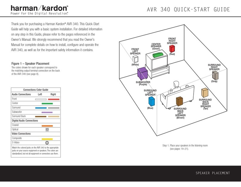
Harman Kardon AVR 1650 User manual

Harman Kardon

Harman Kardon AVR 1650 User manual

Harman Kardon AVR 139/230 User manual

Harman Kardon

Harman Kardon AVR 139/230 User manual

Harman Kardon HK3475 Instructions and recipes

Harman Kardon

Harman Kardon HK3475 Instructions and recipes

Harman Kardon AVR 8000 User manual

Harman Kardon

Harman Kardon AVR 8000 User manual

Harman Kardon AVR 130 User manual

Harman Kardon

Harman Kardon AVR 130 User manual

Harman Kardon AVR 645 User manual

Harman Kardon

Harman Kardon AVR 645 User manual

Harman Kardon AVR 100 User manual

Harman Kardon

Harman Kardon AVR 100 User manual

Harman Kardon AVR 354 User manual

Harman Kardon

Harman Kardon AVR 354 User manual

Harman Kardon AVR 145 User manual

Harman Kardon

Harman Kardon AVR 145 User manual

Harman Kardon AVR2000RDS User manual

Harman Kardon

Harman Kardon AVR2000RDS User manual

Popular Receiver manuals by other brands

Sony STR-DA3300ES - Multi Channel Av Receiver Technical bulletin

Sony

Sony STR-DA3300ES - Multi Channel Av Receiver Technical bulletin

Delphi SA10175 user guide

Delphi

Delphi SA10175 user guide

DKS 8040 microplus user manual

DKS

DKS 8040 microplus user manual

Onkyo TX-SR503 Service manual

Onkyo

Onkyo TX-SR503 Service manual

Aiwa AV-D35 Service manual

Aiwa

Aiwa AV-D35 Service manual

Onkyo TX-NR717 instruction manual

Onkyo

Onkyo TX-NR717 instruction manual

Yamaha RX-V496 Service manual

Yamaha

Yamaha RX-V496 Service manual

Pyle PLRVST400 user manual

Pyle

Pyle PLRVST400 user manual

FUTABA R6202SBW manual

FUTABA

FUTABA R6202SBW manual

CC&C BT-378 user manual

CC&C

CC&C BT-378 user manual

SVP HDR-108 manual

SVP

SVP HDR-108 manual

AJA RovoRx-HDMI Installation and operation guide

AJA

AJA RovoRx-HDMI Installation and operation guide

BFT MIME AC installation instructions

BFT

BFT MIME AC installation instructions

FaVal MERCURY S100 operating instructions

FaVal

FaVal MERCURY S100 operating instructions

Rhotheta RT-600 Light user manual

Rhotheta

Rhotheta RT-600 Light user manual

GBD DRS4331 quick start guide

GBD

GBD DRS4331 quick start guide

Farmnavigator Turtle Smart installation manual

Farmnavigator

Farmnavigator Turtle Smart installation manual

Saswell SAS2011DE user manual

Saswell

Saswell SAS2011DE user manual

manuals.online logo
manuals.online logoBrands
  • About & Mission
  • Contact us
  • Privacy Policy
  • Terms and Conditions

Copyright 2025 Manuals.Online. All Rights Reserved.