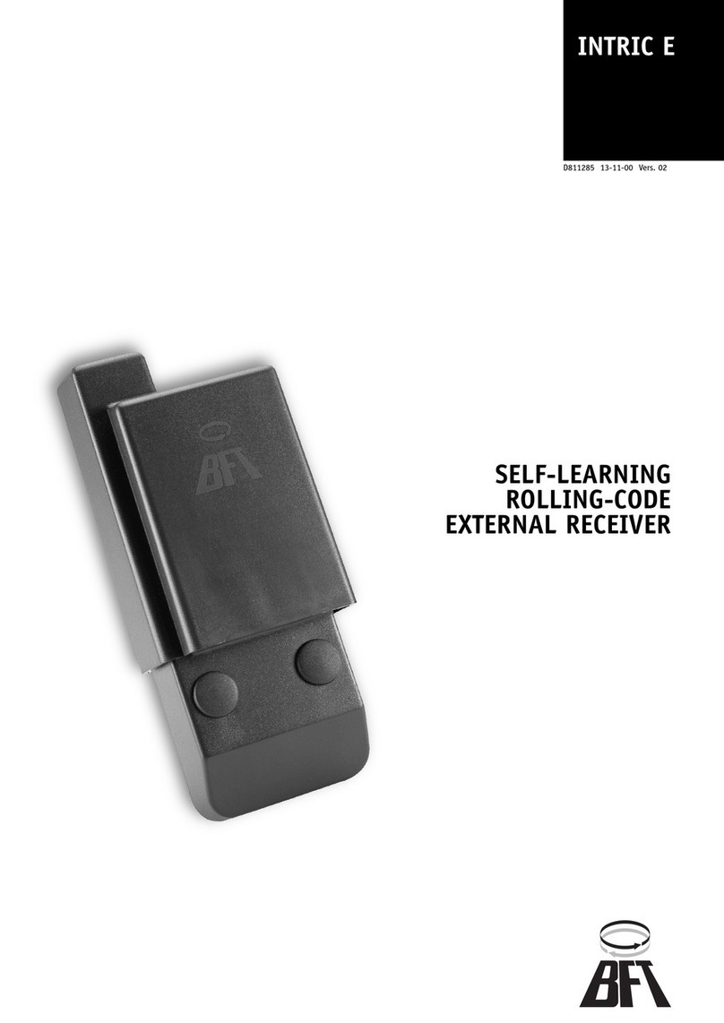
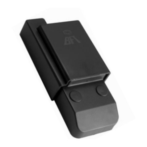
BFT MIME AC User manual

INSTALLATION INSTRUCTIONS – MOTOR CHECK
https://aros.kz
MIME
MIME AC
Attenzione! Leggere attentamente le “Avvertenze” all’interno! Caution! Read “Warnings” inside carefully! Attention! Veuillez lire attentivement les
Avertissements qui se trouvent à l’intérieur!
433 Mhz TWO-CHANNEL MINIATURE RECEIVER FOR INDOOR USE
M

42 mm 21 mm
36 mm 36 mm
A
B
1
L N
INPUTS
SUPPLY OUTPUTS
Ch1 Ch2 Ch1 Ch2
Imax = 5A
Imax = 5A
LN
1 2 3 4 5 6 7
DIMENSIONI DIMENSIONS
LED L1
L1 LED
LED L1
Pulsante P1
P1 Button
Touche P1
Ingresso comando locale ch.1 (attivo quando
connesso al 4) / Ch.1 local control input (active
when connected to 4)/ Touche commande
locale ch.1 (active si connectée sur le 4)
Ingresso comando/Locale ch.2 (attivo quando
connesso al 4) Ch.2 local control input (active
when connected to 4) / Touche commande
locale ch.2 (active si connectée sur le 4)
Ingresso alimentazione (neutro o“_”)
Supply input (neutral or“_”)
Entrée alimentation (neutre ou“_”)
Ingresso alimentazione (fase o“+”)
Supply input (phase or“ + ”)
Entrée alimentation (neutre ou“ + ”)
Comune contatti relè
Relay contact common
Commun contacts relais
Contatto n.o. uscita canale 1
Channel 1 output N.O. contact
Contact n.o. sortie canal 1
Contatto n.o. uscita canale 2
Channel 2 output N.O. contact
Contact n.o. sortie canal 2
2 - MIME AC
D812771 00550_03

C
1 2 3 4 5 6 7
C
L N
1 2 3 4 5 6 7
M
L N
COLLEGAMENT WIRING CONNEXIONS
Collegamenti per controllare 2 carichi indipendenti, quali ad esempio 2 lampadine
Wiring to check 2 independent loads, such as 2 bulbs for instance
Connexions pour contrôler 2 charges indépendantes, telles que 2 lampes
Collegamenti per controllare 1 carico indipendente, quale ad esempio 1 motore
Wiring to check 1 independent load, such as 1 motor for instance
Connexions pour contrôler 1 charge indépendante, telle que 1 moteur
Ingressi locali: 2 interruttori oppure 2 pulsanti
Local inputs: 2 switches or 2 buttons
Entrées locales: 2 interrupteurs ou 2 touches
Ingressi locali: 2 interruttori oppure 2 pulsanti
Local inputs: 2 switches or 2 buttons
Entrées locales: 2 interrupteurs ou 2 touches
2 carichi resistivi 230VAC 1250 VA Max ciascuno
2 resistive loads, 230VAC 1250 VA Max each
2 charges résistives 230V CA 1250 VA maxi chacune
Motore 230VAC asincrono monofase
Max 1250 VA @ cosφ =1 - Max 500VA @ cosφ = 0.4
230VAC asynchronous single phase motor
Max 1250 VA @ cosφ =1 - Max 500 VA @ cosφ = 0.4
Moteur 230VAC asynchrone monophasé
Maxi 1250 VA à cosφ =1 - Maxi 500 VA à cosφ = 0.4
LED L1
L1 LED
LED L1
LED L1
L1 LED
LED L1
Pulsante P1
P1 Button
Touche P1
Pulsante P1
P1 Button
Touche P1
ENGLISH FRANÇAISITALIANO
2 - MIME AC MIME AC - 3
D812771 00550_03

1
L N
INPUTS
SUPPLY OUTPUTS
Ch1 Ch2 Ch1 Ch2
Imax = 5A
Imax = 5A
LN
> 3s
1
L N
INPUTS SUPPLY
OUTPUTS
Ch1 Ch2 Ch1 Ch2
Imax = 5A
Imax = 5A
LN
1
L N
INPUTS
SUPPLY OUTPUTS
Ch1 Ch2 Ch1 Ch2
Imax = 5A
Imax = 5A
LN
X 3
1
L N
INPUTS
SUPPLY OUTPUTS
Ch1 Ch2 Ch1 Ch2
Imax = 5A
Imax = 5A
LN
X3
X1
1
L N
INPUTS
SUPPLY OUTPUTS
Ch1 Ch2 Ch1 Ch2
Imax = 5A
Imax = 5A
LN
X 3
1
L N
INPUTS
SUPPLY OUTPUTS
Ch1 Ch2 Ch1 Ch2
Imax = 5A
Imax = 5A
LN
X 1
1
L N
INPUTS
SUPPLY OUTPUTS
Ch1 Ch2 Ch1 Ch2
Imax = 5A
Imax = 5A
LN
X5
1
L N
INPUTS
SUPPLY OUTPUTS
Ch1 Ch2 Ch1 Ch2
Imax = 5A
Imax = 5A
LN
X 5
D
D1
1
L N
INPUTS
SUPPLY OUTPUTS
Ch1 Ch2 Ch1 Ch2
Imax = 5A
Imax = 5A
LN
X1
1
L N
INPUTS
SUPPLY OUTPUTS
Ch1 Ch2 Ch1 Ch2
Imax = 5A
Imax = 5A
LN
X 1
1
L N
INPUTS
SUPPLY OUTPUTS
Ch1 Ch2 Ch1 Ch2
Imax = 5A
Imax = 5A
LN
> 3s
1 2 3
4 5
1
L N
INPUTS
SUPPLY OUTPUTS
Ch1 Ch2 Ch1 Ch2
Imax = 5A
Imax = 5A
LN
6
1
L N
INPUTS
SUPPLY OUTPUTS
Ch1 Ch2 Ch1 Ch2
Imax = 5A
Imax = 5A
LN
X3
1
L N
INPUTS
SUPPLY OUTPUTS
Ch1 Ch2 Ch1 Ch2
Imax = 5A
Imax = 5A
LN
X3
7 8
CANCELLAZIONE MEMORIA MEMORY CLEARING EFFACEMENT MÉMOIRE
Dopo circa 1 secondo dal rilascio
pulsante la ricevente emetterà:
About 1 second after releasing the
button, the receiver will emit:
Environ 1 seconde après avoir lâché
la touche le récepteur émettra:
Premere il tasto della ricevente in corrispondenza
del terzo lampeggio/avviso acustico.
Press the receiver button at the third ashing/
bleep.
Appuyez sur la touche du récepteur au moment
du troisième clignotement/avis acoustique
Se la cancellazione è andata a buon
ne la ricevente emetterà :
If clearing has been successful, the
receiver will emit:
Si l’eacement a réussi le récepteur
émettra:
La cancellazione della memoria porta il dispositivo alle impostazioni di fabbrica: nessun telecomando memorizzato, modalità luce
bistabile, temporizzazioni default (vedi FIG. D5 paragrafo“PROGRAMMAZIONETIMEOUT DI FUNZIONAMENTO)
Clearing the memory restores the device to its factory settings: no remote control stored, bistable light mode, default timings (see the
OPERATION TIMEOUT PROGRAMMING paragraph)
L’eacement de la mémoire ramène le dispositif aux congurations d’usine; aucune télécommande mémorisée, mode
lumière bistable, temporisations par défaut (cf. paragraphe PROGRAMMATIION DELAI DE FONCTIONNEMENT)
PROCEDURE CONTROLLO MOTORE MOTOR PROGRAMMING PROCEDURE GESTION MOTEUR
LEGENDA KEY LÉGENDE
Premere brevemente per 3 volte
il pulsante di programmazione
Briey press the programming
button 3 times
Appuyez brièvement 3 fois sur la
touche de programmation
Mantenere premuto il pulsante
di programmazione
Keep the programming button
pressed
Appuyez sans lâcher sur la
touche de programmation
Il LED del ricevitore esegue 3 lampeggi
The receiver LED ashes 3 times
La LED du récepteur clignote 3 fois
Il LED del ricevitore esegue 1 lampeggio
The receiver LED ashes once
La LED du récepteur clignote 1 fois
Il BUZZER esegue 3 avvisi
acustici ogni 2 secondi
The BUZZER bleeps 3 times every
2 seconds
L’AVERTISSEUR SONORE retentit
3 fois toutes les 2 secondes
Il BUZZER esegue 1 avviso
acustico
The BUZZER bleeps once
L’AVERTISSEMENT SONORE
retentit une fois
4 - MIME AC
D812771 00550_03

1
L N
INPUTS
SUPPLY OUTPUTS
Ch1 Ch2 Ch1 Ch2
Imax = 5A
Imax = 5A
LN
X5
1
L N
INPUTS
SUPPLY OUTPUTS
Ch1 Ch2 Ch1 Ch2
Imax = 5A
Imax = 5A
LN
X5
1
L N
INPUTS
SUPPLY OUTPUTS
Ch1 Ch2 Ch1 Ch2
Imax = 5A
Imax = 5A
LN
X1
1
L N
INPUTS
SUPPLY OUTPUTS
Ch1 Ch2 Ch1 Ch2
Imax = 5A
Imax = 5A
LN
X1
1
L N
INPUTS
SUPPLY OUTPUTS
Ch1 Ch2 Ch1 Ch2
Imax = 5A
Imax = 5A
LN
> 3s
1 2 3
4 5
1
L N
INPUTS
SUPPLY OUTPUTS
Ch1 Ch2 Ch1 Ch2
Imax = 5A
Imax = 5A
LN
6
1
L N
INPUTS
SUPPLY OUTPUTS
Ch1 Ch2 Ch1 Ch2
Imax = 5A
Imax = 5A
LN
X5
1
L N
INPUTS
SUPPLY OUTPUTS
Ch1 Ch2 Ch1 Ch2
Imax = 5A
Imax = 5A
LN
X5
7 8
1
L N
INPUTS
SUPPLY OUTPUTS
Ch1 Ch2 Ch1 Ch2
Imax = 5A
Imax = 5A
LN
X5
1
L N
INPUTS
SUPPLY OUTPUTS
Ch1 Ch2 Ch1 Ch2
Imax = 5A
Imax = 5A
LN
X5
1
L N
INPUTS
SUPPLY OUTPUTS
Ch1 Ch2 Ch1 Ch2
Imax = 5A
Imax = 5A
LN
X1
1
L N
INPUTS
SUPPLY OUTPUTS
Ch1 Ch2 Ch1 Ch2
Imax = 5A
Imax = 5A
LN
X1
1
L N
INPUTS
SUPPLY OUTPUTS
Ch1 Ch2 Ch1 Ch2
Imax = 5A
Imax = 5A
LN
> 3s
1 2 3
4 5
1
L N
INPUTS
SUPPLY OUTPUTS
Ch1 Ch2 Ch1 Ch2
Imax = 5A
Imax = 5A
LN
6
D2
D3
T4
T1
T3
T2
7
CANCELLAZIONE MEMORIA TELECOMANDI - REMOTE CONTROL MEMORY CLEARING -
EFFACEMENT MÉMOIRE TÉLÉCOMMANDES
CANCELLAZIONE SINGOLO TELECOMANDO SINGLE REMOTE CONTROL CLEARING
EFFACEMENT TÉLÉCOMMANDE INDIVIDUELLE
ENGLISH FRANÇAISITALIANO
Dopo circa 1 secondo dal rilascio
pulsante la ricevente emetterà:
About 1 second after releasing the
button, the receiver will emit:
Environ 1 seconde après avoir lâché
la touche le récepteur émettra:
Dopo circa 1 secondo dal rilascio
pulsante la ricevente emetterà:
About 1 second after releasing the
button, the receiver will:
Environ 1 seconde après avoir lâché
la touche le récepteur émettra:
Premere il tasto della ricevente in corrispondenza
del quarto lampeggio/avviso acustico.
Press the receiver button at the fourth ashing/
bleep.
Appuyez sur la touche du récepteur au moment du
quatrième clignotement/avis acoustique
Premere il tasto della ricevente in corrispondenza
del quinto lampeggio/avviso acustico.
Press the receiver button at the fth ashing/
bleep.
Appuyez sur la touche du récepteur au moment du
cinquième clignotement/avis acoustique
Premere il tasto memorizzato del radiocomando che si vuole
cancellare
Press the button of the stored radio control that you wish to clear
Appuyez sur la touche mémorisée de la radiocommande que
vous voulez eacer
Se la cancellazione è andata a buon
ne la ricevente emetterà:
If clearing has been successful, the
receiver will emit:
Si l’eacement a réussi le récepteur
émettra:
La cancellazione della memoria telecomandi non cancella le impostazioni delle uscite.
Clearing the remote control memory does not clear the output settings.
L’eacement de la mémoire télécommandes n’eace pas les congurations des sorties.
4 - MIME AC MIME AC - 5
D812771 00550_03

1
L N
INPUTS
SUPPLY OUTPUTS
Ch1 Ch2 Ch1 Ch2
Imax = 5A
Imax = 5A
LN
X5
1
L N
INPUTS
SUPPLY OUTPUTS
Ch1 Ch2 Ch1 Ch2
Imax = 5A
Imax = 5A
LN
X 5
8 9
D4
1
L N
INPUTS
SUPPLY OUTPUTS
Ch1 Ch2 Ch1 Ch2
Imax = 5A
Imax = 5A
LN
X1
1
L N
INPUTS
SUPPLY OUTPUTS
Ch1 Ch2 Ch1 Ch2
Imax = 5A
Imax = 5A
LN
X 1
1
L N
INPUTS
SUPPLY OUTPUTS
Ch1 Ch2 Ch1 Ch2
Imax = 5A
Imax = 5A
LN
> 3s
1 2 3
1
L N
INPUTS
SUPPLY OUTPUTS
Ch1 Ch2 Ch1 Ch2
Imax = 5A
Imax = 5A
LN
X1
1
L N
INPUTS
SUPPLY OUTPUTS
Ch1 Ch2 Ch1 Ch2
Imax = 5A
Imax = 5A
LN
X 1
1
L N
INPUTS
SUPPLY OUTPUTS
Ch1 Ch2 Ch1 Ch2
Imax = 5A
Imax = 5A
LN
> 3s
4 5 6
1
L N
INPUTS
SUPPLY OUTPUTS
Ch1 Ch2 Ch1 Ch2
Imax = 5A
Imax = 5A
LN
X ...
7
1
L N
INPUTS
SUPPLY OUTPUTS
Ch1 Ch2 Ch1 Ch2
Imax = 5A
Imax = 5A
LN
X1
1
L N
INPUTS
SUPPLY OUTPUTS
Ch1 Ch2 Ch1 Ch2
Imax = 5A
Imax = 5A
LN
X 1
1
L N
INPUTS
SUPPLY OUTPUTS
Ch1 Ch2 Ch1 Ch2
Imax = 5A
Imax = 5A
LN
> 3s
8 9 10
Se la cancellazione è andata a buon
ne la ricevente emetterà:
If clearing has been successful, the
receiver will emit:
Si l’eacement a réussi le récepteur
émettra:
Continuare a mantenere premuto il pulsante di programmazione
Keep the programming button pressed
Continuez à appuyer sans lâcher sur la touche de programmation
Per concludere la selezione - To conclude the selection - Pour achever la sélection
Per cancellare un ulteriore trasmettitore ripetere il punto 7.
Per terminare la procedura attendere il time-out di 10 secondi
To clear another transmitter, repeat point 7.
To end the procedure, wait for the 10 second timeout
Pour eacer un autre émetteur répétez le point 7.
Pour achever la procédure attendez le délai de 10 secondes
SELEZIONE MODALITÀ DISPOSITIVO DEVICE MODE SELECTION SÉLECTION MODES DISPOSITIF
ATTENZIONE!VERRANNO CANCELLATI ANCHE I TELECOMANDI IN MEMORIA
WARNING! THE REMOTE CONTROLS IN THE MEMORYWILL ALSO BE CLEARED
ATTENTION! MEME LES TELECOMMANDES DANS LA MEMORE SERONT EFFACEES
Premere brevemente un numero di volte il pulsante pari alla modalità che si desidera pro-
grammare
1 pressione -> Modalità luce
2 pressioni -> Modalità motore
3 pressioni -> Ritorno a modalità luce
Il sistema segnalerà all’utente la selezione appena eettuata tramite il led con un numero
di lampeggi (veloci) e di avvisi acustici (veloci) pari alla funzione selezionata ogni 2 secondi
Briey press the button the number of times
equal to the mode you wish to program:
1 pressure -> Light mode
2 pressures -> Motor mode
3 pressures -> Return to light mode
The system will show the user the selection made
via the LED with a number of (quick) ashes and
bleeps equal to the selected function every 2
seconds.
Appuyez brièvement sur la touche un nombre de fois égal
au mode que vous voulez programmer
1 pression -> Mode lumière
2 pressions -> Mode moteur
3 pressions -> Retour à mode lumière
Le système signalera à l’utilisateur la sélection qui vient
d’être faite avec un nombre de clignotements (rapides) de
la Led et d’avis acoustiques égal à la fonction sélectionnée
toutes les 2 secondes.
6 - MIME AC
D812771 00550_03

1
L N
INPUTS
SUPPLY OUTPUTS
Ch1 Ch2 Ch1 Ch2
Imax = 5A
Imax = 5A
LN
X 1
1
L N
INPUTS
SUPPLY OUTPUTS
Ch1 Ch2 Ch1 Ch2
Imax = 5A
Imax = 5A
LN
X1
1
L N
INPUTS
SUPPLY OUTPUTS
Ch1 Ch2 Ch1 Ch2
Imax = 5A
Imax = 5A
LN
X1
1
L N
INPUTS
SUPPLY OUTPUTS
Ch1 Ch2 Ch1 Ch2
Imax = 5A
Imax = 5A
LN
X1
1
L N
INPUTS
SUPPLY OUTPUTS
Ch1 Ch2 Ch1 Ch2
Imax = 5A
Imax = 5A
LN
X1
1
L N
INPUTS
SUPPLY OUTPUTS
Ch1 Ch2 Ch1 Ch2
Imax = 5A
Imax = 5A
LN
> 3s
1
L N
INPUTS
SUPPLY OUTPUTS
Ch1 Ch2 Ch1 Ch2
Imax = 5A
Imax = 5A
LN
D5
1 2 3
4 5 6
7
1
L N
INPUTS
SUPPLY OUTPUTS
Ch1 Ch2 Ch1 Ch2
Imax = 5A
Imax = 5A
LN
> 3s
1
L N
INPUTS
SUPPLY OUTPUTS
Ch1 Ch2 Ch1 Ch2
Imax = 5A
Imax = 5A
LN
X1
1
L N
INPUTS
SUPPLY OUTPUTS
Ch1 Ch2 Ch1 Ch2
Imax = 5A
Imax = 5A
LN
X1
8 9 10
1
L N
INPUTS
SUPPLY OUTPUTS
Ch1 Ch2 Ch1 Ch2
Imax = 5A
Imax = 5A
LN
11
ENGLISH FRANÇAISITALIANO
PROGRAMMAZIONE TIMEOUT DI FUNZIONAMENTO:
OPERATION TIMEOUT PROGRAMMING:
PROGRAMMATION DÉLAI DE FONCTIONNEMENT:
Premere brevemente un numero di volte il pulsante pari alla modalità che si desidera
programmare
X 1 pressione -> 0 minuti
X 2 pressioni -> 1 minuto
...
X 60 pressioni -> 59 minuti
La ricevente esegue 3 lampeggi e 3 avvisi acustici a ogni pressione del pulsante.
Briey press the button the number of times equal to
the mode you wish to program:
X 1 pressure -> 0 minutes
X 2 pressures -> 1 minute
...
X 60 pressures -> 59 minutes
The receiver ashes and bleeps three times every
time the button is pressed.
Appuyez brièvement sur la touche un nombre de fois égal au
mode que vous voulez programmer
X 1 pression -> 0 minute
X 2 pressions -> 1 minute
...
X 60 pressions -> 59 minutes
Le récepteur clignote 3 fois et retentit 3 fois à chaque pression
de la touche.
Per memorizzare la modalità selezionate - To store the selected modes -
Pour mémoriser le
mode sélectionnez
Se il tempo non viene confermato, viene mantenuto il tempo impostato precedentemente.
If the time is not conrmed, the previously set time is maintained.
Si le temps n’est pas conrmé, le temps conguré précédemment est maintenu.
Premere brevemente un numero di volte il pulsante pari alla modalità che si desidera
programmare
X 1 pressione -> 1 secondo
X 2 pressioni -> 2 secondi
...
X 59 pressioni -> 59 secondi
La ricevente esegue 4 lampeggi e 4 avvisi acustici a ogni pressione del pulsante.
(N.B: se si tenta di impostare un tempo pari a 0 secondi, il MIME AC imposterà un
tempo di default pari a 60 secondi nella modalità LUCE e di 240 secondi nella mo-
dalità MOTORE).
6 - MIME AC MIME AC - 7
D812771 00550_03

1
L N
INPUTS
SUPPLY OUTPUTS
Ch1 Ch2 Ch1 Ch2
Imax = 5A
Imax = 5A
LN
X 2
1
L N
INPUTS
SUPPLY OUTPUTS
Ch1 Ch2 Ch1 Ch2
Imax = 5A
Imax = 5A
LN
X2
1
L N
INPUTS
SUPPLY OUTPUTS
Ch1 Ch2 Ch1 Ch2
Imax = 5A
Imax = 5A
LN
X1
1
L N
INPUTS
SUPPLY OUTPUTS
Ch1 Ch2 Ch1 Ch2
Imax = 5A
Imax = 5A
LN
X2
1
L N
INPUTS
SUPPLY OUTPUTS
Ch1 Ch2 Ch1 Ch2
Imax = 5A
Imax = 5A
LN
X1
1
L N
INPUTS
SUPPLY OUTPUTS
Ch1 Ch2 Ch1 Ch2
Imax = 5A
Imax = 5A
LN
> 3s
1
L N
INPUTS
SUPPLY OUTPUTS
Ch1 Ch2 Ch1 Ch2
Imax = 5A
Imax = 5A
LN
E1
1 2 3
4 5 6
7
1
L N
INPUTS
SUPPLY OUTPUTS
Ch1 Ch2 Ch1 Ch2
Imax = 5A
Imax = 5A
LN
> 3s
1
L N
INPUTS
SUPPLY OUTPUTS
Ch1 Ch2 Ch1 Ch2
Imax = 5A
Imax = 5A
LN
X1
1
L N
INPUTS
SUPPLY OUTPUTS
Ch1 Ch2 Ch1 Ch2
Imax = 5A
Imax = 5A
LN
X1
12 13 14
Premere brevemente un numero di volte il pulsante pari alla modalità che si
desidera programmare
1 pressione -> modo 2.1 - Passo passo
2 pressioni -> modo 2.2 - Salita/stop
3 pressioni -> modo 2.3 - Discesa/ stop
4 pressioni -> modo 2.4 - Passo passo uomo presente
5 pressioni -> modo 2.5 - Salita uomo presente
6 pressioni -> modo 2.6 - Discesa uomo presente
7 pressioni -> modo 2.7 - Stop
8 pressioni -> modo 2.8 - Salita
9 pressioni -> modo 2.9 - Discesa
10 pressioni -> ritorno a funzione 1
Il sistema segnalerà all’utente la selezione appena eettuata tramite il led con un numero di lampeggi
(veloci) e di avvisi acustici (veloci) pari alla funzione selezionata ogni 2 secondi.
PROCEDURE RADIO
- RADIO PROCEDURES - PROCÉDURES RADIO
APPRENDIMENTO DEL PRIMO TELECOMANDO O DI ULTERIORI TELECOMANDI IN MODALITÀ MOTORE:
LEARNING THE FIRST REMOTE CONTROL OR FURTHER REMOTE CONTROLS IN MOTOR MODE:
APPRENTISSAGE DE LA PREMIÈRE TÉLÉCOMMANDE OU D’ULTÉRIEURES TÉLÉCOMMANDES EN MODE MOTEUR:
Briey press the button the number of times equal to
the mode you wish to program:
X 1 pressure -> 1 second
X 2 pressures -> 2 seconds
...
X 59 pressures -> 59 seconds
The receiver ashes and bleeps four times every time
the button is pressed. (N.B.: If you try and set a time
equal to 0 seconds, the MINI RX will set a default
time equal to 60 seconds in the LIGHT mode and 240
seconds in the MOTOR mode).
Appuyez brièvement sur la touche un nombre de fois égal
au mode que vous voulez programmer
X 1 pression -> 1 seconde
X 2 pressions -> 2 secondes
...
X 59 pressions -> 59 secondes
Le récepteur clignote 4 fois et retentit 4 fois à chaque pres-
sion de la touche. (N.B: si vous tentez de congurer un temps
de 0 seconde, le MINI RX congurera un temps par défaut
de 60 secondes en mode LUMIÈRE et de 240 secondes en
mode MOTEUR).
Per memorizzare la modalità selezionate - To store the selected modes -
Pour mémoriser le mode sélectionnez
Se il tempo non viene confermato, viene mantenuto il tempo impostato precedentemente.
If the time is not conrmed, the previously set time is maintained.
Si le temps n’est pas conrmé, le temps conguré précédemment est maintenu.
8 - MIME AC
D812771 00550_03

8
1
L N
INPUTS
SUPPLY OUTPUTS
Ch1 Ch2 Ch1 Ch2
Imax = 5A
Imax = 5A
LN
X2
1
L N
INPUTS
SUPPLY OUTPUTS
Ch1 Ch2 Ch1 Ch2
Imax = 5A
Imax = 5A
LN
X2
910
T4
T1
T3
T2
11
T4
T1
T3
T2
1
L N
INPUTS
SUPPLY OUTPUTS
Ch1 Ch2 Ch1 Ch2
Imax = 5A
Imax = 5A
LN
X1
1
L N
INPUTS
SUPPLY OUTPUTS
Ch1 Ch2 Ch1 Ch2
Imax = 5A
Imax = 5A
LN
X1
12 13
Per concludere l’inserimento di un te-
lecomando attendere il timeout di pro-
grammazione che verrà segnalato con:
To nish entering a remote control,
wait for the programming timeout that
will be highlighted with:
Pour achever la saisie d’une télécom-
mande attendez le délai de program-
mation qui sera signalé par:
Premere il tasto del radiocomando che si desidera
memorizzare.
Press the radio control button you wish to store.
Appuyez sur la touche de la radiocommande que vous voulez
mémoriser
Ad avvenuta memorizzazione il
ricevitore eseguirà:
When stored, the receiver will do the
following:
Au terme de la mémorisation le
récepteur accomplira:
Per apprendere un ulteriore radiocomando (o tasto) ripetere
il punto 8.
To learn another radio control (or button) repeat point 8.
Pour apprendre une autre radiocommande (ou touche)
répétez le point 8.
ENGLISH FRANÇAISITALIANO
Briey press the button the number of times equal to the
mode you wish to program:
1 pressure -> mode 2.1 – Step by step
2 pressures -> mode 2.2 – Up/stop
3 pressures -> mode 2.3 – Down/stop
4 pressures -> mode 2.4 – Deadman step by step
5 pressures -> mode 2.5 – Deadman up
6 pressures -> mode 2.6 – Deadman down
7 pressures -> mode 2.7 – Stop
8 pressures -> mode 2.8 – Up
9 pressures -> mode 2.9 – Down
10 pressures -> return to function 1
The system will show the user the selection made via
the LED with a number of (quick) ashes and bleeps
equal to the selected function every 2 seconds.
Appuyez brièvement sur la touche un nombre de fois
égal au mode que vous voulez programmer
1 pression -> mode 2.1 - Pas à pas
2 pressions -> mode 2.2 - Montée/stop
3 pressions -> mode 2.3 - Descente/stop
4 pressions -> mode 2.4 - Pas à pas homme présent
5 pressions -> mode 2.5 - Montée homme présent
6 pressions -> mode 2.6 - Descente homme présent
7 pressions -> mode 2.7 - Stop
8 pressions -> mode 2.8 - Montée
9 pressions -> mode 2.9 - Descente
10 pressions -> Retour à fonction 1
Le système signalera à l’utilisateur la sélection qui vient
d’être faite avec un nombre de clignotements (rapides)
de la Led et d’avis acoustiques égal à la fonction sélec-
tionnée toutes les 2 secondes.
NOTA: In caso di memoria piena il ricevitore eseguirà 10 lampeggi e 10 avvisi acustici
Note:
- Tempo di funzionamento massimo versione motore 6 minuti e 59 secondi.
- Tempo di funzionamento default motore 4 minuti
NOTE: If the memory is full, the receiver will ash 10 times and 10 bleeps will be sounded
Notes:
- Max operating time for motor version 6 minutes and 59 seconds.
- Motor default operating time 4 minutes
REMARQUE: Si la mémoire est pleine le récepteur émettra 10 clignotements et 10 avis acoustiques
Remarques:
- Temps de fonctionnement maximum version moteur 6 minutes et 59 secondes.
- Temps de fonctionnement par défaut moteur 4 minutes
8 - MIME AC MIME AC - 9
D812771 00550_03

AVVERTENZE PER L’INSTALLATORE D812160_04
ENGLISH
INSTALLER WARNINGS
WARNING!Important safetyinstructions.Carefully
read and comply with all the warnings and instruc-
tionsthatcomewiththeproductasincorrectinstal-
lation can cause injury to people and animals and
damagetoproperty.Thewarningsandinstructions
giveimportantinformationregardingsafety,instal-
lation, use and maintenance. Keep hold of instruc-
tions so that you can attach them to the technical
le and keep them handy for future reference.
GENERAL SAFETY
This product has been designed and built solely for
the purpose indicated herein. Uses other than those
indicated herein might cause damage to the product
and create a hazard.
-The units making up the machine and its installation
mustmeettherequirementsofthefollowingEuropean
Directives, where applicable: 2004/108/EC, 2006/95/
EC, 99/05/EC and later amendments. For all countries
outside the EEC, it is advisable to comply with the
standards mentioned, in addition to any national
standards in force, to achieve a good level of safety.
-TheManufacturerofthisproduct (hereinafterreferred
to as the “Firm”) disclaims all responsibility resulting
from improper use or any use other than that for
which the product has been designed, as indicated
herein, as well as for failure to apply Good Practice in
the construction of entry systems (doors, gates, etc.)
and for deformation that could occur during use.
-Before commencing installation, check the product
for damage.
-Makesurethestatedtemperaturerangeis compatible
with the site in which the automated system is due to
be installed.
-Donotinstallthisproductinanexplosiveatmosphere:
the presence of ammable fumes or gas constitutes a
serious safety hazard.
-Disconnect the electricity supply before performing
any work on the system. Also disconnect buer bat-
teries, if any are connected.
-Before connecting the power supply, make sure the
product’s ratings match the mains ratings and that a
suitable residual current circuit breaker and overcur-
rentprotectiondevicehavebeen installeduplinefrom
the electrical system. Ensure that there is an automa-
tion, switch or 16A all-pole thermal magnetic circuit
breakeronthegrid toenablecompletedisconnection
in the conditions of overvoltage III category.
-Make sure that upline from the mains power supply
there is a residual current circuit breaker that trips at
no more than 0.03A as well as any other equipment
required by code.
-Make sure the earth system has been installed cor-
rectly: earth all the metal parts belonging to the entry
system (doors, gates, etc.) and all parts of the system
featuring an earth terminal.
-Only use original spare parts for any maintenance or
repairwork.TheFirmdisclaims all responsibilityforthe
correctoperation andsafety of the automatedsystem
if parts from other manufacturers are used.
-Do not make any modications to the automated
system’s components unless explicitly authorized by
the Firm.
-Instructthesystem’suseronwhatresidualrisksmaybe
encountered, on the control systems that have been
applied and on how to open the system manually in
an emergency. give the user guide to the end user.
-Dispose of packaging materials (plastic, cardboard,
polystyrene, etc.) in accordance with the provisions
of the laws in force. Keep nylon bags and polystyrene
out of reach of children.
WIRING
WARNING! For connection to the mains power supply,
use: a multicore cable with a cross-sectional area of at
least 5x1.5mm2or 4x1.5mm2when dealing with three-
phase power supplies or 3x1.5mm2for single-phase
supplies (by way of example, type H05 VV-F cable can
be used with a cross-sectional area of 4x1.5mm2). To
connect auxiliary equipment, use wires with a cross-
sectional area of at least 0.5 mm2.
- Only use pushbuttons with a capacity of 10A-250V
or more.
- Wiresmust be securedwithadditionalfasteningnear
the terminals (for example, using cable clamps) in
order to keep live parts well separated from safety
extra low voltage parts.
- Duringinstallation,thepowercablemustbestripped
toallowtheearthwiretobeconnectedtotherelevant
terminal, while leaving the live wires as short as pos-
sible. The earth wire must be the last to be pulled
taut in the event the cable’s fastening device comes
loose.
WARNING! safety extralowvoltage wires mustbekept
physically separate from low voltage wires.
Onlyqualiedpersonnel(professionalinstaller)should
be allowed to access live parts.
SCRAPPING
Materialsmustbe disposedofin accordance
with the regulations in force. Do not throw
away your discarded equipment or used
batteries with household waste. You are
responsible for taking all your waste electri-
cal and electronic equipment to a suitable
recycling centre.
Anythingthatisnotexplicitlyprovidedfor inthe
installation manual is not allowed. Proper ope-
ration can only be guaranteed if the information
given herein is complied with.The Firm shall not
be answerable for damage caused by failure to
comply with the instructions featured herein.
While we will not alter the product’s essential
features, the Firm reserves the right, at any time,
to make those changes deemed opportune to
improve the product from a technical, design or
commercialpointofview,andwillnotberequired
to update this publication accordingly.
DECLARATIONS OF CONFORMITY CAN BE FOUND
AT http://www.bft-automation.com/CE
INSTRUCTIONS FOR USE AND ASSEMBLY CAN BE
FOUND IN THE DOWNLOAD SECTION.
12 - MIME AC MIME AC - 13
D812771 00550_03
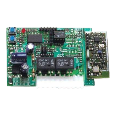
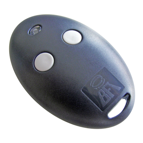
1) GENERAL INFORMATION
Two-relay two-channel receiver supplied directly from
the mains 230V 50/60Hz, extremely compact, con-
trolled by a microcontroller with decoding, remote
control self-learning, antijamming digital lter to im-
prove radio performance even further.
The rmware developed for this receiver is extremely
exible and intuitive and allows advanced functions
such as the independent change of the operating
modes for each channel.
This receiver is tted with an integrated buzzer that
allows programming without having to physically ac-
cess the board.
It uses a SAW lter to improve selectivity and suppress
out-of-band interference.
Thanks to the use of suitably sized relays, with this
receiver both lights and electrical motors can be con-
trolled.
This module is tted with a practical and ecient
low-consumption power supply unit (standby ≤0,3W)
characterized by a wide range of operating voltages
and is also protected from overvoltages at the mains
input.
Compliant with the I-ETS 300 220 and ETS 300 683 Eu-
ropean standards.
This manual will describe only the programming pro-
cedures used to control the lights. As to the program-
ming procedures to control the motor see: www.bft-
automation.com/area-download/.
2) GENERAL SAFETY
- The product is designed to operate only inside electrical
junctionboxesorwallboxes,thereforeitscontainerisnot
protected against liquid penetration but just basically
protected against the contact with solid parts (IP20). The
use in environments other than those the product has
been designed for is strictly forbidden.
- It is forbidden to open or pierce the plastic container of
the product, the parts inside it are live; do not cut or strip
the antenna wire since it is live.
- Thedevicehasnoprotectionagainstovervoltagesorshort
circuitsonoutputs,thereforeprotectionadequateto the
installedload/s(fuseor circuitbreaker)mustbeprovided.
- It is forbidden to install the receiver in SELV system
sections (i.e. bell circuits, video entry systems, 12/24V
spot lights, etc.)
- The control devices (buttons or switches) and the con-
necting cables must have isolation features suitable to
electrical systems with operating voltage no lower than
300VAC.
3) APPLICATIONS
Remote control for blinds and shutters, wireless control to
switchlightson,lightingintelligentmanagement,addition
oflightcontrolpoints,energysaving,domoticsactuator,etc
4) TECHNICAL SPECIFICATIONS
Power supply: 110-230V~ 50/60 Hz*
Capacity of the
output contacts: 5A/1250VA @
250VAC
Cosφ= 1
Output 2 relays, 5A max
Storage temperature: - 40 / + 100°C
Operating
temperature range: - 20 / + 40°C
IP rating IP 20
Max. No. of
transmitters that
can be stored
30
Built-in Rolling-Code
radio-receiver Frequency 433.92 MHz
Setting of parameters
and options
LED and BUZZER programming
button
Usable
transmitters Fixed code transmitters
ROLLING CODE
5) DIMENSIONS (FIG. A)
6) TERMINAL BOARD WIRING (FIG. B)
7)“MOTOR CONTROL” MODE FUNCTIONS
In the motor version there is a timeout (see g. D5) that
the user can program, used to stop the command recei-
ved(bybothTXandthelocalinputs)toprotectthemotor.
The relays cannot be active at the same time.
A change in activation will be preceded by both deacti-
vating for 500 ms minimum (400ms minimum).
INSTALLATION MANUAL
8)“MOTOR CONTROL” OPERATING MODE
Step by step The motor carries out the Step by Step command, that is every time the radio/wall control
code is received, it will have to comply with the UP-STOP-DOWN-STOP-UP sequence
Up/stop When the command is received, the receiver activates the relay for the set operating time,
when a second command is received it deactivates the relay.
Down/stop When the command is received, the receiver activates the down relay for the set operating
time, when a second command is received it deactivates the relay.
FRANÇAIS
14 - MIME AC
D812771 00550_03

10) RADIO PROCEDURES:
- LEARNING THE FIRST REMOTE CONTROL OR FUR-
THER REMOTE CONTROLS IN MOTOR MODE
(FIG. E1)
INSTALLATION MANUAL
Deadman
step by step When the command is received, the receiver behaves as per command 1 without executing
the stop between opening and closing. Moreover the relay is activated only for the time
during which the receiver recognizes the radio/local button code.
The relay is deactivated if the command is no longer present for 500 continuous ms or if the
maximum operating time has expired.
Deadman
up When the command is received, the receiver activates the up relay. When the radio/local
command code is no longer received for over 500 continuous ms, or the maximum operating
time is exceeded, the receiver deactivates the relay.
Deadman
down When the command is received, the receiver activates the down relay. When the radio/local
command code is no longer received for over 500 continuous ms, or the maximum operating
time is exceeded, the receiver deactivates the relay.
Stop When the command is received, the receiver deactivates the up and down relay.
Up When the command is received, the receiver activates the up relay for a maximum time equal
to the set operating time.
Down When the command is received, the receiver activates the down relay for a maximum time
equal to the set operating time.
For all the MOTOR modes, In case of a voltage drop, when the supply is restored, the minireceiver keeps the outputs
OFF.
9) PROCEDURES
- MEMORY CLEARING (FIG. D1)
- REMOTE CONTROL MEMORY CLEARING (FIG. D2)
- SINGLE REMOTE CONTROL CLEARING (FIG. D3)
- DEVICE MODE SELECTION (FIG. D4)
- OPERATION TIMEOUT PROGRAMMING
(FIG. D5)
ENGLISH
14 - MIME AC
D812771 00550_03
Bft Spa
Via Lago di Vico, 44
36015 Schio (VI)
T +39 0445 69 65 11
F +39 0445 69 65 22
www.bft.it
SPAIN
BFT GROUP ITALIBERICA DE
AUTOMATISMOS S.L.
08401 Granollers - (Barcelona)
www.bftautomatismos.com
FRANCE
AUTOMATISMES BFT FRANCE
69800 Saint Priest
www.bft-france.com
GERMANY
BFT TORANTRIEBSSYSTEME Gmb H
90522 Oberasbach
www.bft-torantriebe.de
UNITED KINGDOM
BFT AUTOMATION UK LTD
Stockport, Cheshire, SK7 5DA
www.bft.co.uk
IRELAND
BFT AUTOMATION LTD
Dublin 12
BENELUX
BFT BENELUX SA
1400 Nivelles
www.bftbenelux.be
POLAND
BFT POLSKA SP. Z O.O.
05-091 ZąBKI
www.bft.pl
CROATIA
BFT ADRIA D.O.O.
51218 Drazice (Rijeka)
www.bft.hr
PORTUGAL
BFT SA-COMERCIO DE
AUTOMATISMOS E MATERIAL DE
SEGURANCIA
3020-305 Coimbra
www.bftportugal.com
CZECH REPUBLIC
BFT CZ S.R.O.
Praha
www.bft.it
TURKEY
BFT OTOMATIK KAPI SISTEMELERI
SANAY VE
Istanbul
www.bftotomasyon.com.tr
RUSSIA
BFT RUSSIA
111020 Moscow
www.bftrus.ru
AUSTRALIA
BFT AUTOMATION AUSTRALIA
PTY LTD
Wetherill Park (Sydney)
www.bftaustralia.com.au
U.S.A.
BFT USA
Boca Raton
www.bft-usa.com
CHINA
BFT CHINA
Shanghai 200072
www.bft-china.cn
UAE
BFT Middle East FZCO
Dubai
Other manuals for MIME AC
1
Table of contents
Other BFT Receiver manuals

BFT
BFT CLONIX E Series User manual

BFT
BFT CLONIX 2E AC U-LINK 230 User manual

BFT
BFT Clonix 2E Owner's manual

BFT
BFT REO1 E User manual

BFT
BFT CLONIX Series Operating instructions

BFT
BFT INTRIC E Series User manual

BFT
BFT gsm rec 24v User manual

BFT
BFT CLONIX E Series User manual

BFT
BFT MIME AC User manual

BFT
BFT CLONIX 4 RTE User manual