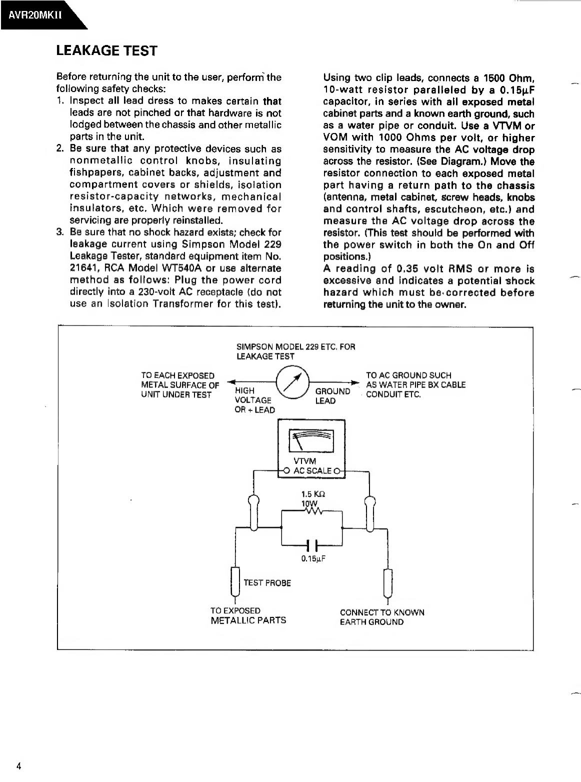
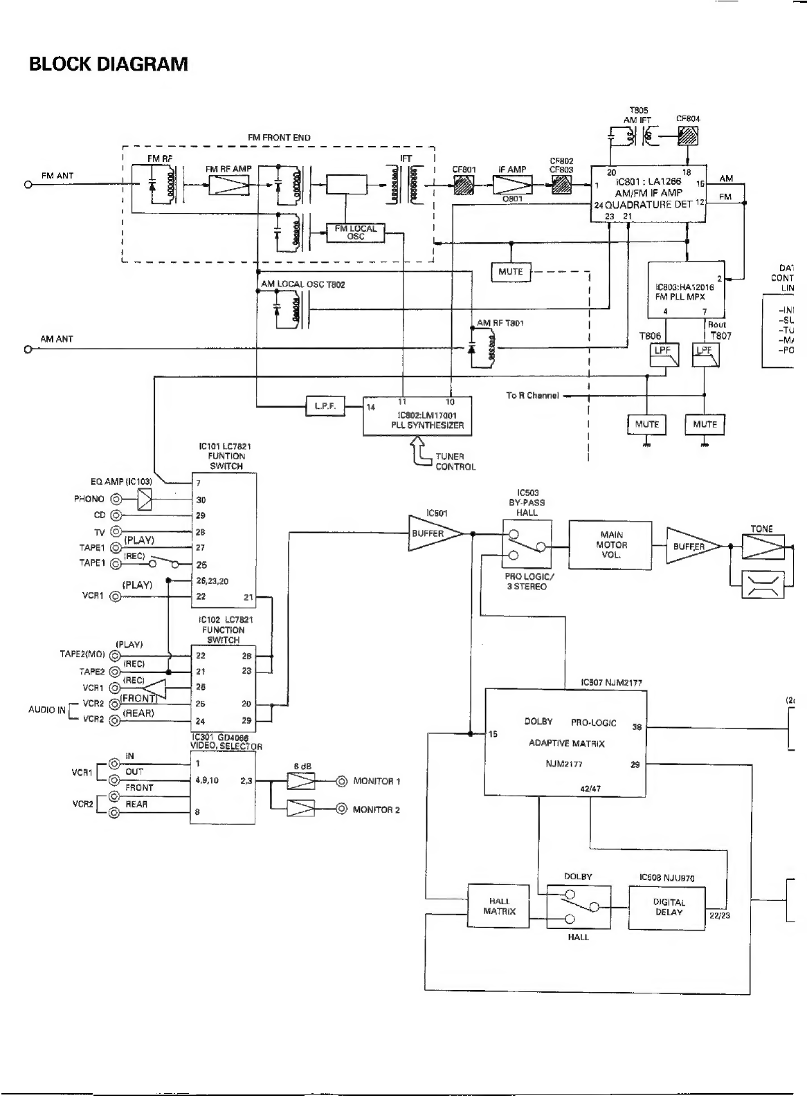
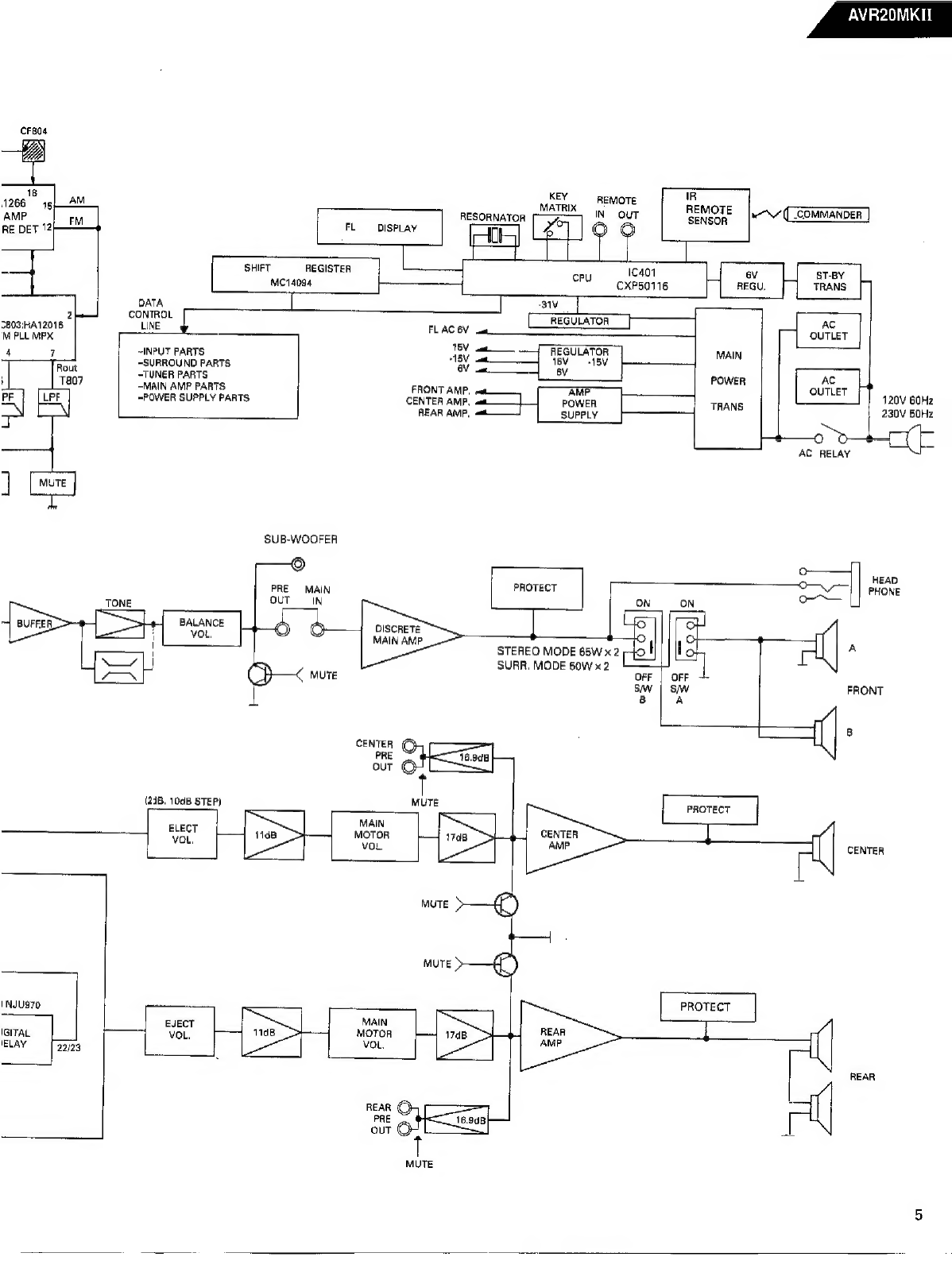
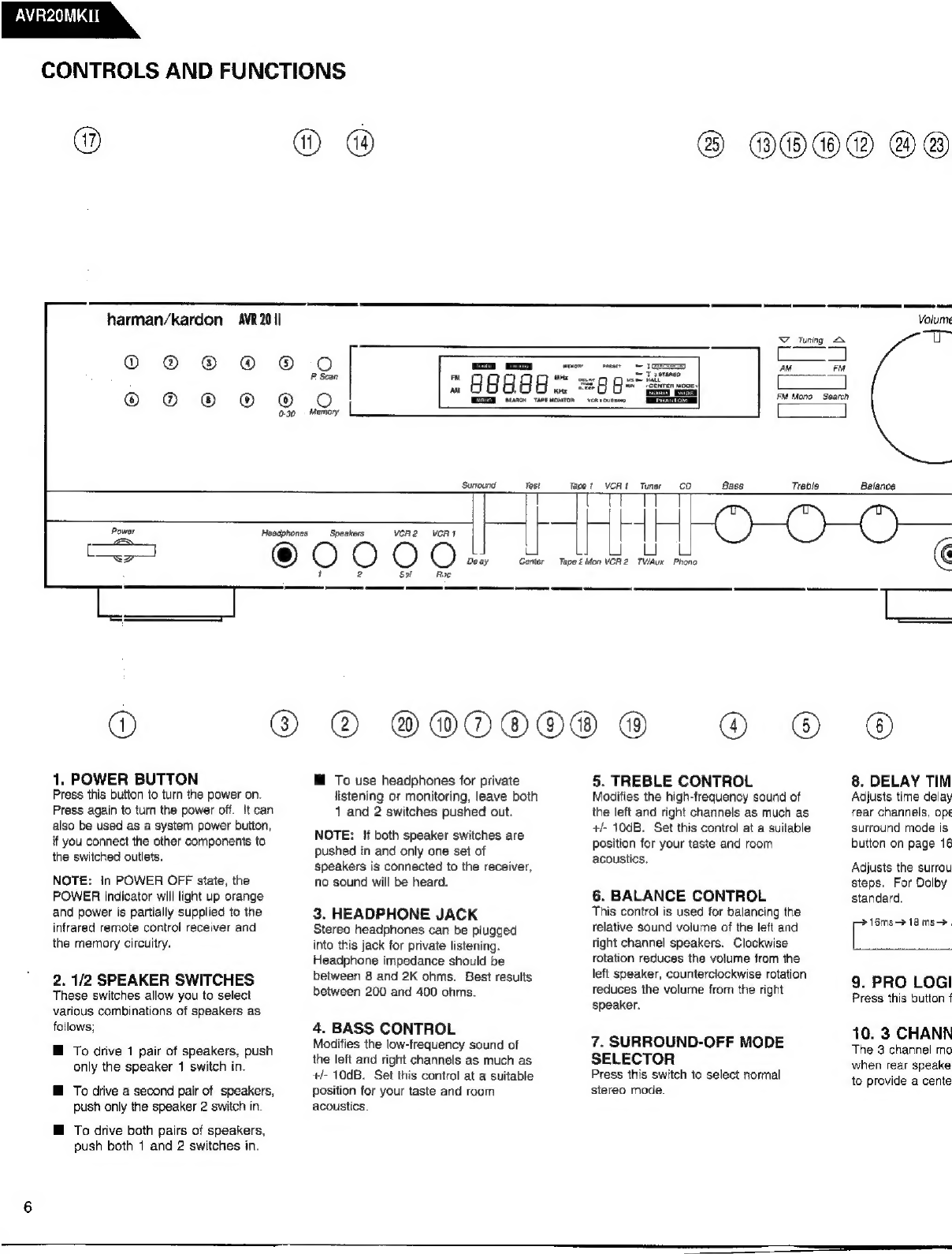
Harman Kardon AVR20MKII User manual
Other Harman Kardon Receiver manuals

Harman Kardon
Harman Kardon AVR 1700 User manual

Harman Kardon
Harman Kardon AVR 142 Installation and operation manual

Harman Kardon
Harman Kardon AVR 445 User manual

Harman Kardon
Harman Kardon AVR 1600 Service manual

Harman Kardon
Harman Kardon AVR 3500 User manual

Harman Kardon
Harman Kardon AVR 125 User manual

Harman Kardon
Harman Kardon HK 3250 User manual

Harman Kardon
Harman Kardon AVR 245 User manual

Harman Kardon
Harman Kardon HK3475 Instructions and recipes

Harman Kardon
Harman Kardon AVR 520 User manual

Harman Kardon
Harman Kardon AVR 132 User manual

Harman Kardon
Harman Kardon BRUKSANVISNING AVR 355 User manual

Harman Kardon
Harman Kardon AVR 110 User manual

Harman Kardon
Harman Kardon AVR 430 User manual

Harman Kardon
Harman Kardon NOCTURNE 210 User manual

Harman Kardon
Harman Kardon AVR 1650 User manual

Harman Kardon
Harman Kardon AVR 120 User manual

Harman Kardon
Harman Kardon AVR 630 User manual

Harman Kardon
Harman Kardon AVR 110 Instruction manual

Harman Kardon
Harman Kardon AVR 10 User manual