Harper 5400 User manual

Chipper/Shredder
R
R
R
R
5/12
& Parts Manual
1800
5400

Chipper/Shredder
R
R

Chipper/Shredder
R
R
1
Thank you for purchasing a Harper Chipper/Shredder.
As with all Harper products, the Chipper/Shredder has been developed through tough design and
testing procedures to produce a top quality machine. This manual gives assembly, operating, and
service information for the model 1800 & 5400. Please read and understand all instructional mate-
rial included with the Chipper/Shredder or its components before assembling and operating the
equipment.
A Chipper/Shredder can present hazards to an operator who follows unsafe procedures in either
the operation or maintenance of the unit. Therefore, SAFETY WARNINGS are presented at cer-
tain locations in the text.
THIS SYMBOL: SAFETY WARNING!
MEANING: Failure to understand and obey this warning may result in injury to you or others.
Whenever this symbol is used, please pay very close attention to the information presented, and
make sure you fully understand. If you do not, contact your dealer or Harper Industries, Inc. for
clarication.
SAFETY WARNING!
ALL SHIELDS AND GUARDS MUST BE IN PLACE FOR PROPER AND SAFE OPERATION
OF THIS EQUIPMENT. WHERE THEY ARE SHOWN REMOVED IN THIS MANUAL, IT IS FOR
PURPOSES OF ILLUSTRATION AND INSTRUCTION ONLY. DO NOT OPERATE THIS
EQUIPMENT UNLESS ALL SHIELDS AND GUARDS ARE IN PLACE.
Harper Industries, Inc. is continually striving to improve the design and performance of its
products. We reserve the right to make changes in specications and design without thereby
incurring any obligation relative to previously manufactured products.
© 2012 Harper Industries, Inc.
The Harper name is a registered trademark of Harper Industries, Inc. All other brand and product
names are trademarks or registered trademarks of their respective companies.

Chipper/Shredder
R
R
LIMITED WARRANTY
The Harper 1800 & 5400 Chipper/Shedder is warranted against defects in workman-
ship and materials for a period of TWELVE MONTHS from the original date of retail
purchase to the original purchaser.
Harper Industries will repair or replace, at our option, any part which our examina-
tion shows to be defective. Warranty is limited to parts, labor and ground freight
delivery of replacement parts. The user will pay freight charges for parts submitted
under this warranty.
No product or part may be returned for warranty consideration without prior
approval from Harper Industries.
This warranty does not apply to parts subjected to misuse, abuse, alteration,
improper or inadequate maintenance, or normal wear (including belts and broom).
Engines are not covered under this warranty. Refer to manufacturer’s warranty
for specic warranty information. Harper Industries, its agents or representatives,
make or imply no other warranties.
RECORDS
Date of Purchase ______ / ______ / ______
Dealer’s Name _________________________________
Dealer’s Phone _________________________________
Serial Number Machine __________________________
Serial Number Engine ___________________________
2

Chipper/Shredder
R
R
Table of Contents
OPERATOR SECTION
To the Owner or Operator............................................
Warranty Statement......................................................
Table of Contents..........................................................
Specications................................................................
Torque Chart..................................................................
General Safety Guidelines
Before Operation..............................................
During Operation..............................................
During Service..................................................
Gasoline............................................................
Guards & Shields..............................................
Safety Decals....................................................
Specic Safety Guidelines
CS-5400 PTO Powered Model.........................
CS-1800 Gas Powered Model Engine..............
Towing...............................................................
Control Identication
CS-5400 PTO Powered Model
PTO Shaft...........................................
3-Point Hitch Pins...............................
Chipper Chute....................................
Shredder Hopper................................
Jackshaft............................................
Discharge...........................................
CS-1800 Gas Powered Model
Engine Throttle Lever.........................
Engine Choke Lever...........................
Key Switch..........................................
Fuel Tank............................................
Drive Sheaves, Belts, Bearings, &
Shields................................................
Trailer Hitch........................................
Jack Stand..........................................
Chipper Chute....................................
Shredder Hopper................................
Discharge...........................................
Assembly
CS-5400 PTO Powered Model.........................
CS-1800 Gas Powered Model Engine..............
Battery................................................
Blower Attachment............................................
Discharge Grates..............................................
Operation
CS-5400 PTO Powered Model.........................
CS-1800 Gas Powered Model Engine..............
Chipping...........................................................
Shredding.........................................................
Stopping Operation
1800...................................................
5400...................................................
Adjustments
Belt Tension......................................................
Belt Adjustment
1800...................................................
5400...................................................
Service and Maintenance
Break-In Service..............................................
Lubrication.......................................................
Chipper Knives................................................
Shredder Knives..............................................
Troubleshooting...........................................................
PARTS SECTION
CS-1800
Chassis.............................................
Rotor Drive........................................
Hitch..................................................
Hopper..............................................
CS-5400
Assembly...........................................
Option - Blower Attachment..............
Rotor................................................................
1800 Decals....................................................
5400 Decals....................................................
1
2
3
4
4
5
5
5
6
6
6
7
7
7
8
8
8
8
8
8
8
8
8
8
8
8
8
8
8
8
9
9
9
10
11
12
12
13
13
13
13
14
14
15
16
16
16
17
18
22
23
24
25
26
28
31
32
33
3

Chipper/Shredder
R
R
Specications
Torque Chart
Hopper Size 34” x 21”
Chipper Plate ¾ thick machined and balanced steel plate
Chipper Knives 4 knives machined from tool steel
Chipper Chute 33”L x 13”W x 12”H
Chipper Capacity 5” maximum diameter material
Rotor 18” diameter with 36 free-swinging shredder knives
Shredder Capacity 1” to 1 ¼” maximum diameter material recommended
Grate 1 ½” grate is standard, ½” and ¾” are optional
Paint Finish Durable polyester baked paint nish with epoxy primer
The paint nish is extremely strong, and resists chipping and cracking.
Power Gas Powered Model - 18 hp. Honda engine standard
PTO Powered Model - 540 RPM from 18 to 30 HP tractor*
* Warranty may be void if used on tractors over 30 HP.
Approximate
Shipping Weight
Gas-800 lb.
PTO-600 lb.
Size In. - Lb. F-t. - Lb. N - m
No. 10-24 25-35 5-7 2.8-4.0
1/4 in. 60-80 18-20 7-9
5/16 in. 120-140 28-30 14-16
3/8 in. 340-360 64-74 24-27
1/2 in 126-150 90-100
NOTE: When tightening two or more screws
on the same part, DO NOT tighten screws
completely right away, or one at a time. To
avoid distortion, rst tighten all screws in
sequence to one-third of torque value, then
tighten to two-thirds of torque value, then
tighten to full value.
4

Chipper/Shredder
R
R
SAFETY WARNING!
Failure to understand and obey these
Safety Guidelines may result in injury to
you or others.
Before Operation
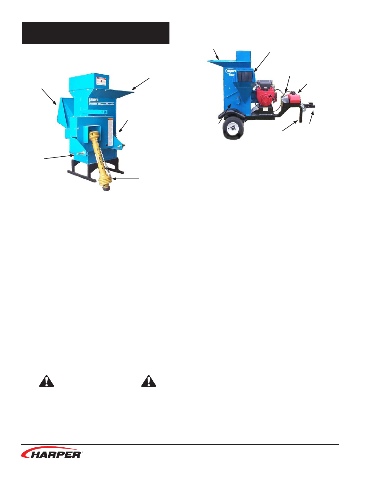
• Check feed housings for children, pets
and foreign objects before operating.
• Check to ensure that all belt guides
are in place to prevent belts from slip-
ping off the pulleys and systems from
being accidentally engaged.
During Operation
• Wear approved eye and ear protection
while operating the Chipper/Shredder.
• Keep all guards in place during opera-
tion.
• Never operate the Chipper/Shredder
with safety shields removed.
• Never allow hands, clothing or any
part of the body to enter the discharge
chute, feed chamber or near any
moving parts.
• When placing material into the ma-
chine, make certain there are no fore-
ign objects such as rocks, cans, bot-
tles or other hard materials included.
• Keep processed material from building
up in the discharge area, as this may
prohibit proper discharge and cause a
back-feed of material through the feed
opening.
• Keep the engine area clean from de-
bris and other accumulations.
• Keep all safety shields and guards in
place and in good working condition.
• Keep your face and all body parts
away from feed openings.
• Stay away from the discharge area
when machine is in operation.
• Always keep proper balance and foot-
ing, never overreach.
• If a foreign object should strike the
cutting mechanism of the machine and
cause an unusual noise or vibration,
shut the PTO engine off immediately
and allow it to come to a complete
stop. Disconnect the spark plug wire
from the spark plug, or PTO from the
power unit, and then do the following:
1. Inspect for damage.
2. Repair or replace any damaged
parts.
3. Check for and tighten any loose
bolts, nuts, fasteners or parts.
• Never attempt to move or transport
Chipper/Shredder while engine or rotor
is still operating.
• If the Chipper/Shredder should be
come clogged, shut off the engine or
PTO and allow it to come to a com-
plete stop. Disconnect the spark plug
wire or PTO shaft before clearing de-
bris.
During Service
• Replace locknuts and locking screws if
they can be tightened without feeling
resistance for several turns before
they are completely tight. Replace
them with factory-authorized parts or
their equivalent.
• If hardware is not secure, or if some
of the hardware is over-tightened,
equipment failure may result, posing
possible safety hazards.
• Use genuine factory parts or parts with
equivalent characteristics, including
type, strength and material. Failure to
do so may result in product malfunc-
tion and possible injury to the operator
or others.
• To prevent possible eye injury, always
wear SAFETY GLASSES while servic-
ing the equipment
General Safety Guidelines
5

Chipper/Shredder
R
R
Gasoline
SAFETY WARNING!
Gasoline is extremely ammable and can
be highly explosive.
Always keep a re extinguisher near the
Chipper/Shredder during operation.
• Always use an approved container for
gasoline.
• Avoid open ames or sparks while
doing maintenance or refueling.
• Never remove the fuel tank cap or add
gasoline when the engine is running or
while it is hot.
• Never ll the fuel tank indoors (fumes
can collect).
• Wipe up spilled gasoline immediately.
• Do not store gasoline in a room with
an appliance that has a pilot light, or
where electrical appliances with auto-
matic switches could cause sparks.
• Always store gasoline outside in a
safety can (a can which has a ame
arrestor and pressure relief valve in
pour spout).
• Gasoline fumes are heavy and will
sink to the lowest point, collecting and
becoming more and more hazardous.
1 part gasoline in 20 parts air will ex-
plode easily and violently.
• Never store the equipment with gaso-
line in the tank inside a building where
fumes may reach an open ame or
spark. Allow the engine to cool before
storing in any enclosure.
Guards & Shields
• Keep the equipment and attachments
in good operating condition.
• Keep all safety devices in place.
• Replace all worn, damaged, unusable,
missing or lost safety shields and
guards before operating the equip-
ment.
Safety Decals
• If safety related or instructional decals
become illegible or are removed, re-
place them immediately.
• If you replace parts that have decals
attached to them, make sure the
decals are replaced with current ver-
sions, and that decals are on the re-
placement parts before the machine is
operated again.
• New decals may be obtained from
your local Harper Dealer.
6

Chipper/Shredder
R
R
CS-5400 PTO Powered Model
• Never operate the PTO unit when trac-
tor is moving. Machine should only be
operating when setting level on ground
surface.
• To move the unit, shut the PTO off. Lift
the 3-point hitch, and then move to the
desired location.
• Keep hands, feet and clothing away
from PTO driven parts.
• Keep all guards and shields in place
during operation. Disengage PTO and
shut off the engine before removing
guards or shields.
• Never attempt to adjust, clean or lubri-
cate the machine while it is in opera-
tion.
• Operator should never wear loose
clothing when working around PTO.
• Before starting tractor, make sure that
the transmission and PTO are disen-
gaged.
• A belt between the PTO shaft and the
rotor shaft drives the cutting blades
whenever the PTO shaft is turning.
SAFETY WARNING!
Recommended tractor PTO horsepower is
18 to 30 HP. Use of tractors above 30 HP
may cause belt damage and will void war-
ranty.
SAFETY WARNING!
Cutting blade rotation cannot be con-
trolled from the Chipper/Shredder.
CS-1800 Gas Powered Model
Engine
• Be certain to provide adequate ventila-
tion if an engine must be run indoors -
exhaust fumes are dangerous.
• Periodically clean chopped material
away from engine to lessen the possi-
bility of re.
• Always keep a re extinguisher near
the Chipper/ Shredder during opera-
tion.
• Engine governor settings are pre-
set and should not be changed; any
change can damage moving parts and
void the warranty.
• Keep clothing and all body parts away
from rotating parts.
Towing
• A 2” ball is required to tow this unit.
Make sure bolts holding tongue are
secure and always use a safety chain.
• When towing, travel at speed safe for
conditions. Do not exceed 30 mph.
Always have jack in transport position.
• Tire pressure should be 60 psi. Make
sure all wheel lug nuts are tight.
SAFETY WARNING!
Gasoline is extremely ammable and can
be highly explosive. To minimize the dan-
ger:
• Always use an approved container for
gasoline.
• Do not allow open ames or sparks
while performing maintenance or
refueling.
• Never remove the fuel tank cap or add
gasoline when the engine is running or
hot.
• Refer to Engine manual for additional
information on gasoline.
Specic Safety Guidelines
7

Chipper/Shredder
R
R
\
CS-5400 PTO Powered Model
PTO Shaft - Transfers power from the tractor
to the Chipper/Shredder. Due to varia-
tions in tractor styles, the operator is
responsible for ensuring that the PTO
shaft is the correct length for a given
tractor. (See the Assembly instruc-
tions.)
3-Point Hitch Pins - Mounts the Chipper/
Shredder to the 3-Point Hitch of the
tractor.
Chipper Chute - Materials to be chipped are
fed into the chipper chute.
Shredder Hopper - Materials to be shredded
are fed into the shredder hopper.
Jackshaft – The jackshaft is connected to
the PTO shaft and used to adjust ten-
sion for drive belts.
Discharge - The area where chipped and
shredded materials are discharged.
SAFETY WARNING!
Make sure that angle of PTO shaft does
not exceed 15 degrees.
CS-1800 18 HP Gas Powered Model
Engine Throttle Lever - The throttle lever
controls engine speed and ranges
from full throttle operation to low idle
for warm up.
Engine Choke Lever - The choke lever is
used in cold starting situations. Refer
to engine manual for starting instruc-
tions.
Key Switch –The key switch is used for
starting the engine.
Fuel Tank – The fuel tank is located on the
hitch and has a 3-gal. capacity. Refer
to engine manual for fuel recommen-
dations.
Make sure vent is open before operation.
Drive Sheaves, Belts, Bearings and
Shields – All are driven from the engine.
(Not shown in photo.)
Trailer Hitch - Tow unit with a 2” ball only.
Always use a safety chain. This unit
it not designed for highway use – 30
MPH max.
Jack Stand – The jack stand should always
be in the up position when transport-
ing. When operating Chipper/ Shred-
der it should be down and locked.
Chipper Chute - Materials to be chipped are
fed into the chipper chute.
Shredder Hopper - Materials to be shredded
are fed into the shredder hopper.
Discharge - The area where chipped and
shredded materials are discharged.
Control Identication
Chipper
Chute
Chipper
Chute
Key
Switch
Jack
Stand
Fuel
Tank
3 pt.
Hitch
Pins
PTO
Shaft
Shredder
Hopper
Shredder
Hopper
Discharge Discharge Hitch
8

Chipper/Shredder
R
R
CS-5400 PTO Powered Model
1. Mount feet onto machine base.
2. Connect PTO shaft to input shaft of
machine, tighten set screws on shaft.
3. Mount 3-point hitch pins onto
Chipper/Shredder.
4. Mount Chipper/Shredder to 3-point hitch
of tractor and secure with lynch pins.
IMPORTANT: Do not connect the PTO
shaft at this time.
5. Raise the unit to the height where the
PTO shaft would be level if installed (PTO
shaft should be at shortest length).
6. Hold the PTO shaft alongside the 540
yoke on the tractor and allow for ¾”
clearance between the outer shield and
the bell housing at the Chipper/Shredder
end of the PTO shaft.
7. If the PTO shaft is too long, separate the
halves and cut the full amount of excess
length from both the male and female half.
Note: If only one end is cut from the PTO
shaft, the other end will bottom out during
operation. Cut the inner and outer shields to
compensate for the length adjustment.
8. Connect the PTO shaft to the 540 yoke on
the tractor to begin operation.
SAFETY WARNING!
• Keep pants and loose clothing away
from PTO shaft and all other shafts, pul-
leys and belts.
• Never operate the Chipper/Shredder be-
yond the suggested 540 PTO speed.
• Do not attempt to service machine while
it is in operation.
CS-1800 18 hp. Gas Powered Model
1. Mount tires and rims onto spindles.
2. Install trailer tongue to trailer using
hardware provided.
3. Mount 12-volt battery onto box on trailer
tongue and connect cables.
Battery
SAFETY WARNING!
The battery is shipped without electrolyte.
Therefore, the battery must be lled with
sulfuric acid electrolyte before the Chip-
per/Shredder can be operated.
Electrolyte:
1. Place the battery on a level surface and
remove the vent caps. If the battery has
thin plastic shields in the cell openings,
remove and discard them.
2. Fill the battery with battery grade sulfuric
acid to just above the separators.
DO NOT OVERFILL
3. Reinstall the vent caps, then charge the
battery as instructed below. AFTER
charging, check the acid level, and ll to
the bottom of the vent well openings.
DO NOT OVERFILL
Charging:
1. Make sure the vent caps included with the
battery are installed.
Assembly
9

Chipper/Shredder
R
R
2. Connect the battery to a charger accord-
ing to the manufacturer’s instructions and
charge at 10 amperes for 50 minutes, or
2-9 amperes for 2 hours (depending on
capability of the charger).
Installation:
1. Make sure the cable terminals and any
hold-down parts are clean. If the battery is
a replacement and the connectors and
hold-down parts have been used before;
clean them with a wire brush.
2. Place the battery in the box with the
terminals on the side nearest the tongue,
and secure the battery in position with
hold-down parts provided.
3. Connect the cables to the proper
terminals, connecting the UNGROUNDED
cable rst. Do not over-tighten. Apply a
commercial battery anti-corrosion material
or petroleum jelly to the terminals to
minimize corrosion.
SAFETY WARNING!
• Battery electrolyte can cause se-
vere burns if handled improperly.
Observe all poison/danger warnings
on electrolyte cartons and on the
battery.
• Wear splash-proof goggles and
protective clothing when adding
electrolyte to batteries.
• Avoid contact of electrolyte with
skin, eyes, or clothing.
• Keep batteries and electrolyte OUT
OF REACH OF CHILDREN.
• If electrolyte is spilled or splashed
on the body, IMMEDIATELY FLUSH
WITH WATER.
• If electrolyte comes into contact
with the eyes, FLUSH WITH
WATER FOR 15 MINUTES AND GET
PROMPT MEDICAL ATTENTION.
• If electrolyte is taken internally,
DRINK LARGE QUANTITIES OF
WATER OR MILK, FOLLOWED WITH
MILK OF MAGNESIA, BEATEN
EGGS, OR VEGETABLE OIL.
SAFETY WARNING!
• The battery can produce explosive
gases. Ventilate when charging or
using in an enclosed space.
• DO NOT produce sparks from cable
clamps, tools or other sources.
• DO NOT allow ames or smoking in
the vicinity of the battery.
• Shield eyes when working near the
battery.
• Keep the vent caps tight and level.
Blower Attachment
1. Remove blower and directional spout from
boxes.
2. Remove rear shaft guard and safety door
from Chipper/Shredder.
3. Mount blower attachment to Chipper/
Shredder using safety door hinge pin,
secure blower to unit using 4 - 5/16” x 3/4”
bolts and 5/16” nylock nuts.
4. Install belt shield mount tab on top bolt of
bearing using 1/2” lock nut.
10

Chipper/Shredder
R
R
5. Mount drive pulley on drum shaft. Align
pulleys and tighten to 17 ft-lb. Mount belt
on unit routing idler in center of belt.
Install belt shield using 5/16” bolts and at
washers.
6. Mount lower directional spout to blower
using 5/16” bolts and at washers.
7. Mount upper directional spout to lower
using 5/16” x 3/4” bolts, 5/16” lock nuts
and bearings. Make sure that 1/4” washer
is placed between bearing and mount tab.
8. Mount crank assembly to mount tab using
2 3/8” x 1” carriage bolts and 3/8” nylock
nuts. Place 2 3/8” at washers under each
bolt location to shim up crank assy.
NOTE: This may vary due to required
clearance for crank.
9. Mount deector spout to upper spout
using 2 5/16” x 34” truss head bolts. A
5/16” washer is used for a spacer
between deector and spout.
Discharge Grates
• The factory-installed standard dis-
charge grate has 1½” diameter holes.
• Installing a discharge grate with small-
er diameter holes can increase ne-
ness of the shredded material.
• Discharge grates with ½” and ¾” diam-
eter holes are available for the Chip
per/Shredder.
• A discharge grate with parallel bars is
available for shredding leaves or green
material.
To change discharge grates:
1. Remove the rear door hinge pin and
remove the rear safety door.
2. Remove the 6- 3/8” x 1” bolts holding the
grate in place. Remove the grate.
3. Install new grate. Make sure to install the
rounded edge of the grate to the bottom.
4. Reinstall bolts and rear safety door.
SAFETY WARNING!
• The cutting rotor is heavy and will
continue to turn even though the
operator has shut off the power
source. Do not attempt to service or
inspect the machine until you see
that the shafts have stopped turn-
ing and that there is no noise com-
ing from the machine.
• Never operate Chipper/Shredder
without ALL GUARDS in place.
Install this
end down
11

Chipper/Shredder
R
R
SAFETY WARNING!
• Obtain and wear safety glasses
when operating this machine. Do
not wear loose tting clothing. Op-
erator should always wear heavy-
duty gloves, boots, and other ar-
ticles of clothing.
• A safe operator is one who prac-
tices safety and uses good common
sense to protect him or herself from
sharp objects and branches.
• Move the Chipper/Shredder to a
clear level area outdoors before
operating.
Do not operate on uneven, paved or
other hard surfaced areas. Do not
operate in the vicinity of bystand-
ers.
• To avoid personal injury, always
keep face and body parts away from
feed openings. Never over-reach
and keep proper footing and bal-
ance.
CS-5400 PTO Powered Model
1. Obtain and wear safety goggles before
operating the Chipper/Shredder.
2. Check feed housings for children, pets
and foreign objects before operating.
3. Mount PTO Chipper/Shredder to 3-point
of tractor and connect PTO shaft to tractor
output shaft.
4. Adjust center link on tractor so that the
Chipper/Shredder is setting level at the
ground surface.
5. Move the Chipper/Shredder to a clear
level area outdoors before operating. Do
not operate on uneven, paved or other
hard surfaced areas. Do not operate in
the vicinity of bystanders.
6. Engage tractor PTO to begin operation.
CS-1800 18 HP Gas Powered Model
1. Obtain and wear safety goggles before
operating the Chipper/Shredder.
2. Check feed housings for children, pets
and foreign objects before operating.
3. Before operating, ll the tank with
gasoline. (Refer to engine manual for
further information.)
4. Make sure the vent cap on the fuel tank is
open at least a quarter of a turn. (If the
vent is completely closed the engine will
vapor lock and not run.
5. Move the Chipper/Shredder to a clear
level area outdoors before operating. Do
not operate on uneven, paved or other
hard surfaced areas. Do not operate in
the vicinity of bystanders.
6. Open throttle to half way and place the
choke lever to the full open position.
7. Turn the key switch to the start position
and release as soon as the engine starts.
DO NOT TURN THE STARTER OVER
FOR MORE THAN 10 SECONDS.
8. Once the engine is running, gradually
move the choke lever to the off position,
and allow the engine to warm up before
opening the throttle to full speed.
9. When restarting a warm engine, it should
not be necessary to use the choke lever.
If choking is necessary, open the lever
only halfway. (Refer to engine manual for
more information.)
10. Move engagement handle on machine to
begin operation.
SAFETY WARNING!
Do not exceed 30 MPH when towing the
unit. Travel at speeds that are appropriate
for conditions and always use safety
chains.
SAFETY WARNING!
Gasoline is highly ammable and can be
highly explosive. See Safety Guidelines
section for more information.
Operation
12

Chipper/Shredder
R
R
Chipping
• Select limbs that are up to 5 inches in
diameter; trim branches that will not
t into the chipper chute. Smaller
branches can be bunched and ran
through together.
• Place limb, butt end rst, into the chip-
per chute until it touches the chipper
knives.
The feed rate of the limb into the chip-
per depends on the material and
sharpness of the chipper knives.
The operator can feed the limb by
alternately inserting and retracting the
limb or continuously feeding it, so long
as it doesn’t kill the engine or the trac-
tor. By rotating the limb you can im-
prove the cutting action of the chipper.
• The chipping knives will become dull
at varying times depending on the
wood material used. Periodic sharpen-
ing of knives will be required. Refer to
the Service & Maintenance section for
sharpening instructions.
Shredding
• Feed material such as grass, leaves,
garden refuse, and branches up to
1” in diameter and 36” long into the
shredder hopper.
• Use a leaf tamper, branch or similar
object to push light material into shred-
ding chamber.
• Feed material at an even pace to
avoid plugging or lugging of the Chip-
per/Shredder. If the shredder should
become plugged, refer to the service
section of the manual before clearing
plugged material. Branches or material
that cause plugging or slow opera-
tion should be fed at a slower pace to
avoid plugging.
SAFETY WARNING!
• Never leave the machine unattend-
ed, or attempt service or inspec-
tion unless the machine has come
to a complete stop, the engine has
been shut off, and the spark plug
has been disconnected.
• On PTO units, make sure the PTO
and the tractor engine has been
shut off and the machine has come
to a complete stop.
NOTE: To avoid entanglement with material
going into the shredder hopper it is suggested
to use a throwing motion when feeding mate-
rial.
Stopping Operation
CS-1800 18 HP Gas Powered Model
1. Move the throttle lever to the slow position
and disengage manual engage lever.
2. Shut off the engine and allow the machine
to come to a complete stop.
3. If it is necessary to inspect or work on the
Chipper/Shredder, remove the spark plug
wire from the spark plug.
CS-5400 PTO Powered Model
1. Move throttle on tractor to the slow
position and disengage the PTO lever on
the tractor.
2. Shut off the tractor engine and allow the
machine to come to a complete stop.
3. If it is necessary to inspect or work on the
Chipper/Shredder, always disengage the
PTO and shut off the tractor engine before
doing so.
13

Chipper/Shredder
R
R
SAFETY WARNING!
• The cutting rotor is heavy and will
continue to turn even though the
operator has shut off the power
source. Do not attempt to service or
inspect the machine until you see
that the shafts have stopped turn-
ing and that there is no noise com-
ing from the machine.
• If the operator wants to slow the
machine faster, he can do so by
inserting a limb into the chipper
chute so that it contacts the knives
and slows the machine down.
• Never operate Chipper/Shredder
without ALL GUARDS in place.
Belt Tension
• On initial operation of the Chipper/
Shredder, the belts may shrink and
need readjustment after the rst hour
of use.
• Check the condition of drive belts be-
fore each use or after every 25 hours
of operation.
• Use only industrial V-belts. Do not use
automotive belts.
• Do not over tighten belts. Excessive
tension can cause premature bearing
and belt failure.
• Use a straightedge to check alignment
across the faces of pulleys after ad-
justing belt tension to ensure that the
belts will run true.
Belt Adjustment
CS-5400 PTO Powered Model
1. Make certain that PTO shaft is removed
from power source and un-mounted from
3-point hitch of tractor.
2. Disconnect PTO shaft from Chipper/
Shredder and remove belt guards.
3. Loosen bolts that mount the jackshaft
pillow block bearings and move the shaft
towards the frame.
4. Remove the belt. Inspect or replace with a
new belt.
5. Move shaft away from frame to tighten
belt and check to see that there is no
more than 1/4” up and down play in the
belt.
6. Snug two bolts and check pulley alignment
with a straightedge. If not aligned, loosen
one bolt and adjust. Tighten all bolts on
bearings when alignment is achieved.
Adjustments
Jackshaft
Loosen &
Adjust Here
Loosen &
Adjust Here
Rotor Shaft
14

Chipper/Shredder
R
R
CS-1800 18 HP Gas Powered Model
1. Remove belt shield.
2. Located below the manual engage lever is
a turnbuckle. Remove the cotter pin and
turnbuckle pin.
3. Turn the turnbuckle in whichever direction
is needed to acquire proper belt tension.
There should be no more than ¼” up and
down play in the belt.
4. Replace turnbuckle pin and cotter pin and
recheck adjustment. If necessary, readjust.
5. Replace belt shield.
If adjustment requires more than what is
available at the turnbuckle, then do the
following:
1. Loosen the four 3/8” x 1 1/2” bolts holding
the engine.
2. Remove the belt and inspect or replace it.
3. Reinstall belt and draw engine back until
there is ¼” up and down play in the belt.
Use a straightedge and check for proper
alignment.
4. Tighten four engine bolts and replace
safety shield.
SAFETY WARNING!
Before working on this machine, discon-
nect spark plug wire from the spark plug
and remove the positive wire from the
battery.
Belt Guide Adjustment
For proper belt operation, adjustment of
the belt guides located on the engine is
necessary.
1. Turn engine off, remove wire from spark
plug and remove belt shield.
2. Check clearance between belt guide and
belt with drive sheave engaged.
Clearance should be 1/8”.
3. If adjustment is needed, loosen the 7/16”
x 1 ¼” bolts.
4. Adjust guide until 1/8” clearance is
reached.
5. Retighten the bolts to the specied torque
ratings.
6. Replace belt shield.
Rotor Shaft
Turnbuckle
Engagement
Arm
Belt Guide
Belt Guide
15

Chipper/Shredder
R
R
SAFETY WARNING!
• Before servicing or inspecting the
Chipper/Shredder, make sure the
power source is shut off and all
moving parts have stopped.
• Disconnect the spark plug wire
from the spark plug on Gas Pow-
ered units.
On PTO Powered units, disconnect
the PTO shaft from the tractor.
• Always wear safety glasses and
protective gloves when servicing
the Chipper/Shredder.
Break-In Service
• After the rst hour of use:
• Check belts. Re-tension if needed.
• Tighten set screws on bearings.
• Check nuts, bolts and fasteners to see
that they are secure.
Lubrication
• Lubricate grease ttings after every
50 hours of use.
• There are 2 ttings on the rotor shaft
of both the Gas and PTO Powered
models.
• The PTO Powered model also has 2
ttings on the jackshaft and 2 ttings
on the PTO shaft.
SAFETY WARNING!
• Wear protective gloves whenever
handling or working near knives.
• Knives and their retaining hardware
rotate at high speed. It is essential
that they be mounted as described
in the instructions to prevent acci-
dents from ying metal.
Chipper Knives
Depending on the type of wood being fed into
the chipper, the knives eventually become
dulled, slowing chipping time and making it
harder to produce chips. It is recommended
that chipper knives be sharpened every 5 to
10 hours of use.
Removal:
1. Remove the nine 5/16” bolts that fasten
the top and bottom housings together.
2. Remove the bolts that fasten the top of the
grate and open hinged housing to access
drum housing.
3. Rotate drum so that knife is most acces-
sible through chipper chute.
Remove the two 5/16” bolts and the chip-
per knife. Repeat this step for the remain-
ing knives.
Sharpening:
• The chipper blades can be sharpened
with a bench grinder or done by a
Harper dealership.
• Avoid getting blade surface too hot to
where it changes color. This will re
move the heat-treatment and may at-
tribute to premature failure. When
grinding, use short grinding intervals
and cool in between with water.
• Remove equal amounts to keep knives
balanced. Regrind knife-edge to 35
degrees of angle. Failure to do so may
affect chipping performance.
Mounting:
1. Mount chipper knives to rotor plate with
sharpened edge facing chipper chute.
Use Grade 5 5/16” x 1” bolts that have
been treated with Loctite® or equivalent.
2. After knives are mounted, tighten bolts to
specied torque using the Standard Torque
Chart.
3. Re-assemble housing.
Service & Maintenance
16

Chipper/Shredder
R
R
Setting Clearance:
1. Remove safety shields covering the drive
pulley on the rotor shaft front.
2. Remove safety cover on rotor shaft rear
side.
3. Loosen screws on the rotor shaft pulley.
4. Loosen set screws on front and rear rotor
bearing lock collars.
5. Using a hammer and punch, tap the lock
collars opposite the direction of normal
rotation and remove.
6. Tap the end of the rotor shaft until the
necessary 1/16 to 1/8 clearance between
the knife and chipping block is obtained.
7. After clearance is set, replace lock collars
onto eccentric hub on bearings.
8. Rotate the lock collars in the direction of
the shaft rotation and set them with a
hammer and punch.
9. Using a straight edge, align rotor pulley
with the drive pulley and tighten to 17 FT
LBS. Set bushing with a punch and re-
torque.
10. Inspect and make sure all parts are
aligned and tight.
11. Close top half of drum housing, install
bolts and tighten. Replace grate pin in top
of grate assembly.
12. Make certain all bolts and fasteners are
tight and secure before replacing shields
and guards.
Shredder Knives
NOTE: The serrated shredder knives can be
rotated four times and re-sharpened.
Removal:
1. Remove the nine 5/16” bolts that fasten
the top and bottom housings together.
2. Remove the pin that fastens the top of the
grate and open hinged housing to access
drum housing.
3. Remove the #10-24 bolt and nut from the
knife shaft. Work with one shaft at a time
only; this will eliminate any confusion as
to proper spacing and alignment.
4. Remove the knife shaft, knives and
spacers, and reverse or replace desired
shredder knives.
Reversing or Replacing:
NOTE: Replace knives and spacers in the
same manner they are removed. (See Fig. 1)
This will eliminate improper balance and
misalignment of knives, which may cause
damage to the machine and void warranty.
1. Replace #10-24 bolt and nut through end
spacer and torque to the specied torque
value in the Standard Torque Chart.
2. Service all remaining knife shafts in this
manner.
3. Inspect and make sure all parts are
aligned and tight.
4. Close top half of rotor housing, install
bolts and tighten. Replace grate pin in top
of grate assembly.
5. Make certain that all bolts and fasteners
are tight and secure before operating.
NOTE: If unit is equipped with a Blower At-
tachment, you will need to remove the Blower
before reversing or replacing the shredder
knives.
17

Chipper/Shredder
R
R
Troubleshooting
Problem What to Check
Engine will not start. • Improper control settings.
• Engine may be low on fuel.
• Engine may be low on oil.
(The Honda Enine is equipped with “Oil-Alert”
automatic shut-off)
• Battery charge may be too low.
• Possible internal problems.
• Fuel tank vent may be closed.
Problem What to Check
Engine shuts off during operation. • Engine may be low on fuel.
• Engine may be low on oil.
(The Honda Engine is equipped with “Oil-Alert”
automatic shut-off)
• Air breather may be clogged.
Problem What to Check
Belts Slip • Tension adjustment.
• Load may be excessive.
• Knives may be too dull.
• Foreign material may be lodged in the chipper or
shredder housing.
• Bearings may have seized.
Problem What to Check
Belts wear rapidly, jump, catch, or
twist.
• Pulleys may not be properly aligned.
• Check with straightedge across faces of pulleys.
Problem What to Check
Chipper is hard to feed. • Discharge plugged.
• Dull chipper knives.
• Improper knife clearance.
Engine
Belts
Cutting and Discharge
18
This manual suits for next models
1
Table of contents