Harrod GFC-130 Instruction manual

HEAVY DUTY STEEL
2.5M DECORATIVE DOMED FRUIT
CAGE
ASSEMBLY AND INSTALLATION INSTRUCTIONS
PRODUCT CODE: GFC-130/132
Revision 8
INS811
If you wish to concrete your cage in place please see page 8.
For more information on our cages please follow the below link:-

PART IDENTIFICATION
PAGE 1
11 10 922 21
24
25
1
23
3
2
4
13
12
18
4
22
21
21
26
27
23
A
8
7
13
6
22
14
5
17
4
3
16
15
14
5
12 78
27
20
18
19
9
11
10
2
1
E
D
F
17
A
B
C
B
E

Introduction
Safety
Tools
Part Identification
Thank you very much for purchasing this Harrod Horticultural Decorative Domed
Fruit Cage.
To install your cage safely we recommend that you enlist the help of three or more
people. Take extra care when working on step ladders on soft ground.
1 x soft rubber mallet, 1 x 8mm spanner, 2 x 13mm spanners, 1 x 17mm spanner, 1 x 5m
tape measure, 1 x pair of scissors, 1 x ball of string, 1 x spirit level, 1 x hole former (ARC-
021)
Before constructing the fruit cage remove all protective packaging and check that all
parts listed in the pack contents list (CHK811) are present. Use the part identification
diagram on the opposite page to help you recognise the parts. You will have varying
quantities of cage parts depending on the number of units combined to make up your
specific arrangement. Each door kit, of which you will have at least one, comprises of
the parts list in the table below left.
(Optional)
PAGE 2
DOMED FRUIT CAGE ASSEMBLY INSTRUCTIONS
HEAVY-DUTY STEEL DOOR
KIT IDENTIFICATION (GDN105)
REF NO
Part Description
PART No.
1: 2 x 0.7m Horizontal Support PGG117
2: 1 x Diagonal Support PGG007
3: 2 x 1.9m Vertical Supports PGG006
4: 1 x 2.3m Door Support Upright PGG112
DOMED FRUIT CAGE
PARTS IDENTIFICATION
(GFC-130 & GFC132)
REF No PART DESCRIPTION PART No
13: 2.5m Horizontal Support PGG035
14: Three-Way Connector GDN-675
15: Four Way Connector GDN-679
16: Five Way Connector GDN-678
17: Dome Fruit Cage Finial (option 1) PGG055
18: Top Corner Plate PGG046
19: 2 Way Connector plate PGG012
21: Hex Bolt M10 x 20mm BOL342
22: M10 Washer BOL712
23: Dome Curved Roof Support PGG041
24: Ground Peg GPP001
25: Net Clip GPP005
26: Net Tie GAR914
4 : 2.3m Support Upright PGG112
NA 2m Wide Standard Sid Netting GAR070
NA Fitted Roof Net GDN-087
NA Whipping Twine TWN-294
NA Whipping Needle TWN-295
27: Cast Decorative Finial (Option 2) PGG022
20: 4 Way Connector plate PGG013
12: 4 x Foot Plate And Clamp GDN-108
HEAVY-DUTY STEEL DOOR
ASSEMBLY PACK (GDN116)
REF NO
Part Description
PART No.
5: 4 x Two-Way Connector GDN-676
6: 1 x T-Joint PGG005
7: 1 x Catch and Fixings GDN-809
8: 2 x Hinge and Fixings GDN-808
9: 2 x Hex Bolts M8 x 45mm GPP510
10: 4 x Plastic Washers M8 GPP710
11: 2 x Nylock Nuts M8 GPP500
12: 1 x Foot Plate and Clamp GDN-108
Note: A 3mm allen key is provided
with GDN-809 for assembly of GDN-809
and GDN-808

DOMED FRUIT CAGE ASSEMBLY INSTRUCTIONS
PAGE 3
1: After reading the introduction & checking
to make sure that all the required parts are
accounted for within your pack. Lay out on
the ground in the desired arrangement
using all 2.5m horizontal support bars
(Ref.13), all the connector plates
(ref:18,19,20) and all three, four 7 five way
connectors (ref : 14,15,16).
2: Decide where the door(s)
should go (see step 9) and slide
a T-Joint (ref:6) onto the
appropriate horizontal bar(s)
(ref:13). Ensure that the
orientation of the parts is as
shown, with the threaded holes
facing upwards and the locking
bolt on the T-joint facing into the
cage.
3: Using the correct connector
(ref: 14,15,16) for the joint in
question, connect the 2.5m
horizontal bars (ref:13) together
to form a framework of bars
which represents the roof of
your cage (in plan form) on the
ground. The soft mallet may be
needed to help slide the bars
together.
4: Check that you are happy
with the positioning of the
framework with your plot. Then
using a corner connector plate
(ref:18) make absolutely sure
the joints square as the
ultimate success of the
assembly relies upon this.
5: Using string tied to the ground
pegs (ref:24), mark out the plan
of the cage on the ground.
Where ever the string cross this
accurately mars the intended
position of an upright (ref :4).
6: Ensure that the marking
string is pulled tight and
accurately follows the
framework of horizontal bars
which act as a template. Check
once more that all is square as
described in step 4.
7: When more than two
horizontal bars come together,
it is essential to mark which
side of the string the uprights
will be located. Ground pegs
(ref:24) can be used for this.

PAGE 4
DOME FRUIT CAGE ASSEMBLY INSTRUCTIONS
8: Once all of the marking out is complete, carefully dismantle the horizontal bar framework
leaving connected only bars that can exist as a complete square unit (see step 13 for reference).
Note that the threaded holes in the horizontal bars always face upwards.
9: Your site should be laid out in a
similar way shown in (fig1). If
your site slopes, level the strings
with the aid of a spirit level.
Position the door on the lowest
side of the cage if possible to
ensure that all of the uprights
(ref:4) can enter the ground at
least the required distance of
32.5cm.
10: With the aid of a mallet and a stake,
carefully create appropriately sized holes
in the ground about 32.5cm deep to
receive the uprights (ref:4). The uprights
can be concreted if required but do not set
until the steel framework is fully
assembled and levelled.
11: Place the uprights (ref:4) into the holes and at the
same time slide on the foot plates (ref:12) as shown in
(fig 2). The uprights should be pushed into the ground
approximately 30cm at this point.
13: Your site should now look something like
shown in (fig 4) - depending on your own
particular cage configuration. Check the
uprights are vertical with the aid of a spirit level.
14: Locate the door support upright(s) (ref:4) such
that the gap between it and the upright door will
hinge is 77cm between inside faces (fig 5).
15. Slide the flat latch block (ref:7) onto
the door supporting upright and tighten
loosely as shown in (fig 6). Position the
T-joint along the horizontal bar to line up
with the door support upright.
fig 5
fig 5
fig1
fig2
770mm
fig 4fig 4
12. Before attaching the roof unit to
the uprights ensure that two hinge
parts (Ref.8) are slid onto the
hinging upright as shown in (fig 3).
Attach the fixings but at this stage
do not fully tighten. Ensure the pivot
axis is towards the outside of the
cage for a door that opens
outwards.
fig3
fig 6fig 6

DOME FRUIT CAGE ASSEMBLY INSTRUCTIONS
PAGE 5
17: At all horizontal bar
joins, bolt (ref:21,22) the
appropriate connector
plate (ref:18,19,20) as in
the example shown in (fig
7) using a 17mm spanner.
18: Your cage should now in
essence resemble (fig8), with all
the horizontal bars and connector
plates in place. On the side(s) of
the cage that the door(s) are
located measure from the ground
to top face of the horizontal bar.
With a soft mallet, tap the uprights
into the ground until this
measurement is 2 metres. Check
that the door support upright (ref:4)
is vertical and then tighten the bolt
with a 13mm spanner.
20: Using two 13mm spanners lock the foot plates (ref :12) in
place on the door support upright and the hinge by tightening the
M8 bolt. This prevents the uprights sinking. After this level out all
the horizontal bars using a spirit level and soft mallet. Lock off all
remaining foot plate clamps once this is done (fig10).
21: Take the connection node/finial (ref 17 or 27 depending
on choice) and insert the curved roof bar with the hole 3.5cm
from the end, and bolt together using an M10 bolt and
Washer (ref 21, 22) in place with the aid of a 17mm spanner
(fig 11). Assemble as many roof units as required for the
constructed framework and place on the outside of the cage.
Then place a fitted roof net over each unit.
fig 7fig 7
fig8
fig 10fig 10
fig 11fig 11
IMPORTANT NOTE:
Orientation of the curve bars is important as the holes are
different distances from the ends.
16: Locate the first square unit into the
tops of the uprights and the support
upright.
Locate any other complete square
horizontal bar units in the same way
making sure all threaded holes on the
horizontals are facing upwards.
19. The door frame(s) can be assembled with the
diagram on page 2 to assist you. Before inserting
the connectors ensure the hinge/latch blocks are
inserted on the vertical bars as shown in (fig9).
The hinge blocks must be in the same orientation as
that on the door hinging upright and the flat of the
catch blocks must face each other.
fig9
Left hand side
of door
Right hand side
of door

PAGE 6
DOMED FRUIT CAGE ASSEMBLY INSTRUCTIONS
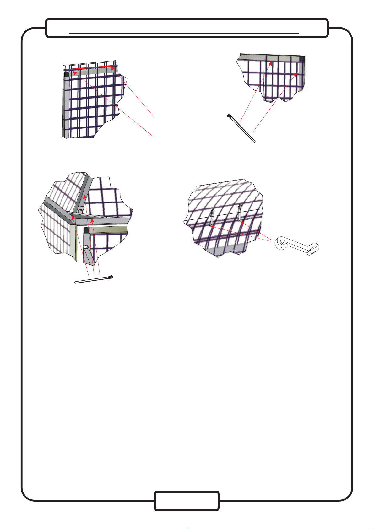
26: To fix the 2m wide side
netting, start by cutting to
allow the net to wrap around
the door support upright. This
will allow the top edge of the
net to run along the top edge
of the horizontal support bars.
27: Wrap the cut section of the side
net around the door support upright
as described in step 24. Tie in place
using net ties ( ref :26) at the top and
the bottom of the upright and a couple
equally spaced in between. Secure
the top of the net along the horizontal
bars using net ties (approx four for
every 2.5m length).
28: Continue to unroll the side
netting all the way round the
perimeter of your cage, keeping it
as taught as possible, securing as
step 25. When corners are
encountered snip the bottom few
cms flush with the ground to allow
the net to neatly fold.
29: To finish the side net and to cover the
door, unroll about 30cm past the door and
cut vertically.
30: Fold the side net around
the catch side of the door and
hold securely with several
equally spaced net clips
(ref:25). A small cut can be
made in the net to allow the
catch to protrude cleanly.
22: Slide the fitted roof net down over
the finial and align the seams with the
curved bars. Using net ties (ref :26)
secure the net around the base of the
finial and also around the curved bars.
Trim off the ends of the ties and also
any untidy stray netting.
With the aid of at least three people lift
the unit(s) into place .
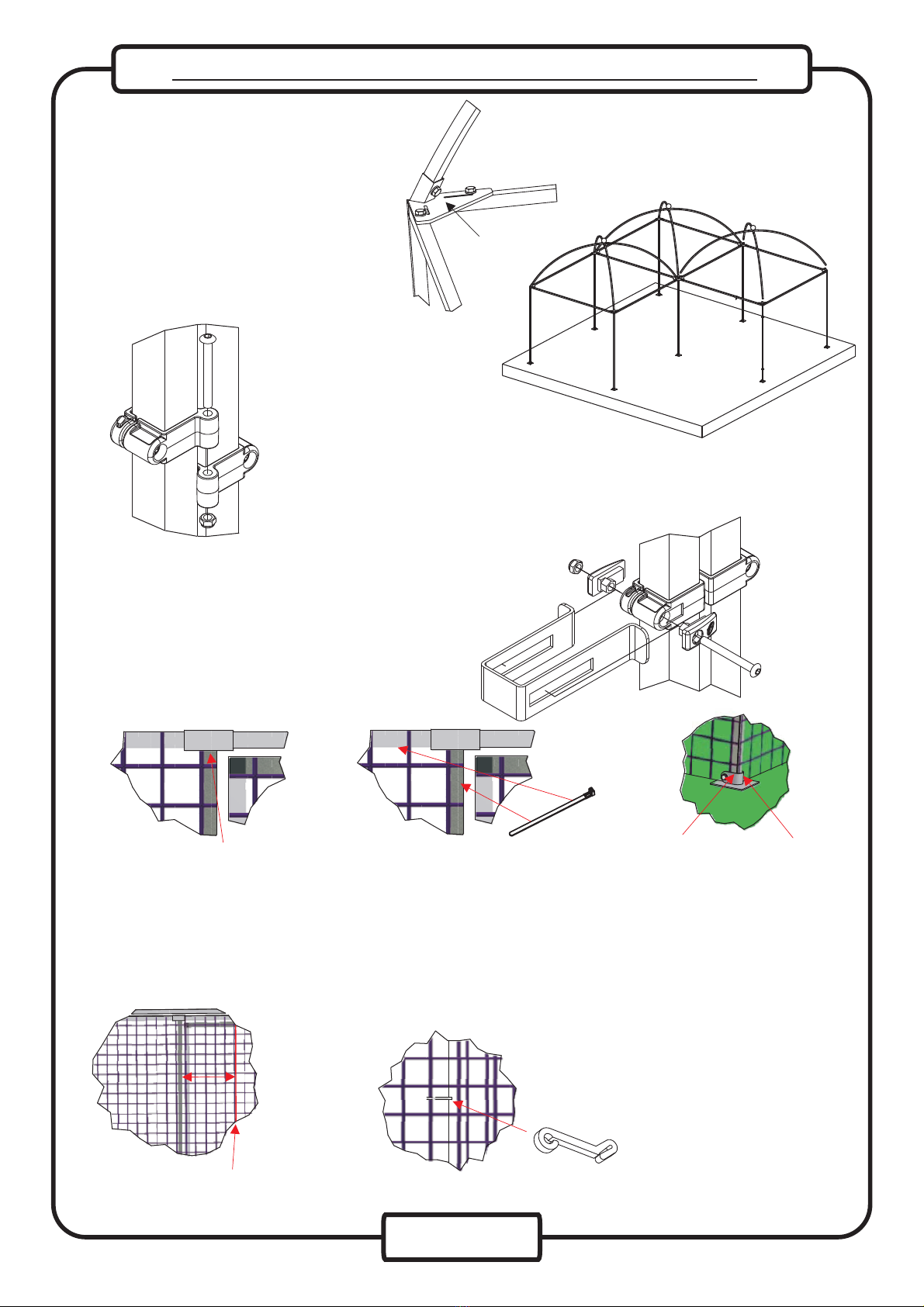
23: Bolt (ref 21,22) the curved roof
supports (ref 24) onto the connector
plate (ref:18,19,20). Tighten the bolts
using a 17mm spanner (fig 10).
fig 12fig 12
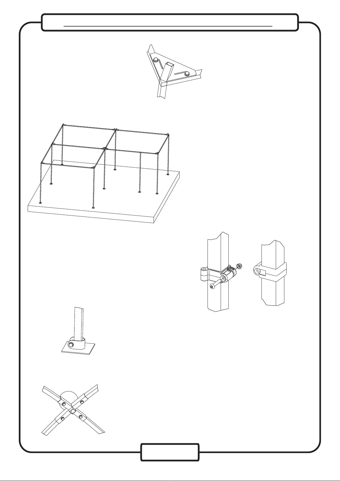
24. Place the assembled door frame in position and secure in by
joining the hinge blocks (Ref.8) as shown (fig 13) and tightening the
bolts with the 3mm allen key supplied and an 8mm spanner. Note as
the hinge blocks must spin on each other do not over tightening the
long bolt/nut through the bosses.
fig 13fig 13
25. Secure the latch in place by sliding it over
the latch block and inserting the latch inserts
as shown (fig 14). Tighten the bolts with the
3mm allen key supplied to hold in place. Note
the latch should not be over-tightened as it
must slide freely. Note the latch has one
longer side and this must be positioned on the
side you wish to open the door.
fig 14fig 14

PAGE 7
DOME FRUIT CAGE ASSEMBLY INSTRUCTIONS
34: With the whipping needle loaded with twine, tie the end of the twine through the slot in the appropriate
connector plate. Then feed the needle around the horizontal bar and through the net to neatly tie in the
nets. Finally tie off the twine through a slot in the opposing connector plate. When you are completely
happy with the result, remove all the net clips (ref :25) and trim off any untidy net edges with a pair of
scissors.
33: Load the whipping needle with the whipping twine supplied by first tying one end of the twine into a loop
over the spine in the centre of the needle. Pull the twine to the blunt end of the needle and turn the needle.
Wrap the twine around the central spine and back under the blunt end of the needle. Continue to wind the
twine onto the needle stopping just before the needle becomes to large to fit through the mesh of the fruit
cage. (For images of this please see page 8).
35: Walk around the perimeter of your cage and insert the ground pegs (ref:24) approximately three per
metre to secure the bottom of the side net. Check that the top edge of the side net lines up with the top edge
of the horizontal bars, trimming where necessary. Tie in the sides of the roof net(s) to the horizontal bars
and side net by using the twine and whipping needle, again trimming where necessary. Net clips (ref:25)
can be used to aid in this process.
36: Finally, if you are happy with the fit of the nets, with scissors or side cutters trim off the ends of the net
ties. You may wish to also whip the roof nets to the curved bars. Your cage is now finished - Happy Growing!
fig 15fig 15 fig 16fig 16
32: Using net ties (ref:26) passed through the slots provided in the corner connector plates secure the
fitted roof net(s)(fig15). Then using more net ties (approximately 1 every 40cm) work your way up the
curved roof support bars (ref:23) and secure the net to the curved bars along the net’s seams (fig16).
Where two roof nets meet, pull one of the net’s edges over and under a horizontal bar and secure to itself
with net clips (ref:25). Do not pull the net too tight or it will not follow the curved roof bars. Next pull the
adjoining net’s edge under the horizontal bar and secure to the underside of the other net panel. Again do
not pull the net too tight or it will not follow the form of the curved roof bars.
31: Trim the net level
with the top of the
door. Any side net
sticking up above the
top edge of the 2.5m
horizontal bars
around the perimeter
of the cage can also
be trimmed. Secure
the net to the door
using ties (ref :26).

PAGE 8
DOME FRUIT CAGE ASSEMBLY INSTRUCTIONS
0.15m 0.15m
0.15m x 0.15m holes can be
dug to the 32.5cm required
depth at the marked upright
locations.
Once the frame is assembled holes can be backfilled with dry mix post-crete. When
concreting your uprights in place leave some space at the top where soil can be placed over
the set concrete.
Set the uprights level in the dry mix post-crete by bracing with 45 degree wooden stakes. G-
clamps can be used to secure the braces to the uprights. When satisfied that the uprights are
vertical, soak the post-crete with water as instructed.
Ready made post-crete is available from DIY stores.
Ground
Concreting your Cage
In most cases uprights will not require concreting in place. However if you require extra
rigidity you may prefer to secure the uprights with concrete.
Loading the Whipping Needle
This manual suits for next models
1
Table of contents
Other Harrod Lawn And Garden Equipment manuals