Hart Scientific 7011 User manual

Model 7011
Temperature Bath
User Manual
Rev. 881801

© Copyright,1995 All rights reserved
Hart Scientific
799 E Utah Valley Drive
American Fork, Utah 84003
Telephone (801) 763-1600 • Fax (801) 763-1010
http://www.hartscientific.com

c
WARNING
To ensure the safety of operating personnel, and to avoid damage to this unit:
DO NOT operate this unit without a properly grounded, properly polarized power cord.
DO NOT connect this unit to a non-grounded, non-polarized outlet.
DO use a ground fault interrupt device.
WARNING
EXTREMELY COLD TEMPERATURES PRESENT
in this equipment.
FREEZER BURNS AND FROSTBITE
may result if personnel fail to observe safety precautions.
WARNING
HIGH TEMPERATURES PRESENT
in this equipment.
FIRES AND SEVERE BURNS
may result if personnel fail to observe safety precautions.
WARNING
Fluids used in this bath may produce
NOXIOUS OR TOXIC FUMES
under certain circumstances.
Consult the fluid manufacturer’s MSDS (Material Safety Data Sheet).
PROPER VENTILATION AND
SAFETY PRECAUTIONS MUST BE OBSERVED.

Table of Contents
1 Introduction. . . . . . . . . . . . . . . . . . . . . . 9
2 Specifications and Environmental Conditions . . 11
2.1 Specifications . . . . . . . . . . . . . . . . . . . . . . 11
2.2 Environmental Conditions . . . . . . . . . . . . . . . . 11
2.3 Warranty. . . . . . . . . . . . . . . . . . . . . . . . . 12
3 Safety Guidelines . . . . . . . . . . . . . . . . . . 13
4 Quick Start . . . . . . . . . . . . . . . . . . . . . 15
4.1 Unpacking . . . . . . . . . . . . . . . . . . . . . . . . 15
4.2 Set Up . . . . . . . . . . . . . . . . . . . . . . . . . . 15
4.3 Power . . . . . . . . . . . . . . . . . . . . . . . . . . 16
4.4 Setting the Temperature. . . . . . . . . . . . . . . . . 16
5 Installation. . . . . . . . . . . . . . . . . . . . . . 19
5.1 Bath Environment . . . . . . . . . . . . . . . . . . . . 19
5.2 “Dry-out” Period . . . . . . . . . . . . . . . . . . . . . 19
5.3 Bath Preparation and Filling. . . . . . . . . . . . . . . 19
5.4 Probe . . . . . . . . . . . . . . . . . . . . . . . . . . 20
5.5 Power . . . . . . . . . . . . . . . . . . . . . . . . . . 20
6 Bath Use. . . . . . . . . . . . . . . . . . . . . . . 21
6.1 General . . . . . . . . . . . . . . . . . . . . . . . . . 21
6.2 Comparison Calibration . . . . . . . . . . . . . . . . . 21
6.3 Calibration of Multiple Probes . . . . . . . . . . . . . . 22
7 Parts and Controls . . . . . . . . . . . . . . . . . 23
7.1 Front Control Panel . . . . . . . . . . . . . . . . . . . 23
7.2 Side Panel. . . . . . . . . . . . . . . . . . . . . . . . 24
7.3 Back Panel . . . . . . . . . . . . . . . . . . . . . . . 25
7.4 Lid . . . . . . . . . . . . . . . . . . . . . . . . . . . . 26
8 General Operation . . . . . . . . . . . . . . . . . 29
8.1 Bath Fluid . . . . . . . . . . . . . . . . . . . . . . . . 29
8.1.1 Temperature Range. . . . . . . . . . . . . . . . . . . . . . . 29
8.1.2 Viscosity. . . . . . . . . . . . . . . . . . . . . . . . . . . . . 29
8.1.3 Specific Heat . . . . . . . . . . . . . . . . . . . . . . . . . . 29
8.1.4 Thermal Conductivity . . . . . . . . . . . . . . . . . . . . . . 30
8.1.5 Thermal Expansion . . . . . . . . . . . . . . . . . . . . . . . 30
8.1.6 Electrical Resistivity. . . . . . . . . . . . . . . . . . . . . . . 30
8.1.7 Safety . . . . . . . . . . . . . . . . . . . . . . . . . . . . . . 30
8.1.8 Fluid Lifetime . . . . . . . . . . . . . . . . . . . . . . . . . . 31
v

8.1.9 Cost . . . . . . . . . . . . . . . . . . . . . . . . . . . . . . . 31
8.1.10 Commonly Used Fluids . . . . . . . . . . . . . . . . . . . . . 31
8.1.10.1 Water. . . . . . . . . . . . . . . . . . . . . . . . . 31
8.1.10.2 Ethylene Glycol. . . . . . . . . . . . . . . . . . . . 31
8.1.10.3 Methanol . . . . . . . . . . . . . . . . . . . . . . . 31
8.1.10.4 Mineral Oil . . . . . . . . . . . . . . . . . . . . . . 31
8.1.10.5 Silicone oil . . . . . . . . . . . . . . . . . . . . . . 32
8.1.11 Fluid Characteristics Charts. . . . . . . . . . . . . . . . . . . 32
8.1.11.1 Limitations and Disclaimer . . . . . . . . . . . . . . 32
8.1.11.2 About the Graph . . . . . . . . . . . . . . . . . . . 32
8.2 Stirring. . . . . . . . . . . . . . . . . . . . . . . . . . 35
8.3 Power . . . . . . . . . . . . . . . . . . . . . . . . . . 35
8.4 Heater . . . . . . . . . . . . . . . . . . . . . . . . . . 35
8.5 Cooling . . . . . . . . . . . . . . . . . . . . . . . . . 35
8.6 Temperature Controller . . . . . . . . . . . . . . . . . 36
9 Controller Operation . . . . . . . . . . . . . . . . 37
9.1 Bath Temperature . . . . . . . . . . . . . . . . . . . . 37
9.2 Reset Cut-out . . . . . . . . . . . . . . . . . . . . . . 37
9.3 Temperature Set-point. . . . . . . . . . . . . . . . . . 39
9.3.1 Programmable Set-points. . . . . . . . . . . . . . . . . . . . 39
9.3.2 Set-point Value . . . . . . . . . . . . . . . . . . . . . . . . . 39
9.3.3 Set-point Vernier . . . . . . . . . . . . . . . . . . . . . . . . 40
9.4 Temperature Scale Units . . . . . . . . . . . . . . . . 40
9.5 Secondary Menu . . . . . . . . . . . . . . . . . . . . 41
9.6 Heater Power . . . . . . . . . . . . . . . . . . . . . . 41
9.7 Proportional Band . . . . . . . . . . . . . . . . . . . . 42
9.8 Cut-out. . . . . . . . . . . . . . . . . . . . . . . . . . 44
9.9 Controller Configuration . . . . . . . . . . . . . . . . . 45
9.10 Probe Parameters Menu . . . . . . . . . . . . . . . . 45
9.10.1 DO . . . . . . . . . . . . . . . . . . . . . . . . . . . . . . . 45
9.10.2 DG . . . . . . . . . . . . . . . . . . . . . . . . . . . . . . . 45
9.11 Operating Parameters. . . . . . . . . . . . . . . . . . 45
9.11.1 Cut-out Reset Mode. . . . . . . . . . . . . . . . . . . . . . . 46
9.12 Calibration Parameters . . . . . . . . . . . . . . . . . 46
9.12.1 CTO. . . . . . . . . . . . . . . . . . . . . . . . . . . . . . . 46
9.12.2 H and L . . . . . . . . . . . . . . . . . . . . . . . . . . . . . 47
10 Bath Calibration. . . . . . . . . . . . . . . . . . . 49
10.1 Calibration Points . . . . . . . . . . . . . . . . . . . . 49
10.2 Measuring the Set-point Error. . . . . . . . . . . . . . 49
10.3 Computing DO and DG . . . . . . . . . . . . . . . . . 49
10.4 Calibration Example. . . . . . . . . . . . . . . . . . . 51
11 Maintenance. . . . . . . . . . . . . . . . . . . . . 53
11.1 Draining the Bath . . . . . . . . . . . . . . . . . . . . 54
12 Charging Instructions . . . . . . . . . . . . . . . 55
12.1 Preparation . . . . . . . . . . . . . . . . . . . . . . . 55
vi

12.2 Charging. . . . . . . . . . . . . . . . . . . . . . . . . 55
13 Troubleshooting . . . . . . . . . . . . . . . . . . 57
13.1 Troubleshooting . . . . . . . . . . . . . . . . . . . . . 57
13.1.1 The heater indicator LED stays red but the temperature
does not increase . . . . . . . . . . . . . . . . . . . . . . . . 57
13.1.2 The controller display flashes “CUT-OUT” and the heater
does not operate . . . . . . . . . . . . . . . . . . . . . . . . 57
13.1.3 The display flashes “CUT-OUT” and an incorrect
process temperature . . . . . . . . . . . . . . . . . . . . . . 58
13.1.4 The displayed process temperature is in error and the
controller remains in the cooling or the heating state at
any set-point value . . . . . . . . . . . . . . . . . . . . . . . 58
13.1.5 The controller controls or attempts to control at an
inaccurate temperature . . . . . . . . . . . . . . . . . . . . . 58
13.1.6 The controller shows that the output power is steady
but the process temperature is unstable . . . . . . . . . . . . 59
13.1.7 The controller alternately heats for a while then cools . . . . . 59
13.1.8 The controller erratically heats then cools, control is unstable . 59
13.1.9 The bath does not achieve low temperatures. . . . . . . . . . 59
13.2 Wiring Diagram . . . . . . . . . . . . . . . . . . . . . 60
vii

viii
Figures and Tables
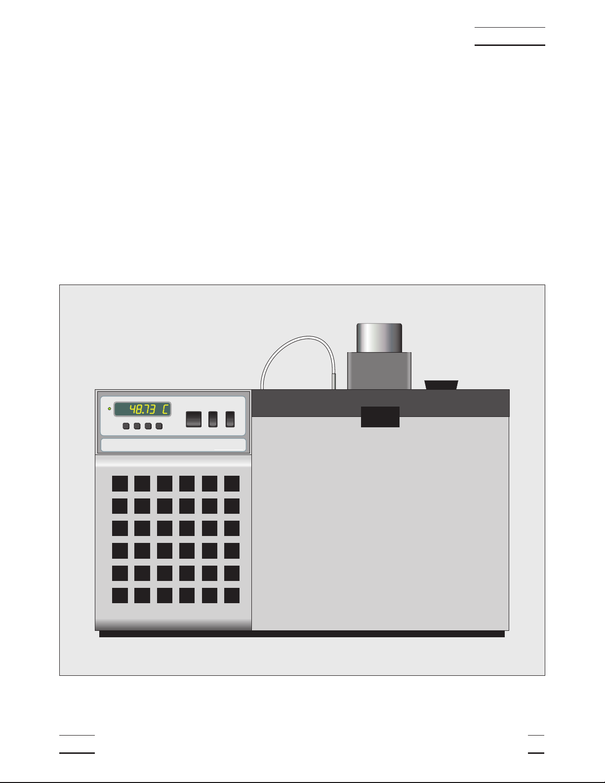
Figure 1 Bath Assembly . . . . . . . . . . . . . . . . . . . . . . . . 9
Table 1 Specifications . . . . . . . . . . . . . . . . . . . . . . . . 11
Figure 2 Front Panel . . . . . . . . . . . . . . . . . . . . . . . . . 23
Figure 3 Refrigeration Controls - Side Panel. . . . . . . . . . . . . 24
Figure 4 Back Panel . . . . . . . . . . . . . . . . . . . . . . . . . 26
Figure 5 Lid Options . . . . . . . . . . . . . . . . . . . . . . . . . 27
Table 2 Table of various fluids and their properties . . . . . . . . . 33
Figure 6 Chart of various bath fluids and their properties . . . . . . 34
Figure 7 Controller Flowchart. . . . . . . . . . . . . . . . . . . . . 38
Figure 8 Bath temperature fluctuation at various proportional
band settings . . . . . . . . . . . . . . . . . . . . . . . . 42
Table 3 Proportional Band — Fluid Table . . . . . . . . . . . . . . 43
Figure 9 Sample calibration computations . . . . . . . . . . . . . . 50
Figure 10 Wiring Diagram . . . . . . . . . . . . . . . . . . . . . . . 60
1 Introduction
The Hart Scientific Model 7011 is a very precise constant temperature bath.
An innovative state of the art solid-state temperature controller has been incor-
porated which maintains the bath temperature with extreme stability. The con-
troller uses a micro controller to execute the many operating functions.
User interface is provided by the 8-digit LED display and four key-switches.
The tank for the 7011 is stainless steel and holds 25 liters. The 7011 uses a
refrigeration system that is CFC free.
7011 Manual Rev. 881801 9
1 Introduction
High Precision Bath HART
SCIENTIFIC
SET DOWN UP EXIT
POWER
|
0
COOLING
|
0
HEATER
Figure 1 Bath Assembly

2 Specifications and Environmental
Conditions
2.1 Specifications
See Table 1.
2.2 Environmental Conditions
Although the instrument has been designed for optimum durability and trou-
ble-free operation, it must be handled with care. The instrument should not be
operated in an excessively dusty or dirty environment. Maintenance and clean-
ing recommendations can be found in the Maintenance Section of this manual.
The instrument operates safely under the following conditions:
7011 Manual Rev. 881801 11
2 Specifications and Environmental Conditions
Range –10°C to 110°C
Stability 0°C ±0.001°C
25°C ±0.0005°C
100°C ±0.0008°C
Uniformity ±0.001°C, ±0.002°C with oil at 100°C
Temperature Setting Digital display with push-button entry
Set-point Resolution 0.002°C; high-resolution mode, 0.00003°C
Display Temp. Resolution 0.01°C
Digital Setting Accuracy ±1°C
Digital Setting Repeatability ±0.005°C
Heaters 500 and 1000 watt
Access Opening 5” x 10” (127 x 254 mm)
Depth 12” (305 mm)
Wetted Parts 304 Stainless Steel
Power 115 VAC (±10%), 60 Hz, 13.2 amps
(230 VAC (±10%), 50 Hz 6.8 amps, option
available)
Volume 6.6 gallons (25 liters)
Size 21.5”H x 27” W x 15.5”D
(546 x 686 x 394 mm)
Weight 125 lbs (56.7 kg)
Table 1 Specifications

•temperature range: 5 - 50°C (41 - 122°F)
•ambient relative humidity: 15 - 50%
•pressure: 75kPa - 106kPa
•mains voltage within ± 10% of nominal
•vibrations in the calibration environment should be minimized
•altitude does not effect the performance or safety of the unit
2.3 Warranty
Hart Scientific, Inc. (Hart) warrants this product to be free from defects in ma-
terial and workmanship under normal use and service for a period as stated in
our current product catalog from the date of shipment. This warranty extends
only to the original purchaser and shall not apply to any product which, in
Hart’s sole opinion, has been subject to misuse, alteration, abuse or abnormal
conditions of operation or handling.
Software is warranted to operate in accordance with its programmed instruc-
tions on appropriate Hart products. It is not warranted to be error free.
Hart’s obligation under this warranty is limited to repair or replacement of a
product which is returned to Hart within the warranty period and is determined,
upon examination by Hart, to be defective. If Hart determines that the defect or
malfunction has been caused by misuse, alteration, abuse or abnormal condi-
tions or operation or handling, Hart will repair the product and bill the pur-
chaser for the reasonable cost of repair.
To exercise this warranty, the purchaser must forward the product after calling
or writing Hart for authorization. Hart assumes NO risk for in-transit damage.
For service or assistance, please contact the manufacturer.
Hart Scientific, Inc.
799 East Utah Valley Drive
American Fork, UT 84003-9775
Phone: (801) 763-1600
Fax: (801) 763-1010
E-mail: [email protected]
THE FOREGOING WARRANTY IS PURCHASER’S SOLE AND EXCLUSIVE
REMEDY AND IS IN LIEU OF ALL OTHER WARRANTIES, EXPRESS OR
IMPLIED, INCLUDING BUT NOT LIMITED TO ANY IMPLIED WARRANTY
OR MERCHANTABILITY, OR FITNESS FOR ANY PARTICULAR PURPOSE
OR USE. HART SHALL NOT BE LIABLE FOR ANY SPECIAL, INDIRECT, IN-
CIDENTAL, OR CONSEQUENTIAL DAMAGES OR LOSS WHETHER IN
CONTRACT, TORT, OR OTHERWISE.
12 Manual Rev. 881801 Hart Scientific
2 Specifications and Environmental Conditions

3 Safety Guidelines
•Operatethebathinroomtemperaturesbetween5-50°C(41-122°F).Allow
sufficient air circulation by leaving at least 6 inches of space between the
bath and nearby objects. Overhead clearance needs to allow for safe and
easy insertion and removal of probes for calibration.
•Ifthebathisusedathighertemperatureswherefluidvaporizationissignif-
icant, a fume hood should be used.
•Thebath isa precisioninstrument. Althoughit hasbeen designedfor opti-
mum durability and trouble free operation, it must be handled with care.
The instrument should not be operated in excessively dusty or dirty envi-
ronments.Do notoperate nearflammable materials.The evaporator pan-
els should be cleaned periodically.
•The bath generates extreme temperatures. Precautions must be taken to
prevent personal injury or damage to objects. Probes may be extremely
hotor coldwhen removedfrom thebath. Cautiouslyhandle probesto pre-
vent personal injury. Carefully place probes on a heat/cold resistant sur-
face or rack until they are at room temperature.
•Useonlya groundedACmains supplyofthe appropriatevoltageto power
the bath. The bath requires 13.2 amps at 115 VAC (±10%), 60 Hz (6.8
amps at 230 VAC [±10%], 50 Hz, optional).
•Beforeinitialuse,aftertransport,andanytimetheinstrumenthasnotbeen
energized for more than 10 days, the bath needs to be energized for a
“dry-out” period of 1-2 hours before it can be assumed to meet all of the
safety requirements of the IEC 1010-1.
•Thebathisequippedwithoperatoraccessiblefuses.Ifafuseblows,itmay
bedueto a powersurge or failureofa component.Replacethe fuse once.
Ifthefuseblowsasecondtime,itislikelycausedbyfailureofacomponent
part. If this occurs, contact Hart Scientific Customer Service. Always re-
place the fuse with one of the same rating, voltage, and type. Never re-
place the fuse with one of a higher current rating.
•If a mains supply power fluctuation occurs, immediately turn off the bath.
Power bumps from brown-outs and black-outs can damage the compres-
sor. Wait until the power has stabilized before re-energizing the bath.
•This bath is not designed to be portable. Therefore, moving the bath once
ithas been installed should bekept toa minimum.Never movea baththat
isfulloffluid.This actioncouldbeextremelydangerousandcouldresultin
personal injury to the person moving the bath. If the bath is going to be
placed in an area where it will need to be moved frequently, a special cart
can be designed to accommodate the bath. Thus making the bath much
more portable. Hart sells carts designed for these baths. However, even
with a cart the bath should not be moved full of “hot” fluid. The fluid can
splash causing injury or if the bath and cart tip, the fluid could cause dam-
age to the surrounding area and personal injury to personnel.
•If the bath must be moved, be sure to drain the fluid to prevent any injury.
The side of the bath with the compressor is heavier than the tank side. To
safely move the bath, two people are required.
7011 Manual Rev. 881801 13
3 Safety Guidelines

4 Quick Start
CAUTION
READ SECTION 6ENTITLED BATH USE
before placing the bath in service.
Incorrect handling can damage the bath and void the war-
ranty.
This section gives a brief summary of the steps required to set up and operate
the 7011 bath. This should be used as a general overview and reference and
not as a substitute for the remainder of the manual. Please read Sections 5
through 7carefully before operating the bath.
4.1 Unpacking
Unpack the bath carefully and inspect it for any damage that may have oc-
curred during shipment. If there is shipping damage, notify the carrier immedi-
ately.
Verify that all components are present:
•7011 Bath
•Access Hole Cover
•Controller Probe
•Manual
•Fill Hole Cover
•Power Cord
•Drain Elbow
If you are missing any item, please call Customer Service at 1-801-763-1600.
4.2 Set Up
Set up of the bath requires careful unpacking and placement of the bath, filling
the bath with fluid, installing the probe and connecting power. Consult Section
5for detailed instructions for proper installation of the bath. Be sure to place
the bath in a safe, clean and level location.
Fill the bath tank with an appropriate liquid. For operation at moderate bath
temperatures, clean distilled water works well. Carefully pour the fluid into the
bath tank through the large rectangular access hole above the tank avoiding
spilling any fluid. The fluid must not exceed a height of 3/4 inch below the bath
lid.
The control probe must be inserted through the lid into the bath and plugged
into the socket at the back of the bath.
7011 Manual Rev. 881801 15
4 Quick Start

4.3 Power
Plug the bath power cord into a mains outlet of the proper voltage, frequency,
and current capability. Typically this will be 115 VAC (±10%), 60 Hz, 13.2 A
[230 VAC (±10%), 50 Hz 6.8 A]. Set the “HEATER” switch on the front panel to
position “LOW” and turn the bath on using the front panel “POWER” switch.
The bath will turn on and begin to heat or cool to reach the previously pro-
grammed temperature setpoint. The front panel LED display will indicate the
actual bath temperature. The factory set set-point is 25°C
4.4 Setting the Temperature
In the following discussion a solid box around the word SET, UP, EXIT or
DOWN indicates the panel button while the dotted box indicates the display
reading. Explanation of the button or display reading are to the right of each
button or display value.
To view or set the bath temperature set-point proceed as follows. The front
panel LED display normally shows the actual bath temperature.
24.68 C
Bath temperature display
When “SET” is pressed the display shows the set-point memory that is cur-
rently being used and its value. Eight set-point memories are available.
S
Access set-point selection
1. 25.0
Set-point 1, 25.0°C currently used
Press “SET” to select this memory and access the set-point value.
S
Access set-point value
C 25.00
Current value of set-point 1, 25.00°C
Press “UP” or “DOWN” to change the set-point value.
U
Increment display
C 30.00
New set-point value
Press SET to accept the new value and display the vernier value. The bath be-
gins heating or cooling to the new set-point.
S
Store new set-point, access vernier
0.00000
Current vernier value
Press “EXIT” and the bath temperature will be displayed again.
16 Manual Rev. 881801 Hart Scientific
4 Quick Start

E
Return to the temperature display
24.73 C
Bath temperature display
The bath will heat or cool until it reaches the new set-point temperature. Set
the heater switch to position “HIGH” to allow the bath to more quickly reach a
higher temperature. The “HIGH” setting may be necessary to reach higher
temperatures and control at high temperatures.
When setting the set-point temperature be careful not to exceed the tempera-
ture limit of the bath fluid. The over-temperature cut-out should be correctly set
to prevent this from happening. See Section 9.8.
If operating the bath below 45 °C set the COOLING power switch to ON. The
cooling temperature may require adjustment to provide the proper amount of
cooling. See Section 8.5.
To obtain optimum control stability adjust the proportional band as discussed
in Section 9.7.
7011 Manual Rev. 881801 17
4 Quick Start

5 Installation
5.1 Bath Environment
The Model 7011 Bath is a precision instrument which should be located in an
appropriate environment. The location should be free of drafts, extreme tem-
peratures and temperature changes, dirt, etc. The surface where the bath is
placed must be level.
If used at higher temperatures where fluid vaporization is significant, use of a
fume hood is recommended.
CAUTION
READ SECTION 6ENTITLED BATH USE
before placing the bath in service.
Incorrect handling can damage the bath and void the war-
ranty.
This bath is not designed to be portable. Therefore, moving the bath once it
has been installed should be kept to a minimum.
Never move a bath that is full of fluid. This action could be extremely danger-
ous and could result in personal injury to the person moving the bath.
If the bath is going to be placed in an area where it will need to be moved fre-
quently, a special cart can be designed to accommodate the bath. Thus mak-
ing the bath much more portable. Hart sells carts designed for these baths.
However, even with a cart the bath should not be moved full of “hot” fluid. The
fluid can splash causing injury or if the bath and cart tip, the fluid could cause
damage to the surrounding area and personal injury to personnel.
If the bath must be moved, be sure to drain the fluid to prevent any injury. The
side of the bath with the compressor is heavier than the tank side. To safely
move the bath, two people are required.
5.2 “Dry-out” Period
Before initial use, after transport, and any time the instrument has not been
energized for more than 10 days, the bath will need to be energized for a
“dry-out” period of 1-2 hours before it can be assumed to meet all of the safety
requirements of the IEC 1010-1.
5.3 Bath Preparation and Filling
The Model 7011 Bath is not provided with a fluid. Various fluids are available
from Hart Scientific and other sources. Depending on the desired temperature
range, any of the following fluids, as well as others, may be used in the bath:
•Water
•Ethylene Glycol/Water
•Methanol
7011 Manual Rev. 881801 19
5 Installation

•Mineral oil
•Silicone oil
Fluids are discussed in detail in Section 8.1.
Remove any access hole cover from the bath and check the tank for foreign
matter (dirt, remnant packing material, etc.). Use clean unpolluted fluid. Care-
fully fill the bath through the large square access hole to a level that will allow
for stirring and thermal expansion. The fluid should never exceed a height of
3/4" below the top of the tank. Refer to the fill level indicator label on the right
rear side of the bath. Carefully monitor the bath fluid level as the bath temper-
ature rises to prevent overflow or splashing. Remove excess fluid if necessary
and with caution if the fluid is hot. Some fluids, especially oils, will expand
at higher temperatures. USE CAUTION.
Be careful to prevent bath fluid from spilling on the stirring motor while filling.
Note that underfilling may reduce bath performance and may possibly damage
the bath heater.
5.4 Probe
Inspect the bath controller probe. It should not be bent or damaged in any way.
Reasonable caution should be used in handling this probe as it contains a pre-
cision platinum sensor and is mechanically shock sensitive. Dropping, striking,
or other physical shock may cause a shift in resistance in the probe resulting
in diminished bath accuracy. If damaged, the probe can be replaced. Contact
the factory for assistance.
Insert the probe into the 1/4 inch probe hole at the top left side of the bath lid.
The tip of the probe must be well immersed in the fluid. The probe connector is
plugged into the rear of the bath into the socket labelled “PROBE”.
5.5 Power
With the bath power switch off, plug the bath into an AC mains outlet of the ap-
propriate voltage, frequency, and current capacity. Normally this will be 115
VAC (±10%), 60 Hz, 13.2 A [230 VAC (±10%), 50 Hz, 6.8 A].
Be sure the stirring motor power cord is plugged into the “STIRRER” socket at
the back of the bath.
20 Manual Rev. 881801 Hart Scientific
5 Installation

6 Bath Use
READ BEFORE PLACING THE BATH IN SERVICE
The information in this section is for general information only. It is not designed
to be the basis for calibration laboratory procedures. Each laboratory will need
to write their own specific procedures.
6.1 General
Be sure to select the correct fluid for the temperature range of the calibration.
Bath fluids should be selected to operate safely with adequate thermal proper-
ties to meet the application requirements. Also, be aware that some fluids ex-
pand and could overflow the bath if not watched. Refer to General Operation,
Section 8, for information specific to fluid selection and to the MSDS sheet
specific to the fluid selected. Generally, baths are set to one temperature and
used to calibrate probes only at that single temperature. This means that the
type of bath fluid does not have to change. Additionally, the bath can be left
energized reducing the stress on the system.
The bath generates extreme temperatures. Precautions must be taken to pre-
vent personal injury or damage to objects. Probes may be extremely hot or
cold when removed from the bath. Cautiously handle probes to prevent per-
sonal injury. Carefully place probes on a heat/cold resistant surface or rack un-
til they are at room temperature. It is advisable to wipe the probe with a clean
soft cloth or paper towel before inserting it into another bath. This prevents the
mixing of fluids from one bath to another. If the probe has been calibrated in
liquid salt, carefully wash the probe in warm water and dry completely before
transferring it to another fluid. Always be sure that the probe is completely dry
before inserting it into a hot fluid. Some of the high temperature fluids react vi-
olently to water or other liquid mediums. Be aware that cleaning the probe can
be dangerous if the probe has not cooled to room temperature. Additionally,
high temperature fluids may ignite the paper towels if the probe has not been
cooled.
For optimum accuracy and stability, allow the bath adequate stabilization time
after reaching the set-point temperature.
6.2 Comparison Calibration
Comparison calibration involves testing a probe (unit under test, UUT) against
a reference probe. After inserting the probes to be calibrated into the bath, al-
low sufficient time for the probes to settle and the temperature of the bath to
stabilize.
One of the significant dividends of using a bath rather than a dry-well to cali-
brate multiple probes is that the probes do not need to be identical in con-
struction. The fluid in the bath allows different types of probes to be calibrated
at the same time. However, stem effect from different types of probes is not to-
tally eliminated. Even though all baths have horizontal and vertical gradients,
these gradients are minimized inside the bath work area. Nevertheless, probes
7011 Manual Rev. 881801 21
6 Bath Use

should be inserted to the same depth in the bath liquid. Be sure that all probes
are inserted deep enough to prevent stem effect. From research at Hart Scien-
tific, we suggest a general rule-of-thumb for immersion depth to reduce the
stem effect to a minimum: 15 x the diameter of the UUT + the sensor length.
Do not submerge the probe handles. If the probe handles get too warm during
calibration at high temperatures, a heat shield could be used just below the
probe handle. This heat shield could be as simple as aluminum foil slid over
the probe before inserting it in the bath or as complicated as a specially de-
signed reflective metal apparatus.
When calibrating over a wide temperature range, better results can generally
be achieved by starting at the highest temperature and progressing down to
the lowest temperature.
Probes can be held in place in the bath by using probe clamps or drilling holes
in the access cover. Other fixtures to hold the probes can be designed. The
object is to keep the reference probe and the probe(s) to be calibrated as
closely grouped as possible in the working area of the bath. Bath stability is
maximized when the bath working area is kept covered.
In preparing to use the bath for calibration start by:
•Placing the reference probe in the bath working area.
•Placing the probe to be calibrated, the UUT, in the bath working area as
close as feasibly possible to the reference probe.
6.3 Calibration of Multiple Probes
Fully loading the bath with probes increases the time required for the tempera-
ture to stabilize after inserting the probes. Using the reference probe as the
guide, be sure that the temperature has stabilized before starting the calibra-
tion.
22 Manual Rev. 881801 Hart Scientific
6 Bath Use
7 Parts and Controls
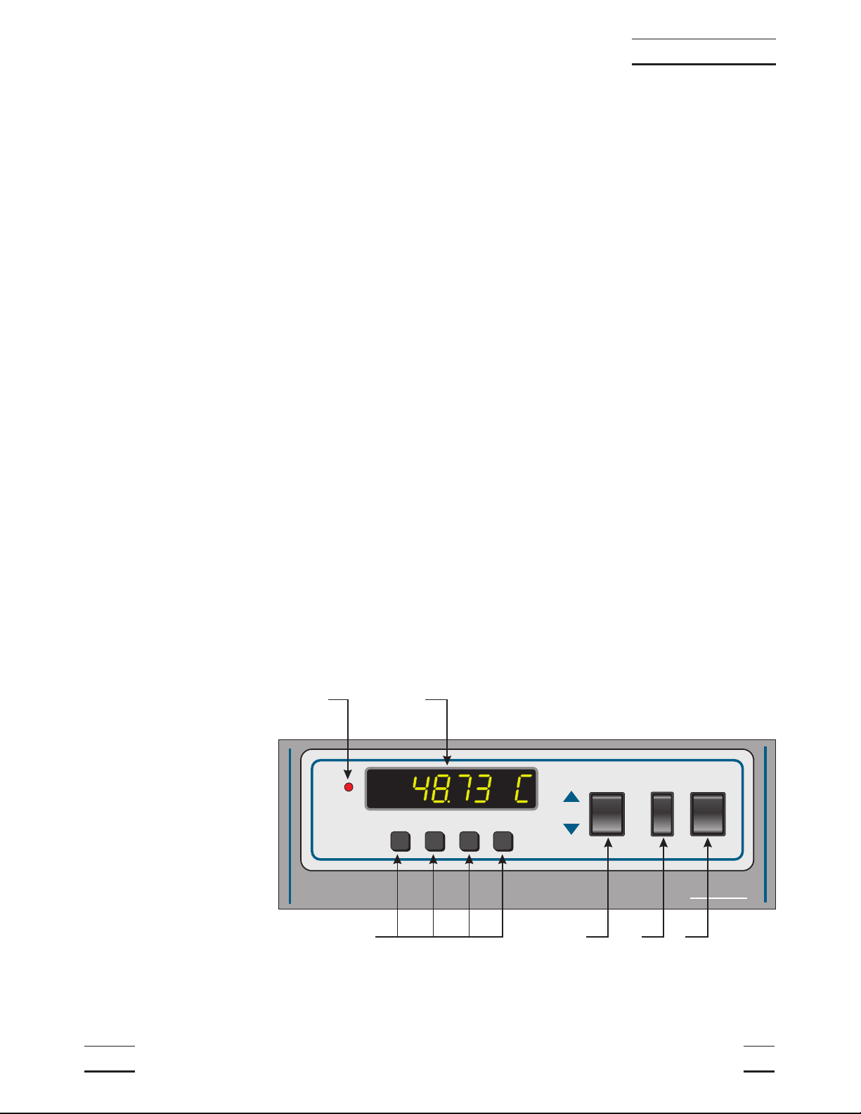
7.1 Front Control Panel
The following controls and indicators are present on the controller front panel
(see Figure 2below): (1) the digital LED display, (2) the control buttons, (3) the
bath on/off power switch, (4) the control indicator light, (5) the heater power
switch, and (6) the cooling power switch.
(1) The digital display is an important part of the temperature controller be-
cause it not only displays set and actual temperatures but also various bath
functions, settings, and constants. The display shows temperatures in values
according to the selected scale units °C or °F.
(2) The control buttons (SET, DOWN, UP, and EXIT) are used to set the bath
temperature setpoint, access and set other operating parameters, and access
and set bath calibration parameters.
A brief description of the functions of the buttons follows:
SET – Used to display the next parameter in a menu and to set parameters to
the displayed value.
DOWN – Used to decrement the displayed value of settable parameters.
UP – Used to increment the displayed value.
EXIT – Used to exit from a menu. When EXIT is pressed any changes made
to the displayed value will be ignored.
(3) The on/off switch controls power to the entire bath assembly. It powers the
stirring motor and the bath controller/heater circuit.
(4) The control indicator is a two color light emitting diode. This indicator lets
the user visually see the ratio of heating to cooling. When the indicator is red
the heater is on, and when it is green the heater is off and the bath is cooling.
7011 Manual Rev. 881801 23
7 Parts and Controls
High Precision Bath HART
SCIENTIFIC
SET DOWN UP EXIT
HIGH
LOW
COOLINGHEATING POWER
41
2365
O
I
O
I
Figure 2 Front Panel

When the indicator “toggles” red/green it has reached the set-point and is at-
tempting to control at that temperature.
(5) The heater power switch is used to select the appropriate heater power
levels for heating and controlling the bath at various temperatures.
(6) The cooling power switch controls power to the cooling compressor and
cooling fan.
7.2 Side Panel
The side panel has three features (see Figure 3): 1) the BACK PRESSURE
valve, 2) the COOLING TEMPERATURE regulating valve, and 3) the
COOLING TEMP gauge.
1) The BACK PRESSURE valve adjustment is used to control the amount of
cooling supplied to the system. This valve reduces the cooling capacity by
restricting the flow of refrigerant to the bath, allowing the adjustment of the
heatingtocoolingpercentage.Undernormaloperationthevalveshouldbe
fully open (counter clockwise).
2) The COOLING TEMPERATURE regulating valve is used to adjust the
pressure which determines the temperauture the refrigerant evaporates.
Refertothelablebelow thegaugeforapproximatepsi vsbathtemperature
settings. The table from the label is reproduced below.
24 Manual Rev. 881801 Hart Scientific
7 Parts and Controls
Back Pressure Cooling
Temperature
123
Figure 3 Refrigeration Controls - Side Panel
Table of contents
Popular Bathroom Fixture manuals by other brands


Grohe
Grohe Grohtherm F 35 028 manual

Hans Grohe
Hans Grohe Croma 04908 0 Series Installation/User Instructions/Warranty

BELLOSTA
BELLOSTA ponte vecchio B3-156 installation instructions

Hans Grohe
Hans Grohe Crometta 160 26578 1 Series Installation/User Instructions/Warranty

GODONNIER
GODONNIER 623011 quick start guide

Signature Hardware
Signature Hardware GLENLEY PRESSURE BALANCE 924918 installation manual

Anzzi
Anzzi SP-AZ016 install guide

Glacier bay
Glacier bay HDQF12A0023BNV Installation and care guide

Home Decorators Collection
Home Decorators Collection Leary HDC30HRV Assembly instructions

Santec
Santec E-Series installation instructions

Linie
Linie Mango Showertub installation guide

Laufen
Laufen SONAR 8.1134.1 Installation