Hartell L4 Owner's manual
Literature # 900986 2019
INTRODUCTION
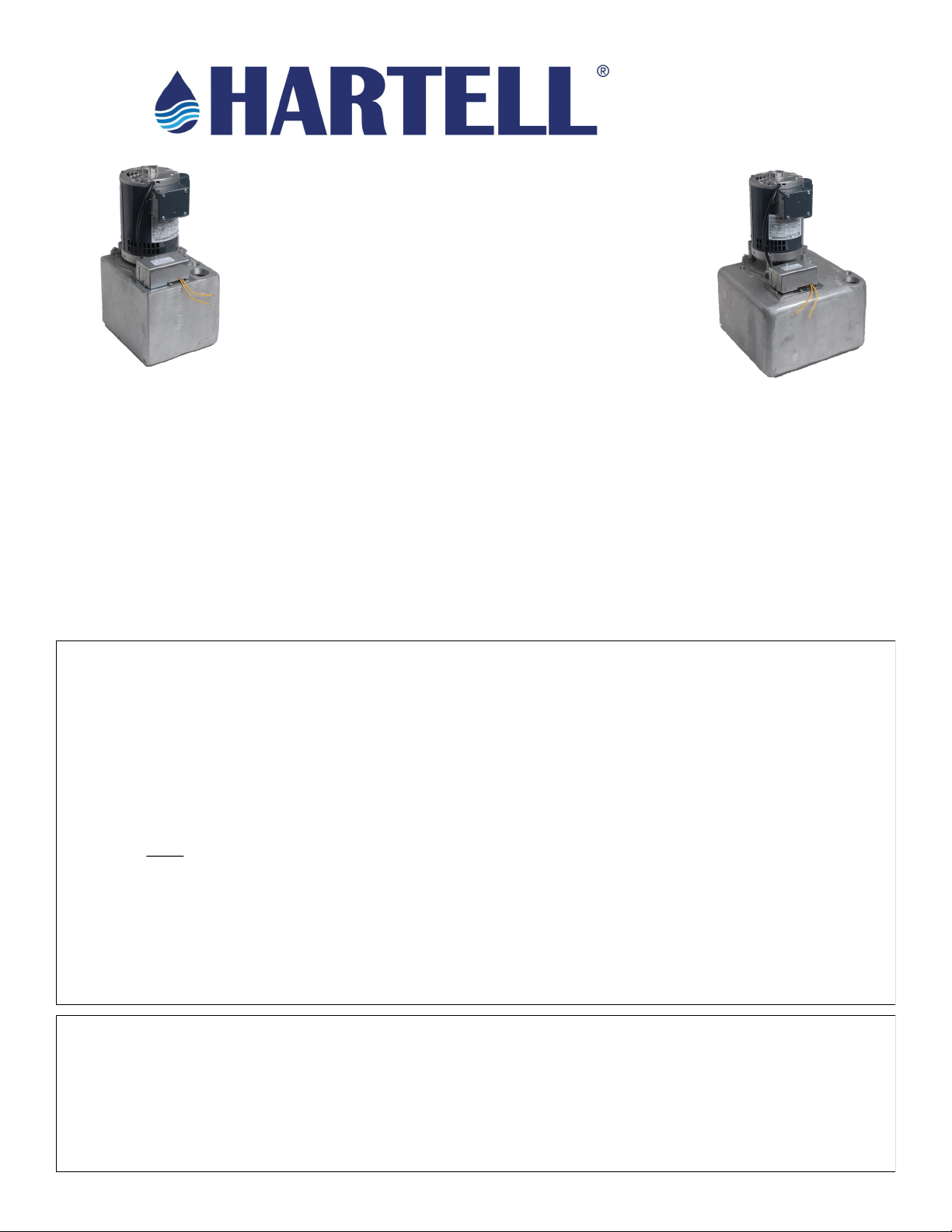
The HARTELL L4 is a heavy duty reservoir pump. The HARTELL SC-1A is a steam condensate return pump.
These models are utilized to pump wastewater from an area with no floor drains to an overhead or remote
drain line. These pumps have been carefully engineered to provide long, trouble free service and are of the
highest quality workmanship and materials.
These pumps have been thoroughly inspected and tested, then carefully packaged to insure safe delivery
and operation. When you receive your pump, examine it carefully to determine that there are no damaged
or broken parts. If damage is detected, notify the firm from where the pump was purchased. They will assist
with a repair or replacement.
See the precautions listed below before continuing.
CAUTION: READ ALL INSTRUCTIONS CAREFULLY BEFORE STARTING INSTALLATION
- Pump should only be used with liquids compatible with pump component materials. (Aluminum, SS) Do not
use to pump flammable or explosive fluids. Do not use in explosive atmospheres.
- The pump is supplied with a grounding wiring. To reduce the risk of electrical shock be certain that it is
connected to a properly grounded supply.
- Do not handle pump with wet hands or when standing on a wet or damp surface, or in water.
- Shut off the electrical power at the fuse box before making any connections. All wiring must comply with
local codes.
- A strainer must be installed in the tub to prevent foreign objects, (buttons, screws, etc.), from entering and
damaging the pump. In laundry applications a lint trap must be installed to prevent an excessive build-up of
lint that could interfere with proper float/switch and impeller operation. A nylon stocking works well as a lint
trap.
- Applying heat directly to the tank with a torch, or indirectly by heat transfer through copper tubing can melt
the tank. This will void the warranty. Solder fittings and tubing first, allow to cool, and then assemble to the
tank. Use only Teflon tape when installing threaded fittings to the tank.
ONE YEAR LIMITED WARRANTY
HARTELL L4 and SC-1A pumps are guaranteed to be free from defects in workmanship or materials and to function satisfactorily,
when properly installed, for a period of ONE (1) year from date of installation. HARTELL will replace, without charge, any HARTELL
product found to be defective upon examination at our factory if returned within the guarantee period, transportation charges
prepaid.
This guarantee does not apply if the product has been misapplied or mechanically damaged, HARTELL assumes no liability for
resultant damages of any kind arising out of the use of its products.
L 4 / SC-1A
W aste W ate r & S t e am
C o n d e n s a t e R e m o v a l P u m p s
I N S T A L L A T I O N
O P E R A T I O N
M A I N T E N A N C E
100 East Graham Place
Burbank, CA 91502
Web: www.hartell.com

Literature # 900986 2019
INSTALLATION
1. Place the pump in the desired location on the floor.
2. Install the piping necessary to connect the drain to the 1 ½” inlet. A trap is recommended. The use of
unions or slip fittings is also recommended to encourage proper pump maintenance. Install the vent line
and run it to a suitable location. This allows proper venting of the tank.
3. A check valve is required and should be of a soft seat swing check design. A spring loaded ball check is
permissible if the lift is one half of the pump shut off level and the spring pressure is equal to, or less than
one (1) psi.
4. The installation of a shutoff valve is recommended in the discharge line. This will allow the discharge flow
rate to be modified, if required to match inlet flow and prevent short cycling of the pump in low lift
installations. In addition, it will allow service to the check valve or the pump without draining the
discharge line.
5. Remove the tagged shipping pin to release the float for automatic operation.
ELECTRICAL CONNECTIONS
This pump uses a DUAL VOTAGE motor. It will operate on 115 or 230 VAC, 60 Hz, single phase power. THIS
UNIT IS FACTORY WIRED FOR 115 VAC OPERATION. Refer to the motor label for 230VAC wiring, if required.
Be sure to follow all applicable electrical codes
OPERATION
The L4 & SC-1A pumps operate automatically. Waste
water drains into the tank where it raises the float to
a pre-set power on point. The water is pumped out
the discharge and through the check valve to the
drain line. The float drops with the water level to a
pre-set power off point. The check valve keeps the
water from draining back to the tank. (check valve is
not included)
MAINTENANCE
The majority of maintenance is preventative. Keep
foreign objects out of the inlet and tank by using an
inlet screen and lint trap. Be aware that the vent line,
check valve, and discharge piping contribute to
system performance. Turn off power to the pump
before performing any maintenance or tests.
To inspect the tank interior and float/switch, remove
the five (5) switch screws that attach it to the tank.
Inspect and clean the float as required. If the tank
requires cleaning the pump must be removed from
the plumbing lines first.
LOW VOLTAGE—AUXILIARY SAFETY SWITCH–Units designated
with an ‘x’ in the model number (L4x) have a built in safety switch.
Connect the leads of auxiliary safety switch to the thermostat
control circuit of the air conditioner/furnace. This will disrupt the
thermostat demand in a high water condition. (Figure 1)
CAUTION –Thermostat demand disruption should not be utilized if
cooling or heating requirements are a necessity. An alarm system
should be used with the auxiliary switch instead.
The switch is wired normally closed. To wire for normally open
operation open the switch cover and move the yellow wire from
the bottom terminal to the middle terminal on the white switch.
Figure 1

Literature # 900986 2019
TROUBLESHOOTING
Problem Probable Cause
Pump does not run when
water is poured into the
reservoir.
- check that pump is plugged in
- check power to outlet or circuit
- fuse/breaker blown or tripped
- pump plugged into a switched outlet
Pump runs when plugged in
with no water in reservoir.
- damaged float/switch
- float “hanging-up” on tank wall due to buildup of soap scum or
debris
- check valve leaking back to tank
- shipping pin has not been removed
Pump runs but doesn’t empty
reservoir.
- clogged discharge line
- ball check valve spring pressure too high
- lift too high and/or run is too long (shutoff @ 40’)
- broken impeller/shaft
Pump leaks around motor and/
or float/switch
- damaged float/switch
- discharge too high
- discharge clogged
Pump doesn’t run, but has
water standing in reservoir.
- clogged vent line
- float “hanging-up” on tank wall due to buildup of soap scum or
debris
- damaged float/switch
Keep these sheets with the pump. They may be valuable if service is needed
under the terms of the warranty.
Model #: ______________________ Date of installation: __________________
Installer: ______________________ Date Code: __________________________
Dealer: ________________________
This manual suits for next models
1
Table of contents
Other Hartell Water Pump manuals

Popular Water Pump manuals by other brands


DROPSA
DROPSA 999 Series User and maintenance manual

Alemite
Alemite 8324 Service & operating manual

BUSCH
BUSCH R5 RA 1000 instruction manual

Ribimex
Ribimex Ribiland PRPVC249 1 User and maintenance manual

Pentair
Pentair ISO PRO Installation, operation and maintenance manual

SKF
SKF M Series Assembly instructions


