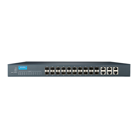
HARTING mCon 3000 User manual

HARTING Ha-VIS Management Soware
mCon 3000 Next Generation
User Manual Web Interface

All brand and product names are trademarks or registered trademarks of the owner concerned.
3rd Edition 2013, revised 10/13
© HARTING Electric GmbH & Co. KG, Espelkamp
Author: HARTING
Scriptor Dokumentations Service GmbH
Editor: HARTING
All rights reserved, including those of the translation.
No part of this manual may be reproduced in any form (print, photocopy, microlm or any other
process), processed, duplicated or distributed by means of electronic systems without the
written permission of HARTING Electric GmbH & Co. KG, Espelkamp.
Subject to alterations without notice.
Printed on bleached cellulose. 100% free from chlorine and acid.

3
Management Software Ha-VIS mCon Series / Edition 2.4
Content
1. Introduction ........................................................................................................................................................ 7
2. Safety Guidelines and Approved Usage .......................................................................................................... 8
3. General Notes about this Manual ..................................................................................................................... 9
3.1 Explanation of the symbols ................................................................................................................................. 9
3.2 Typographical conventions..................................................................................................................................9
3.3 Additional information..........................................................................................................................................9
4. Basic Operation................................................................................................................................................ 10
4.1 Switch access and conguration....................................................................................................................... 10
4.2 Web access.......................................................................................................................................................10
4.3 SNMP conguration .......................................................................................................................................... 11
5. Multifunction Button ........................................................................................................................................ 12
6. Introduction to the Web Browser Interface.................................................................................................... 13
6.1 The menus ........................................................................................................................................................ 13
6.2 Accept and saving changes with the Save Conguration button ......................................................................14
6.3 User rights......................................................................................................................................................... 16
7. Overview ........................................................................................................................................................... 17
8. System Settings ............................................................................................................................................... 19
8.1 General Settings and Switch Management....................................................................................................... 19
8.2 Port Settings......................................................................................................................................................21
8.3 User Management.............................................................................................................................................23
8.4 SNMP ...............................................................................................................................................................25
8.5 Network Discovery ............................................................................................................................................ 28
8.6 Time Settings ....................................................................................................................................................30
8.7 DHCP Relay Agent............................................................................................................................................ 33
8.8 File Transfer ......................................................................................................................................................34
9. PROFINET ......................................................................................................................................................... 38
10. Redundancy...................................................................................................................................................... 40
10.1 RSTP.................................................................................................................................................................40
10.2 MRP ..................................................................................................................................................................44
11. VLAN.................................................................................................................................................................. 47
11.1 Basic Settings ................................................................................................................................................... 47
11.2 Port Settings......................................................................................................................................................48
11.3 Static VLAN....................................................................................................................................................... 49
12. Quality of Service............................................................................................................................................. 50
12.1 Basic Settings ...................................................................................................................................................51
12.2 802.1p Priority Mapping ....................................................................................................................................51

4HARTING Electric GmbH 5
Management Software Ha-VIS mCon Series / Edition 2.4
Content
User Manual Ha-VIS mCon Switch Management Software
12.3 DiffServ Priority Mapping ..................................................................................................................................52
12.4 Rate Limiting .....................................................................................................................................................53
13. Security ............................................................................................................................................................ 54
13.1 IP Authorized Manager......................................................................................................................................54
13.2 Port based network access control IEEE 802.1x ..............................................................................................55
14. Link Aggregation............................................................................................................................................. 61
14.1 Basic Settings ...................................................................................................................................................61
14.2 Interface Settings ..............................................................................................................................................62
14.3 Port Settings......................................................................................................................................................63
15. Multicast............................................................................................................................................................ 65
15.1 Multicast IGMP Snooping..................................................................................................................................65
15.2 Basic Settings ...................................................................................................................................................65
15.3 Timer ................................................................................................................................................................. 66
15.4 VLAN Conguration ..........................................................................................................................................67
15.5 Router Ports...................................................................................................................................................... 68
15.6 Multicast Group................................................................................................................................................. 68
16. Alarm ................................................................................................................................................................. 69
16.1 E-Mail Alert........................................................................................................................................................ 69
16.2 SNMP Alert........................................................................................................................................................ 70
17. Diagnostics....................................................................................................................................................... 71
17.1 RMON ...............................................................................................................................................................71
17.2 Port Mirroring ....................................................................................................................................................75
17.3 Switch History ...................................................................................................................................................76
17.4 MAC Address Table........................................................................................................................................... 78
17.5 Light Beacon .....................................................................................................................................................79
17.6 Ping...................................................................................................................................................................79
18. Statistics ........................................................................................................................................................... 80
18.1 Interface statistics .............................................................................................................................................80
18.2 RSTP Statistics .................................................................................................................................................82
18.3 IGMP Snooping Statistics .................................................................................................................................83
19. SD Memory Card (optional) ............................................................................................................................. 84
20. Conguration with Automation Software Tool .............................................................................................. 86
20.1 Installing the Switch as a PROFINET Device ................................................................................................... 86
20.2 Hardware Conguration ....................................................................................................................................89
Appendix
Glossary of Terms and Abbreviations............................................................................................................ 94
Index.................................................................................................................................................................. 98
Figures
Figure 4-1 General Settings....................................................................................................................................... 11
Figure 5-1 Operating the Multifunction Button ...........................................................................................................12
Figure 6-1 Screen structure .......................................................................................................................................13
Figure 6-2 The menu tree ..........................................................................................................................................14
Figure 6-3 Save Conguration button........................................................................................................................ 14
Figure 6-4 Invalid entry: The exclamation point indicates an improperly formatted IP address................................. 15
Figure 7-1 The Overview section............................................................................................................................... 17
Figure 8-1 General Settings window.......................................................................................................................... 19
Figure 8-2 Switch Management window.................................................................................................................... 20
Figure 8-3 Basic Settings tab..................................................................................................................................... 21
Figure 8-4 Port Control tab ........................................................................................................................................22
Figure 8-5 User Management tab.............................................................................................................................. 23
Figure 8-6 Change Password tab ..............................................................................................................................24
Figure 8-7 SNMP section...........................................................................................................................................25
Figure 8-8 LLDP Settings tab (Network Discovery section)....................................................................................... 28
Figure 8-9 LLDP Connections (Network Discovery section)...................................................................................... 29
Figure 8-10 Advanced LLDP Settings (Network Discovery section)............................................................................ 30
Figure 8-11 Time Settings window...............................................................................................................................30
Figure 8-12 PTP Settings section ................................................................................................................................32
Figure 8-13 DHCP Relay Agent tab............................................................................................................................. 33
Figure 8-14 Import/Export Firmware tab...................................................................................................................... 34
Figure 8-15 Save/Load Conguration tab.................................................................................................................... 36
Figure 8-16 Reboot tab................................................................................................................................................ 37
Figure 9-1 PROFINET window ..................................................................................................................................38
Figure 9-2 IP settings in PROFINET Prole...............................................................................................................38
Figure 9-3 LLDP settings for PROFINET................................................................................................................... 39
Figure 10-1 Basic Settings tab..................................................................................................................................... 40
Figure 10-2 Port Settings tab....................................................................................................................................... 42
Figure 10-3 RSTP Port Status tab ...............................................................................................................................43
Figure 10-4 MRP Domain Settings with invalid SD card..............................................................................................44
Figure 10-5 MRP Domain settings with a valid SD card.............................................................................................. 44
Figure 10-6 MRP Domain − Basic Settings ................................................................................................................. 45
Figure 10-7 MRP Domain Status window .................................................................................................................... 46
Figure 11-1 VLAN Basic Settings tab ..........................................................................................................................47
Figure 11-2 VLAN Port Settings tab.............................................................................................................................48
Figure 11-3 Static VLAN Conguration tab.................................................................................................................. 49
Figure 12-1 Quality of Service – Tag Control Information (TCI)................................................................................... 50
Figure 12-2 QoS Basic Settings...................................................................................................................................51
Figure 12-3 802.1p Priority Mapping tab......................................................................................................................51
Figure 12-4 DiffServ Priority Mapping tab.................................................................................................................... 52
Figure 12-5 Rate Limiting.............................................................................................................................................53
Figure 13-1 IP Authorized Manager .............................................................................................................................54
Figure 13-2 802.1x Basic Settings tab......................................................................................................................... 55
Figure 13-3 Port Settings tab....................................................................................................................................... 56
Figure 13-4 Local Server tab .......................................................................................................................................57

6HARTING Electric GmbH
User Manual Ha-VIS mCon Switch Management Software
Figure 13-5 Radius Server Conguration tab ..............................................................................................................57
Figure 13-6 Supplicant Session Info tab...................................................................................................................... 58
Figure 13-7 Timers tab.................................................................................................................................................59
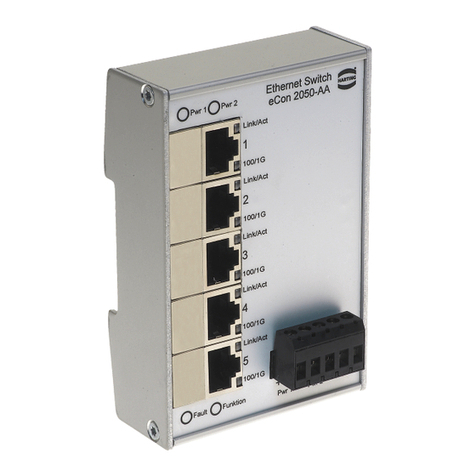
Figure 14-1 Link Aggregation Basic Settings tab......................................................................................................... 61
Figure 14-2 Link Aggregation Interface Settings tab.................................................................................................... 62
Figure 14-3 Link Aggregation Port Settings tab ...........................................................................................................63
Figure 15-1 IGMP Snooping Basic Settings tab ..........................................................................................................65
Figure 15-2 IGMP Timer tab ........................................................................................................................................66
Figure 15-3 IGMP Snooping VLAN Conguration tab ................................................................................................. 67
Figure 15-4 IGMP Snooping VLAN Router Ports tab...................................................................................................68
Figure 15-5 IGMP Snooping VLAN Multicast Group tab..............................................................................................68
Figure 16-1 E-mail Alarm tab .......................................................................................................................................69
Figure 16-2 SMTP Server Settings tab........................................................................................................................ 70
Figure 16-3 SNMP Trap section...................................................................................................................................70
Figure 17-1 Ingress Statistics tab ................................................................................................................................71
Figure 17-2 Egress Statistics tab................................................................................................................................. 72
Figure 17-3 Histogram tab ...........................................................................................................................................74
Figure 17-4 Port Mirroring section ...............................................................................................................................75
Figure 17-5 Switch History event list............................................................................................................................76
Figure 17-6 MAC Address Table ..................................................................................................................................78
Figure 17-7 Light Beacon functionality.........................................................................................................................79
Figure 17-8 Ping functionality ......................................................................................................................................79
Figure 18-1 Interface Statistics tab ..............................................................................................................................80
Figure 18-2 Ethernet Statistics tab...............................................................................................................................81
Figure 18-3 RSTP Information tab............................................................................................................................... 82
Figure 18-4 RSTP Port Statistics tab........................................................................................................................... 82
Figure 18-5 IGS Statistics tab...................................................................................................................................... 83
Figure 18-6 IGS V3 Statistics tab.................................................................................................................................83
Figure 19-1 Slot for SD card on the backside of the switch......................................................................................... 84
Figure 20-1 Installing the GSD le...............................................................................................................................86
Figure 20-2 Select GSD le ......................................................................................................................................... 87
Figure 20-3 Component library ....................................................................................................................................87
Figure 20-4 Adding a switch ........................................................................................................................................88
Figure 20-5 System characteristics..............................................................................................................................88
Figure 20-6 Assign Device Name ...............................................................................................................................88
Figure 20-7 Select the switch and assign the names ..................................................................................................89
Figure 20-8 Slots and modules of the Ha-VIS mCon 3000 Next Generation switches................................................ 89
Figure 20-9 Alarms on Slot 0 .......................................................................................................................................90
Figure 20-10 Topology settings...................................................................................................................................... 91
Figure 20-11 Transmission medium / duplex settings ...................................................................................................91
Figure 20-12 Port-related alarms................................................................................................................................... 92
Figure 20-13 QoS settings............................................................................................................................................. 92

7
Management Software Ha-VIS mCon Series / Edition 2.4
Introduction
1. Introduction
HARTING’s family Ha-VIS mCon of managed Ethernet switches are suitable for creating Ethernet,
Fast Ethernet and Gigabit Ethernet networks (up to 1000 Mbit/s) with distributed star or nodal
points in industrial environments where a high level of operational reliability is required.
Equipped with up to ten ports, the Ethernet switch can be mounted directly in the eld for
convenient networking of Ethernet devices. Your HARTING Ha-VIS mCon Ethernet Switch comes
with an embedded web server and a user-friendly web interface that makes switch management
intuitive and efcient. Conguration and maintenance are also possible using SNMP versions 1,
2 and 3 or using the Command Line Interface (CLI) via Telnet or ssh.
This software guide for the Ha-VIS mCon family of switches contains information required to
operate the switch management software. This information is applicable for all switches in the
Ha-VIS mCon 3000 NG series. The examples and screenshots in this manual are taken from the
Ha-VIS mCon 3102-AASFP; the number of ports and the information shown in your software may
vary depending on the model of switch you use.
This software guide has the following structure:
Chapters 1 to 3 Notes on safety and general information about this manual
Chapters 4 and 5 Basic information about the software, user rights, installation and
logging in
Chapters 6 to 18 Details about the software’s areas and windows and the settings that
can be made
Chapters 19 to 20 Information about SD Memory Card and other service
Appendix Glossary of terms and abbreviations, index

8HARTING Electric GmbH 9
Management Software Ha-VIS mCon Series / Edition 2.4
General Notes about this ManualUser Manual Ha-VIS mCon Switch Management Software
3. General Notes about this Manual
3.1 Explanation of the symbols
The following symbols are used in this software guide:
CAUTION
This symbol describes warning notes that indicate a low-level source of danger. If not avoided,
light or minor injuries or damage to property may result.
ATTENTION
This word describes warning notes that indicate a low-level source of danger. If not avoided,
damage to property may result.
Note
This symbol describes general notes that provide important information concerning one or more
operating steps. Such notes may also provide references to further information supplied within
this manual.
3.2 Typographical conventions
This manual uses the following typographical conventions to describe the software interface:
Italics Text in italic font refers to an entered value, a selection from a drop-
down list (such as Enable), a reference to a section of the software
menu (such as System Settings → General Settings) or drop-down
list choices.
Bold Text in bold font refers to the name of a row or column found within
the software interface, or to the name of a eld where data is
displayed or specied.
3.3 Additional information
Mounting instructions for this switch can be found in the Installation Notes included in the delivery.
The Installation Notes also provide valuable hardware-specic information such as the pin-out
assignments, LED displays, technical specications, and power supply requirements.
The latest versions of the switch rmware and the manual can be downloaded from the Internet
at http://www.HARTING.com.
2. Safety Guidelines and Approved Usage
In order to function properly, the switch management software must be correctly installed and
appropriately operated. The switch management software should be used only in conjunction
with a HARTING Ethernet switch.
Observe the following general safety instructions before installing and using the switch
management software:
• Ensure correct polarity and voltage when connecting the power supply to the Ethernet switch.
• Use only shielded cable for data lines.
• Use only cables that comply with the corresponding standards for Ethernet connections.
ATTENTION
The Ethernet switch should be operated only when it is properly and securely mounted.
CAUTION
Only authorized and qualied personnel are permitted to work on this device!
Improper work or repairs can damage the integrated protective safety functions and the
performance of this device. This can cause the device to malfunction, be a source of personal
danger, or cause damage to connected machines or connected systems.

10 HARTING Electric GmbH 11
Management Software Ha-VIS mCon Series / Edition 2.4
Basic OperationUser Manual Ha-VIS mCon Switch Management Software
5. Enter the network address of the switch into the browser. See the Installation Notes / Quick
Start Guide for more information about altering your computer’s network settings. The Login
Screen of the software will be displayed after your browser has successfully established an
HTTP connection to the switch.
6. Enter your username and password. Normally, the admin account is used for switch
administration. A guest account exists for viewing the conguration only. The default admin
password is harting. You should change this password as soon as possible.
Figure 4-1 General Settings
4.2.2 Logging out
To log out from the software at any time, simply click the Logout button in the top right-hand task
bar. The Login Screen is then once again displayed.
4.3 SNMP conguration
To get access to the switch using SNMP, an SNMP based software tool is needed. SNMP (Simple
Network Management Protocol) is the most widely-used network management protocol on TCP/
IP-based networks. SNMP provides an easy mechanism for managing a network using a simple
Command-Response protocol dened between the Manager and the managed entities. The
management is performed through MIBs (Management Information Base) supported by the
managed entities. The MIBs contain conguration elements, which can be either Viewed (GET)
or Modied (SET) by the Managers.
To access the switch, you need the following information:
• Switch IP address (Default value: 192.168.0.126)
• Community password to read values from the switch (Default value: public)
• Community password to read/write values from/to the switch (Default value: private)
For additional information refer to mCon 3000 NG User Manual SNMP.
4. Basic Operation
Make sure that the switch is securely mounted before starting any software conguration. Refer
to the Installation Notes for mounting instructions.
This Ethernet switch must rst be connected to your local area network before it can be congured.
The switch management software and the embedded web server are pre-installed on the switch.
You will require a networked computer with an HTTP web browser or an SNMP Tool to congure
the switch management software. Optionally you can also install a TFTP server program on
this PC in the event that you need to update the switch rmware or export respectively import a
conguration le.
4.1 Switch access and conguration
The Ha-VIS mCon switches offer a variety of software functionalities to congurate and set up the
network. For conguration purpose, the switch can be accessed in several ways.
The easiest way is to use a standard web browser to congurate the switch via a graphical HTTP
based user interface. To connect to the switch, the user must log in to the switch using the web
browser (following the instructions below). The user must log out before exiting the browser,
because the parallel connections to the switch (web sessions) are limited to two and the timeout
for each session is 10 minutes. Once you logged out, you can close the browser window in which
the web interface was running.
The second way is to access the switch via an SNMP software. The Ha-VIS mCon Ethernet
Switches are supporting the standard MIB II and can be easily integrated to an existing LAN
infrastructure and management suite. Some functionalities are product and HARTING specic
and therefore are not included in the MIB II. To get also access to this functionalities using SNMP,
you have to copy the HARTING MIB le to your MIB repository of your SNMP software.
The third way of conguring the switches is to use the command line interface (CLI). The CLI
can be accessed using the network protocols TELNET or SSH. Most operating systems are
equipped with a TELNET client. Alternatively clients like PuTTY can be used. After logging in
to the system, you will reach the prompt to enter the commands for conguring the switch. For
detailed information on how to use the command line interface, refer to the CLI manual.
4.2 Web access
4.2.1 Logging in
Proceed as follows to turn on the switch and to login in:
1. Connect the switch to your network or to a service computer using an Ethernet patch cable.
You may select any free port on the switch.
2. Connect the switch to the power supply (refer to the Installation Notes). The switch will take
about thirty seconds to boot up.
3. Turn on a computer connected to the same network as the switch. If you are starting with a
brand new switch, you should initially congure your host PC so that it is on the same network
segment as the switch (the switch has a factory default IP of 192.168.0.126, and a subnet
mask of 255.255.255.0).
4. Start your web browser or open a new browser window.

12 HARTING Electric GmbH 13
Management Software Ha-VIS mCon Series / Edition 2.4
Introduction to the Web Browser InterfaceUser Manual Ha-VIS mCon Switch Management Software
6. Introduction to the Web Browser Interface
The web interface offers a simple way to manage the software functionalities of the Ha-Vis mCon
Ethernet Switches. The websites will be refreshed automatically in short intervals.
One of the following web browser versions should be used for switch conguration:
• Microsoft Internet Explorer version 7 or later
• Firefox version 2 or later
6.1 The menus
The structure of the software interface has been kept simple. After logging in to the mCon
homepage, you will see a main navigation menu tree on the left side and an active window in the
middle right side of the browser window. Using the menu tree, you can access all of the settings
and statistics available on the switch. On the top you nd the options for refreshing the window
or to logout form the web interface. The menu bar at the bottom shows an overview of general
switch parameters and also the status of the conguration storage.
Figure 6-1 Screen structure
AThe top task bar
BThe menu tree
CThe active window
DThe bottom task bar
6.1.1 The top task bar
The task bar at the top of the window contains links to Support, About and Logout. It is necessary
to use the logout button before closing the browser, to be sure that the web session is terminated
correctly.
5. Multifunction Button
Via the Multifunction Button (MFB) the customer is able to set some specic parameters of the
switch, without accessing it via Web or SNMP.
This chapter describes how to use the MFB and the Service Mode.
Figure 5-1 Operating the Multifunction Button
Operation sequence:
The operation of the MFB is available after the switch has nished the boot up.
The selection of each function is displayed via the 100 Mbit/s LEDs.
If the MFB is pressed the rst time (rst press 3 sec), the yellow LEDs for displaying the
100 Mbit/s mode are disabled for all ports and the red Fault LED is lit continuously to show that
the conguration via the button is possible.
After pressing the button for the rst time, the 100 Mbit/s LED on port 1 is lit and the function (Reboot)
is selected.
When the button is pressed for a second time, the LED of port 2 is lit and the second mode is
selected.
Select the function by tapping the MFB an according number of times. Now, the switch is waiting three
seconds for further commands. The selection will be conrmed by two ashes of the red Fault LED.
Should no action be executed, the MFB must be pressed until all 100 Mbit/s LEDs are off and the
switch returns to normal operation (red Fault LED off again).
# Function Description
1 Reboot Hardware reset
2 Set DHCP Sets the IP address mode to DHCP
3 Set static IP Sets the IP address to 192.168.0.126 and subnet mask to 255.255.255.0
4 Enable PROFINET Enables PROFINET
5 Disable PROFINET Disables PROFINET
6 Reset to factory defaults Sets the switch to factory default settings
7 Reset to factory defaults,
keep IP
Set the switch to factory default settings with the exception of the IP
address
A
B
C
D

14 HARTING Electric GmbH 15
Management Software Ha-VIS mCon Series / Edition 2.4
Introduction to the Web Browser InterfaceUser Manual Ha-VIS mCon Switch Management Software
Assuming conguration changes and permanently saving them
• The software maintains any conguration changes in volatile memory after pressing the Apply
button.
• The administrator must explicitly trigger the save operation (bottom bar after changing
parameters.
• When triggered, the software saves the full conguration.
• Any old contents in the cong-le is over-written.
• When the switch is restarted, the software starts with the last conguration saved to the ash.
Note
The Apply button only saves your changes temporarily until the next reboot. You have to click on
the subsequent SAVE CONFIGURATION button in order to save the changes persistently.
6.3
If you specify an invalid entry (for example, an out-of-range timer value or improperly formatted IP
address), a red exclamation mark is displayed next to the error eld to notify the user of the error.
Figure 6-4 Invalid entry: The exclamation point indicates an improperly formatted IP address.
6.1.2 The menu tree
A clickable, two-level menu located on the left of the browser window is used to navigate through
the switch functionality. You can view or change switch settings and statistics by clicking on any
of the various second-level menu choices.
Figure 6-2 The menu tree
6.1.3 The active window
Most of the screen is taken up with the active window, in which settings and statistics for the
switch are displayed and congured. The active window consists of several tabbed sub-windows.
The right-most tabbed section is marked with a question mark and contains helpful explanations
for the corresponding settings.
6.1.4 The bottom task bar
On the left side the IP Address, the Subnet Mask, the MAC Address and the installed rmware
version of the switch is displayed. On the right side, the current conguration storage status is
shown.
6.2 Accept and saving changes with the Save Conguration button
After modifying a setting (e.g. by checking a box or specifying a value), please click on the Apply
button located at the bottom of the active window to conrm the change. Note that the Apply
function only temporarily saves the changes to the RAM. For a short time after the opening of a
window, the Apply button is highlighted grey. The Apply button is also activated, when settings
or alterations are made in the window. In this case, it appears in a bold font to remind you that
settings have been made or altered and that these have to be conrmed by clicking the Apply
button. After this is done, a SAVE CONFIGURATION button appears in the bottom bar. Click the
button to save your changes permanently in the ash memory to make the conguration also
existent after a power down or a software reboot.
Figure 6-3 Save Conguration button

16 HARTING Electric GmbH 17
Management Software Ha-VIS mCon Series / Edition 2.4
OverviewUser Manual Ha-VIS mCon Switch Management Software
7. Overview
After you log in to the switch, the active window displays an overview of the switch and the main
settings for each of the ports. No changes can be made in this window. To access this section,
simply click on Overview in the two-level menu tree displayed at the left of the window.
The top right section of the Overview window contains an illustration of the particular Ethernet
switch you are connected to. In addition, general information is displayed at the top left of the
Overview window:
Figure 7-1 The Overview section
Function Description
Device Name Displays the type of HARTING Ethernet switch in use.
Default value:
Ha-VIS mCon 3080-A, Ha-VIS mCon 3102-AASFP
Device Contact Displays contact information, as dened by the user in the General
Settings section.
Device Location Displays the location of the device, as dened by the user in the
General Settings section.
Device Description MAC address of the switch
Part No. Displays the HARTING part number of the switch.
Hardware Version Displays the hardware version number of the switch management
board.
Firmware Version Displays the rmware version number of the switch.
WebUI Version Displays the version of the web interface.
Port Count Displays the number of ports.
IP-Address Displays the currently assigned IP address on the switch.
MAC-Address Displays the unique hardware MAC address on the switch.
Device Up Time Displays the duration that the switch has been powered up.
6.4 User rights
There are two pre-dened user modes for accessing the Ethernet switch web-based software:
Function Description
Guest The access category Guest enables all areas of the software to be
viewed only.
Admin The access category Admin enables all areas of the software to be
viewed and administered. No restrictions apply to making settings
or alterations. This is the normal administrative user account for
making switch settings.

18 HARTING Electric GmbH 19
Management Software Ha-VIS mCon Series / Edition 2.4
System SettingsUser Manual Ha-VIS mCon Switch Management Software
8. System Settings
The System Settings section is composed of the following sub-sections: General Settings, Port
Settings, User Management, SNMP, Network Discovery, Time Settings, DHCP Relay Agent and
File Transfer. All of this sections are described below.
8.1 General Settings and Switch Management
8.1.1 General Settings
In order to commission the Ethernet switch, the IP address and subnet mask must rst be modied
for the connected network (refer to the Quick-start Guide for setup instructions). If a DHCP server
(Dynamic Host Conguration Protocol) is running on your LAN, you can specify Dynamic in the
IP Address Mode settings.
Figure 8-1 General Settings window
The following general settings can be displayed or specied:
Function Description
Device Name Specify a descriptive text for the device name.
Device Contact Specify a descriptive text for the device contact.
Device Location Specify a descriptive text for the device location.
IP Address Mode Specify the switch IP addressing mode. If Dynamic is selected in
the drop-down list, the switch is assigned with a valid IP address
and subnet mask during system initialisation by the DHCP server.
If Manual is selected, the IP address and the subnet mask must be
entered manually.
DHCP Fast Access The function accelerates the DHCP addressing in large networks.
The standard timeouts and waiting periods are reduced to a
minimum. It is recommended to set this option to enable, if Option
82 is used.
IP Address Specify the IP address of the switch. IP addresses are assigned
automatically if a DHCP server is activated.
Note
The IP address assigned to the switch must be unique for the respective network! Connectivity
problems will arise if two network components are assigned the same IP address.
The table at the bottom of the Overview window has the following columns for each port (see
table below).
Note
It is impossible to change information in the Overview window. Basic port settings can be altered
from the System Settings → Port Settings menu section.
Function Description
Port Displays all available switch ports.
Jack Type Displays the compatible media or jack type for the port (RJ45, or
SFP).
Status Displays the current status of the port. Enable means that the port is
enabled; Disable is displayed if the port is disabled. (A port can be
disabled in the System Settings → Port Settings section.)
Link Displays the status of the port. A red circle indicates that there is
currently no existing link, while a green circle indicates an existing
link.
Auto Neg Displays the negotiation state. Auto-negotiation is a technology for
ensuring compatibility of a network component with the network.
This column indicates if the Auto-negotiation function for the port is
activated (ON) or deactivated (OFF).
Data Rate Displays the data transfer mode for the respective port.
Duplex mode Displays the port duplex mode. Half duplex means that data ows in
one direction via the port at a given time; Full duplex enables data
ow in both directions.

20 HARTING Electric GmbH 21
Management Software Ha-VIS mCon Series / Edition 2.4
System SettingsUser Manual Ha-VIS mCon Switch Management Software
Management
Function Description
Default/Mgmt-VLAN
ID:
Change of the Management VLAN
Range of value: 1 ... 4094
Default value: 1
HTTP Port Sets the http port for the web interface.
Range of value: 1 ... 65535
Default value: 80
Multifunction Button Enable or disable the Multifunction Button on the switch
Range of value: Enable / Disable
Default value: Enable
8.2 Port Settings
This section informs you on how to change the settings for the switch’s Ethernet ports. The ports
can be individually enabled (up) or disabled (down). The data transfer rate and mode of data ow
can be determined as well as the compatibility parameters for the network. Note that there are
two tabbed sections (Basic Settings and Port Control) where these settings can be made.
8.2.1 Basic Settings
Figure 8-3 Basic Settings tab
In this tabbed section, the administrative state of individual ports can be specied. Each port row
has the following columns.
Function Description
Select/Port Select the port that you would like to change by clicking on the
checkbox here.
Admin State Select the desired state of the port. A port can be either enabled (up)
or disabled (down).
Range of value: UP / DOWN
Default value: UP
Link Status Displays the port status. A green circle in this column indicates that a
device is connected to this port. A red circle indicates that no device
is connected.
Function Description
Save IP Address
Persistent
Check this box to save the IP address permanently. You will no
longer be able to connect to the switch using the old IP address.
Using your web browser, connect to the switch using the new IP
address.
Subnet Mask Specify the subnet mask for the network. If the subnet mask is
entered manually. This value is assigned automatically if you have
a DHCP server.
Default Gateway Specify the default gateway for the switch
Be sure to remember to click on the Apply button to save your changes. Then click on the Save
Conguration button which appears at the bottom of the window to save the settings permanently.
The lower section of the General Settings window lists additional status information. This includes:
the switch MAC address, the default VLAN identier, the conguration save status, the remote
save status, the conguration restore status and the HTTP port number.
8.1.2 Switch Management
This chapter describes the conguration of the various system and session related features,
like web session and service functionalities.
Figure 8-2 Switch Management window
Web Session
Function Description
Web Session Timeout Sets the timeout for each web session. Without any action on the web
interface, the session will be terminated after the timeout timer expires.
Range of value: 1 ... 3600 seconds
Default value: 600
Maximum Number of
Web Sessions
Sets the maximum number of parallel web sessions.
Range of value: 1 ... 10
Default value: 2

22 HARTING Electric GmbH 23
Management Software Ha-VIS mCon Series / Edition 2.4
System SettingsUser Manual Ha-VIS mCon Switch Management Software
8.3 User Management
This section allows you to create new users and to specify a new password for the admin or guest
account.
8.3.1 User Management
Figure 8-5 User Management tab
Create User To create a new user you must be logged in to the switch as an
administrator. It is possible to create new Guest and Admin accounts.
After the required information has been entered, the Apply button
must be pressed and nally the creation of the new account must
be veried with the password of the actual logged in user account.
User List All users existing on the switch are shown in this list. The maximum
of users is limited to 20. Selected users can be deleted from the
switch by pressing the delete button on the bottom. The default
admin account can only be deactivated, if another admin account
was created on the switch rst. You must be logged in via this new
admin account to deactivate the Default Admin account.
8.2.2 Port Control
Figure 8-4 Port Control tab
In this tabbed section, the characteristics of individual ports can be specied in the following columns:
Function Description
Select/Port Select the port that you would like to change by clicking on the
checkbox here.
Autonegotiation
Select whether Autonegotiation is disabled or enabled. Autonegotiation
is a function which enables the participating interfaces to automatically
determine the best possible transmission parameters. The auto-
negotiation function can either be activated (Enable) or deactivated
(Disable). If Enable is selected, the auto-negotiated settings will be used
and the data-rate and duplex columns will be greyed out.
Range of value: Enable / Disable
Default value: Enable
Duplex Select the data transmission mode for the respective port from the drop-
down list. Half means that data ows in only one direction via the port at
a given time; Full enables data to ow in both directions simultaneously.
Range of value: Half / Full
Default value: Full
Speed Select the data transmission rates for the port from the drop-down
list: 100 Mbit/s or 10 Mbit/s, 100 Mbit/s or 1 Gbit/s, depending on the
type of port interface.
Range of value: 10 Mbit/s or 100 Mbit/s / 100 Mbit/s or 1 Gbit/s
Default value: Physical maximum
Flow Control Admin
Status
Select if ow control is activated (Enable) or deactivated (Disable). If
enabled, the port sends out Pause frames when the buffer capacity
reaches a certain limit.
Range of value: Enable / Disable
Default value: Disable
Autocrossing The automatic crossover of the RX / TX lines can be switched from the
standard auto mode in the following modes: MDI (no crossing of lines),
MDIX (RX / TX lines are crossed) and AUTO (automatic crossover).
Range of value: MDI / MDIX / AUTO
Default value: AUTO
Note
For the usage of the Ha-VIS mCon 3102-AASFP the following restrictions apply: Depending on
the capabilities of the used SFP-modules the adjustable parameters may vary. For example, it is
not possible to deactivate Autonegotiation and Autocrossing for Gigabit SFP-Modules.

24 HARTING Electric GmbH 25
Management Software Ha-VIS mCon Series / Edition 2.4
System SettingsUser Manual Ha-VIS mCon Switch Management Software
8.4 SNMP
SNMP (Simple Network Management Protocol) is the most widely-used network management
protocol on TCP/IP-based networks. SNMP provides an easy mechanism for managing a
network using a simple Command-Response protocol dened between the Manager and the
managed entities. The management is performed through MIBs (Management Information Base)
supported by the managed entities. The MIBs contain conguration elements which can be either
Viewed (GET) or Modied (SET) by the Managers.
SNMPv3 is designed mainly to overcome the security shortcomings of SNMPv1/v2. USM (User
based Security Model) is the main feature added as part of the SNMPv3 specication. USM
provides for both encryption and authentication of the SNMP PDUs. With SNMPv3, the SNMP
communication is completely safe and secure.
The conguration of the switch can be accessed and changed directly using SNMP commands.
This section allows you to specify the basic SNMP settings. This switch software supports SNMP
versions 1/2c and 3. You may also enable both versions simultaneously.
Figure 8-7 SNMP section
8.3.2 Change Password
Figure 8-6 Change Password tab
The switch software is password-protected to prevent unauthorized access. The admin password
should consist of at least six characters. The password must always be entered to gain access
to the software.
There are two access levels, which can be chosen from the drop-down list:
Function Description
Admin All rights are available.
Guest All settings and values can only be viewed. It is not possible to alter
the password or other settings.
The system administrator is authorized to alter the valid password for the access levels for the
administrator and guest in this section. The admin password must be specied correctly before
you can change a password. Click Apply to conrm your entry. The new password will become
valid when the switch is rebooted.
If the administrator password is forgotten or if it becomes necessary to alter it due to technical
reasons, this process can be carried out using the Multifunction Button. To learn how to use the
Multifunction Button refer to Chapter 5 – „Multifunction Button“.

26 HARTING Electric GmbH 27
Management Software Ha-VIS mCon Series / Edition 2.4
System SettingsUser Manual Ha-VIS mCon Switch Management Software
Function Description
Authentication
Protocol
Protocol used for User Authentication (MD5) or Secure Hash
Algorithm (SHA)
Range of value: MD5 / SHA
Default value: MD5
Authentication Specify the SNMPv3 password. It must be at least eight characters.
Range of value: Not more than 20 printable characters
Default value: none
Authentication Retype
Password
Repeat the specied SNMPv3 password.
Privacy Protocol Protocol used for privacy.
Range of value: DES
Default value: DES
Privacy Password Specify the SNMPv3 privacy password.
Range of value: Not more than 20 printable characters
Default value: none
Privacy Retype
Password
Repeat the specied SNMPv3 privacy password.
Note
If you don’t plan to use SNMP, you should make sure that both versions are disabled so that
maximum security is ensured.
Note
A MIB (Management Information Base) le can be found on the enclosed CD. With the MIB
information you get open-standard access to the switch using SNMP management software.
8.4.1 SNMP V1/V2C
For V1/V2 operations, the HARTING SNMP Agent provides a community-based Security
Mechanism. Community names are encoded into V1/V2 messages and the Agent veries the
privilege status of the community name before responding to it. Community names are associated
with the privilege status. The privilege status can be of the types read-only or read-write.
Function Description
Enable Check this box to launch the SNMP agent and allow access to the
switch via SNMP version 1/2c.
Range of value: Enable / Disable
Default value: Enable
Read Community Specify the community name for SNMP read access. The default is
public.
Range of value: Not more than 20 printable characters.
Default value: public
Read/Write
Community
Specify the community name for SNMP read and write access. The
default is private. This community string acts as an SNMP password;
you should pick one that it difcult to guess.
Range of value: Not more than 20 printable characters
Default value: private
8.4.2 SNMP V3
The HARTING SNMP Agent provides complete support for User based Security Model.
The following security algorithms are supported:
• Authentication HMAC MD5 and HMAC- SHA
• Encryption DES-CBC
Three levels of security are supported.
• NoAuthNoPriv No Authentication and no Privacy
• AuthNoPriv Authentication and no Privacy
• AuthPriv Authentication and Privacy
Function Description
Enable Check this box to launch the SNMP agent and allow access to the
switch via SNMP version 3.
Range of value: Enable / Disable
Default value: Enable
User Specify the user name for SNMP version 3 access.
Range of value: Not more than 20 printable characters.
Default value: harting
Access Level NoAuthNoPriv No authentication and no message encryption
AuthNoPriv Enables message digest (MD5) or Secure Hash
Algorithm (SHA) packet authentication, but no
message encryption
AuthPriv Both authentication and message encryption.
Range of value: NoAuthNoPriv / AuthNoPriv / AuthPriv
Default value: AuthPriv

28 HARTING Electric GmbH 29
Management Software Ha-VIS mCon Series / Edition 2.4
System SettingsUser Manual Ha-VIS mCon Switch Management Software
Function Description
Activate LLDP Select whether to disable or enable LLDP globally on the switch.
Range of value: Enable / Disable
Default value: Disable
Chassis ID Subtype Select the Chassis ID Subtype which should be included in the LLDP
packets.
Range of value: MAC Address / Interface Alias /
Network Address / Custom
Default value: MAC Address
Chassis ID Select the Chassis ID which should be included in the LLDP packets.
Transmit Interval The interval at which LLDP frames are transmitted on behalf of
this LLDP agent. The default value for the Transmit Interval is 30
seconds.
Range of value: 5, 10, 30, 60, 120 sec
Default value: 30 sec
TTL Multiplier Time-to-live value expressed as a multiple of the Transmit Interval
Range of value: 2, 3, 4, 5, 10
Default value: 4
Send IP Address Option to transmit switch’s IP adress with every LLDP packet
Range of value: Enable / Disable
Default value: Disable
Table description Via the table, the Port ID can be set for each port individually.
Note
The interval between to LLDP PDUs is calculated using the following algorithm:
LLDP Interval = Transmit Interval x TTL Multiplier
8.5.2 LLDP Connections
Figure 8-9 LLDP Connections (Network Discovery section)
The LLDP Connections table shows all directly connected neighbours and the corresponding
information. The Refresh button allows you to refresh your view of neighbouring chassis IDs, port
IDs, and IP addresses. The following information are shown:
• Local Port Local port where the information was learned
• Neighbour Chassis ID Chassis ID of the neighbour device
• Neighbour Port ID Port ID of the neighbour device
• Neighbour IP IP address of the neighbour device
8.5 Network Discovery
This section allows you to activate and congure LLDP (Link Layer Discovery Protocol). LLDP
can be used to determine the capabilities of devices on your network. It allows the switch to
announce its capabilities and other media-specic conguration information to the local area
network.
The LLDP allows systems on an Ethernet LAN to advertise their key capabilities and to learn
about the key capabilities of other systems on the same Ethernet LAN. Consequently, this
promotes a unied network management view of the LAN topology and connectivity to support
network administration and trouble-shooting. The station and capabilities information is conveyed
in protocol frames called Link Layer Discovery Protocol Data Units (LLD PDUs). In general, a
network administration station can be connected to one single switch getting access from there
to the connectivity information of the complete network within an enterprise. The switch also
provides notications in form of SNMP traps to alert the operator about changes in the network
topology.
8.5.1 LLDP Settings
Figure 8-8 LLDP Settings tab (Network Discovery section)
The Refresh button at the bottom of this window allows you to refresh your view of neighbouring
chassis IDs, port IDs, and IP addresses.

30 HARTING Electric GmbH 31
Management Software Ha-VIS mCon Series / Edition 2.4
System SettingsUser Manual Ha-VIS mCon Switch Management Software
Manual Time settings
Function Description
Current Time Source RTC/PTP/NTP
Time Specify the system time manually. The current system time is
displayed below Current Value in the format hours:minutes:seconds
(24-hour format). The time can be specied manually in the New
Value column.
Date Specify the date manually. The currently set date is displayed
below Current Value in the format day-month-year. The date can be
specied manually in the New Value column.
Get Time Click on this button to enter the computer system’s time and date
into the elds above. The time information will be taken from the
computer on which the web browser is running.
Automatic Time settings
Function Description
Auto Update Check this box in order to receive the system time automatically with
the support of a SNTP server.
Status Shows the current synchronization status
Interval Specify the period of time in minutes. The system time is then
updated periodically at this interval.
Range of value: 64 - 16284
Default value: 64
Time Zone Specify the Time Zone -12:00 ... + 12:00
SNTP Servers Specify the address of the SNTP servers that will supply the system
time. The address can be that of either a publicly-accessible PC or a
specied PC in the network that serves as a time generator. The IP
address must be specied. More than one server may be specied
to provide redundancy.
Note
The Ethernet switch stores time and date up to 72 hours after power off. By default, the switch
starts with the following system settings after booting up:
Time 00:00:01
Date 01-01-1970
The Ethernet switch does not automatically adjust to summer and winter time. This should be
taken into account when evaluating log les or alarm-generated e-mails in which the time is
logged.
8.6.2 Precision Time Protocol (PTP)
PTP, in accordance with standard 1588v2, is a network protocol to synchronize the time of multiple
participants in a network. A PTP network consists of a hierarchical structure made up of clocks
which are synchronized with each other. One of the clocks is the “grandmaster clock” with which
all the other clocks are synchronized. Which participant is considered the “grandmaster clock” is
determined using the “best master clock” algorithm.
8.5.3 Advanced LLDP Settings
Figure 8-10 Advanced LLDP Settings (Network Discovery section)
In this menu, you can make more extensive settings for LLDP. You can enable or disable LLDP
for a specic port. Select Tx only if you want to transmit LLDP-frames but don’t want to receive
LLDP-frames. Choosing Rx only causes that LLDP-frames can be received but not be transmitted.
By default, both options are activated.
Function Description
Port Cong Select this function if you want to send and/or receive LLDP frames
on a specic port.
Range of value: Tx only / Rx only / Tx and Rx / Disable
Default value: Tx and Rx
8.6 Time Settings
This section allows you to set the system time for the switch. The time can be specied manually
or automatically via an SNTP (Simple Network Time Protocol) server.
The Simple Network Time Protocol is a subset of the Network Time Protocol used to synchronize
computer clocks in the Internet. HARTING switches implement the client portion of the SNTP protocol
and do not implement the server portion. The administrator has the choice whether to set the system
clock manually or to enable SNTP. If SNTP is enabled, the SNTP client gets the time from the server.
The SNTP client also has callouts to set the system time based on the time received from the SNTP
server.
8.6.1 Time Settings
Figure 8-11 Time Settings window

32 HARTING Electric GmbH 33
Management Software Ha-VIS mCon Series / Edition 2.4
System SettingsUser Manual Ha-VIS mCon Switch Management Software
8.7 DHCP Relay Agent
Upgrading and changing the structure of Ethernet networks usually causes a lot of administrative
effort. Conguration of security and addressing procedures has to be redone every time a device
is replaced. Replacing or moving network devices often causes a lot of trouble, because some
network mechanisms such as dynamic IP address assignment are MAC based.
DHCP Option 82 provides a mechanism for generating IP addresses based on the location of the
client device in the network. A client device can be any device attached to the switch or the switch
itself.
Figure 8-13 DHCP Relay Agent tab
Function Description
DHCP Relay Agent
Status
Enables or disables the DHCP Relay Agent on the switch. To use
Option 82 this option must set to enable.
Range of value: Enable /Disable / Enable RFC conform
Default value: Disable
DHCP Option 82 Select whether to disable or enable Option 82 on the switch.
Range of value: Enable /Disable
Default value: Disable
Circuit-ID Denes the Circuit-ID to identify the location of the end device in the
network.
Range of value: VLAN ID /Port ID
HARTING Ha-VIS mCon 3000 switches can be operated in the following PTP modes:
• Boundary Clock: The device can either be a master or a slave. As a slave, the switch
synchronizes the clock with another master. The master itself provides its time to the other
slaves.
• End to End transparent clock: The switch forwards the PTP messages which are exchanged
between the masters and the slaves and adds the processing time in the switch itself to the
correction eld in the message. The slaves can use this to determine the correct time.
• Peer to peer transparent clock: The switch forwards the PTP messages which are exchanged
between the masters and the slaves and adds the processing time in the switch itself and the
link delay to the correction eld in the message. The slaves can use this to determine the
correct time.
Figure 8-12 PTP Settings section
The following settings can be made in this menu:
Function Description
Enable PTP Switch PTP on or off
PTP Mode Selection of the operating mode
Range of value: Boundary / Transparent
PTP Priority 1 Enter the priority 1. Available only in boundary mode
Range of value: 0...255
Default value: 0
PTP Priority 2 Enter the priority 2. Available only in boundary mode
Range of value: 0...255
Default value: 0
Two-Step Mode Dene whether the switch device should send only Sync-Messages
or whether it should send Sync Messages and FollowUp Messages,
which means Two-Step-Clock. (Boundary mode only)
Two-Step Transparent-
Clock
Dene whether the switch device should send only Sync-Messages
or whether it should send Sync Messages and FollowUp Messages,
which means Two-Step-Clock. If the device receives Sync Messages
from a one Step Device, it will generate the FollowUp Messages.
(Transparent mode only)
Delay-Mechanism
Transparent-Clock
Specify the delay mechanism of the transparent clock. (Transparent
mode only)
Range of value: End to End / Peer to Peer

34 HARTING Electric GmbH 35
Management Software Ha-VIS mCon Series / Edition 2.4
System SettingsUser Manual Ha-VIS mCon Switch Management Software
Import (Load) a rmware
Select Import rmware in order to import a specied rmware le.
Select Import to import the current rmware from the TFTP server or via HTTP from a remote le
system. This option is used to do a rmware update of the switch.
Export (Save) a rmware
Save the current rmware to a le on a remote system.
Select Export to export the current rmware to the TFTP server or via HTTP to a remote le
system.
TFTP Transfer
This section allows you to specify the IP address of the TFTP (Trivial File Transfer Protocol)
server and the le name of the rmware le to be exported or imported.
Be sure that you have the TFTP server running and congured properly on a separate computer.
Function Description
TFTP Server Specify the IP address of the TFTP server
File Name Specify the le name of the conguration
Click on the Import or Export button to begin the transfer.
Note
The transfer status is shown in this window and will be updated automatically. Also check in your
TFTP server logs to see when the transfer is complete. Wait until the TFTP server log shows
that the le has been transferred and the status on the web interface shows successful before
rebooting.
If you intend to load a new version of the rmware le from the TFTP server, we recommend rst
of all to back up the existing rmware le to the TFTP server. Please note that the switch only
accepts a correct und successful uploaded rmware le for updating the software. A wrong le or
a abortion during the upload will not cause any damage or inoperability of the switch.
HTTP Transfer
This section allows you to use HTTP data transfer for the rmware le to be exported or imported.
Click on the Import or Export button to begin the transfer.
To import a new rmware le, just click on the browse button to search for a le on a remote
system and select it via the standard windows interface. After the selection of the le, click to
Import to start the upload of the rmware.
To export the current rmware of the switch, click on the Export button and the standard windows
interface will enable you to save the le to a remote system.
ATTENTION
Only select rmware les that are compatible with the device for the import functionality.
Attention:
The Port ID must be checked to guarantee the correct work of DHCP Option 82.
Function Description
Remote ID Denes the Remote-ID for the switch which will be added to the
DHCP packets.
Default Set the Remote-ID to the default value
(MAC address).
Device Name Add the Device Name as Remote ID.
Custom A custom value can be added as the Remote-ID.
DHCP Server
RemoteID Entry
Enter calculated value of the Remote ID. If the Remote ID is used
by the DHCP Server, this value must be entered on the server side.
DHCP Server The IP address of the DHCP Server must be entered.
DHCP Server List Shows a list of all congured DHCP Server.
8.8 File Transfer
This section allows you to transfer les to and from the switch. File transfers are used for importing
or exporting specic saved congurations and for importing or exporting rmware. Uploading and
downloading of the les can be done via a TFTP Server and very simple via HTTP.
The address of a TFTP (Trivial File Transfer Protocol) server can be specied for importing or
exporting rmware or congurations. In order to transfer les to or from the switch, a TFTP server
program must be installed on a connected PC. There are three different tabbed sections within
this window.
8.8.1 Firmware
This tabbed section allows you to specify the IP address of the TFTP (Trivial File Transfer Protocol)
server and the le name of the rmware le to be exported or imported.
Be sure that you have the TFTP server running and congured properly on a separate computer.
Click on the Import or Export button to begin the transfer.
Figure 8-14 Import/Export Firmware tab
Table of contents
Other HARTING Switch manuals
Popular Switch manuals by other brands

Westermo
Westermo MRI-128-F4G-PSE Series user manual

Lindy
Lindy 43329 user manual

Link electronics
Link electronics PAF-823 Specification sheet

Agilent Technologies
Agilent Technologies U2751A User's and service guide

Girard Systems
Girard Systems 98GCK-49B manual

Stahl
Stahl 8060/2-1-W-60 operating instructions