Hartridge CRi-PC Owner's manual

HL037 (EN), Issue 13, AT714, 05/14
World Leaders in Diesel Fuel Injection Test Equipment.
CRi-PC
Common Rail Injector Test Stand
1 line
Operating and Servicing Manual
THIS IS AN UNCONTROLLED DOCUMENT downloaded by Lukas Matuska on 16 Feb 2016
Any technical intervention requires certified Hartridge training. Contact Hartridge Ltd for details.

THIS IS AN UNCONTROLLED DOCUMENT downloaded by Lukas Matuska on 16 Feb 2016
Any technical intervention requires certified Hartridge training. Contact Hartridge Ltd for details.
HARTRIDGE LIMITED CRi-PC Operating and Servicing Manual
HL037 (EN), Issue 13, AT714, 05/14 1
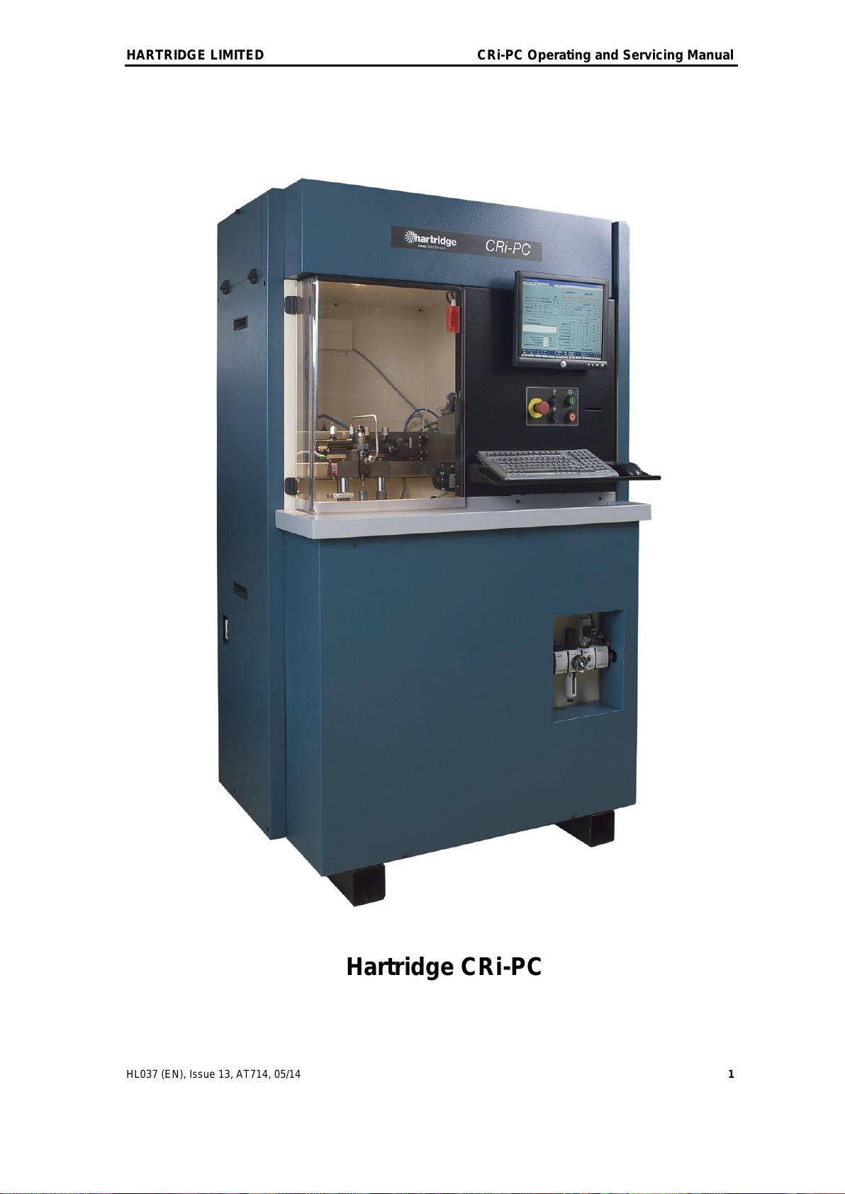
Hartridge CRi-PC
THIS IS AN UNCONTROLLED DOCUMENT downloaded by Lukas Matuska on 16 Feb 2016
Any technical intervention requires certified Hartridge training. Contact Hartridge Ltd for details.

CRi-PC Operating and Servicing Manual HARTRIDGE LIMITED
2 HL037 (EN), Issue 13, AT714, 05/14
This page intentionally left blank
THIS IS AN UNCONTROLLED DOCUMENT downloaded by Lukas Matuska on 16 Feb 2016
Any technical intervention requires certified Hartridge training. Contact Hartridge Ltd for details.
HARTRIDGE LIMITED CRi-PC Operating and Servicing Manual
HL037 (EN), Issue 13, AT714, 05/14 3
CONTENTS
FOREWORD.........................................................................................................................................................5
1. INTRODUCTION.........................................................................................................................................9
1.1 SPECIFICATION.........................................................................................................................................9
1.2 DEFINITION OF TERMS AND ABBREVIATIONS...........................................................................................9
2. INSTALLATION........................................................................................................................................11
2.1 SITE REQUIREMENTS ..............................................................................................................................11
2.2 INSTALLING THE TEST STAND.................................................................................................................11
2.3 REFIT COMPUTER ...................................................................................................................................11
2.3.1 Computer installation.....................................................................................................................11
2.4 WATER &AIR CONNECTION...................................................................................................................13
2.5 OIL &WATER DRAINAGE .......................................................................................................................13
2.6 ELECTRICAL CONNECTION .....................................................................................................................15
2.6.1 3 phase connection .........................................................................................................................15
2.6.2 Single phase connection .................................................................................................................15
2.6.3 Setting for the correct supply voltage.............................................................................................16
2.7 TEST OIL ................................................................................................................................................17
2.8 INITIAL POWER-UP.................................................................................................................................19
3. SYSTEMS AND PRINCIPLE OF OPERATION....................................................................................21
3.1 CR INJECTOR OPERATION......................................................................................................................21
3.2 INJECTOR VALVE TYPES ........................................................................................................................21
3.2.1 Solenoid Valves ..............................................................................................................................21
3.2.2 Piezo Valves....................................................................................................................................22
3.3 PNEUMATIC SYSTEM..............................................................................................................................23
3.4 FLUID SYSTEM.......................................................................................................................................23
3.5 TEMPERATURE CONTROL.......................................................................................................................23
3.6 INJECTOR AND CR PUMP CONTROL .......................................................................................................24
3.6.1 Injector control...............................................................................................................................24
3.6.2 CR pump control.............................................................................................................................24
3.7 DELIVERY &FLOW MEASUREMENT ......................................................................................................24
3.7.1 Injector delivery..............................................................................................................................24
3.7.2 Backleak flow..................................................................................................................................24
3.8 CONTROLS .............................................................................................................................................25
3.9 CIRCUITS................................................................................................................................................26
4. OPERATION ..............................................................................................................................................71
4.1 RECOMMENDED TEST SEQUENCE ..........................................................................................................71
4.2 SOFTWARE OVERVIEW...........................................................................................................................72
4.2.1 Function keys (Main Menu)............................................................................................................72
4.2.2 Function keys (Alternate Menu) .....................................................................................................73
4.2.3 Main Screen Areas .........................................................................................................................73
4.2.4 Status/Diagnostic Screen................................................................................................................74
4.2.5 Red Status Indicator .......................................................................................................................77
4.3 TEST SETUP AND METHOD.....................................................................................................................77
4.3.1 Load a Testplan..............................................................................................................................77
4.3.2 Measure Injector Coil Resistance (if selected in the ‘Start Test’ dialog). ......................................78
4.3.3 Install Injector in the Clamping Fixture & Clamp .........................................................................79
4.3.4 Start the CR pump ..........................................................................................................................81
4.3.5 Run the Test Steps...........................................................................................................................81
4.3.6 Injector removal .............................................................................................................................82
4.4 INTERPRETATION OF RESULTS ...............................................................................................................82
4.4.1 Response Time................................................................................................................................82
4.4.2 Delivery ..........................................................................................................................................82
THIS IS AN UNCONTROLLED DOCUMENT downloaded by Lukas Matuska on 16 Feb 2016
Any technical intervention requires certified Hartridge training. Contact Hartridge Ltd for details.

CRi-PC Operating and Servicing Manual HARTRIDGE LIMITED
4 HL037 (EN), Issue 13, AT714, 05/14
4.4.3 Backleakage................................................................................................................................... 82
4.4.4 Summary........................................................................................................................................ 83
4.5 CREATING/EDITING/SAVING TESTPLANS .............................................................................................. 84
4.5.1 General.......................................................................................................................................... 84
4.5.2 Parameters..................................................................................................................................... 84
4.6 VIEWING AND PRINTING SAVED RESULTS............................................................................................. 87
5. CALIBRATION AND MAINTENANCE................................................................................................ 89
5.1 CALIBRATION &AUDIT ........................................................................................................................ 89
5.2 REMOVING ACCESS PANELS ................................................................................................................. 89
5.3 REGULAR MAINTENANCE ..................................................................................................................... 92
5.3.1 Check Emergency stop................................................................................................................... 92
5.3.2 Check pressure dump valve ........................................................................................................... 93
5.3.3 Generally Clean............................................................................................................................. 93
5.3.4 Metering Audit Tests...................................................................................................................... 94
5.3.5 Backleak Audit With Magmah v9.01 onwards (If optional backleak measurement unit is fitted).. 96
5.3.6 Change test fluid & filter, clean magnet filter ............................................................................... 98
5.3.7 Change metering filter (Hartridge Number 8850073)................................................................. 101
5.4 TROUBLESHOOTING ............................................................................................................................ 102
5.4.1 General........................................................................................................................................ 102
5.4.2 Computer / monitor...................................................................................................................... 103
5.4.3 Fault indicators ........................................................................................................................... 104
5.4.4 Injector control............................................................................................................................ 106
5.4.5 CR pump control.......................................................................................................................... 107
6. SPARES .................................................................................................................................................... 109
6.1 CONSUMABLES ................................................................................................................................... 109
6.2 GENERAL SPARES ............................................................................................................................... 111
7. APPENDICES.......................................................................................................................................... 113
THIS IS AN UNCONTROLLED DOCUMENT downloaded by Lukas Matuska on 16 Feb 2016
Any technical intervention requires certified Hartridge training. Contact Hartridge Ltd for details.
HARTRIDGE LIMITED CRi-PC Operating and Servicing Manual
HL037 (EN), Issue 13, AT714, 05/14 5
Foreword
Copyright
Hartridge™ Ltd. reserves the copyright of all information and illustrations in this publication which is
supplied in confidence and which may not be used for any other purpose other than that for which it
was originally supplied. The publication may not be reproduced in part or in whole without the
consent in writing of this company.
© Hartridge Ltd.
Safety Information
Warnings, Cautions and Notes
The precautionary notes in this publication, indicated by the words WARNING, CAUTION, or NOTE
provide information about potential hazards to personnel or equipment. Ignoring these notes may
lead to serious injury to personnel and/or damage to equipment. These notes appear as follows:
WARNING! INDICATES THAT A SITUATION MAY BE HAZARDOUS TO PERSONNEL.
INSTRUCTIONS ARE PROVIDED FOR AVOIDING PERSONAL INJURY.
CAUTION! Indicates that conditions exist that could result in damage to equipment.
Instructions are provided to prevent equipment damage.
NOTE Indicates additional information for clarification where there may be confusion.
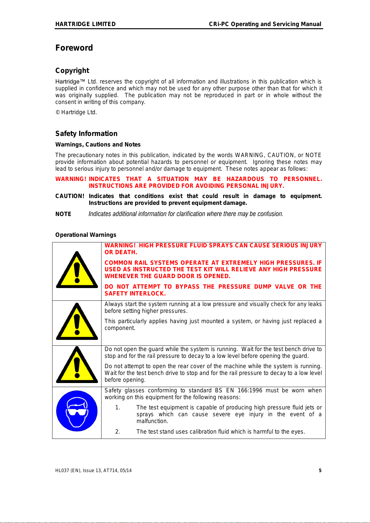
Operational Warnings
WARNING! HIGH PRESSURE FLUID SPRAYS CAN CAUSE SERIOUS INJURY
OR DEATH.
COMMON RAIL SYSTEMS OPERATE AT EXTREMELY HIGH PRESSURES. IF
USED AS INSTRUCTED THE TEST KIT WILL RELIEVE ANY HIGH PRESSURE
WHENEVER THE GUARD DOOR IS OPENED.
DO NOT ATTEMPT TO BYPASS THE PRESSURE DUMP VALVE OR THE
SAFETY INTERLOCK.
Always start the system running at a low pressure and visually check for any leaks
before setting higher pressures.
This particularly applies having just mounted a system, or having just replaced a
component.
Do not open the guard while the system is running. Wait for the test bench drive to
stop and for the rail pressure to decay to a low level before opening the guard.
Do not attempt to open the rear cover of the machine while the system is running.
Wait for the test bench drive to stop and for the rail pressure to decay to a low level
before opening.
Safety glasses conforming to standard BS EN 166:1996 must be worn when
working on this equipment for the following reasons:
1. The test equipment is capable of producing high pressure fluid jets or
sprays which can cause severe eye injury in the event of a
malfunction.
2. The test stand uses calibration fluid which is harmful to the eyes.
THIS IS AN UNCONTROLLED DOCUMENT downloaded by Lukas Matuska on 16 Feb 2016
Any technical intervention requires certified Hartridge training. Contact Hartridge Ltd for details.
CRi-PC Operating and Servicing Manual HARTRIDGE LIMITED
6 HL037 (EN), Issue 13, AT714, 05/14
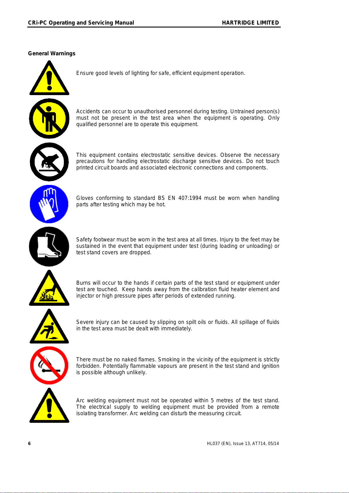
General Warnings
Ensure good levels of lighting for safe, efficient equipment operation.
Accidents can occur to unauthorised personnel during testing. Untrained person(s)
must not be present in the test area when the equipment is operating. Only
qualified personnel are to operate this equipment.
This equipment contains electrostatic sensitive devices. Observe the necessary
precautions for handling electrostatic discharge sensitive devices. Do not touch
printed circuit boards and associated electronic connections and components.
Gloves conforming to standard BS EN 407:1994 must be worn when handling
parts after testing which may be hot.
Safety footwear must be worn in the test area at all times. Injury to the feet may be
sustained in the event that equipment under test (during loading or unloading) or
test stand covers are dropped.
Burns will occur to the hands if certain parts of the test stand or equipment under
test are touched. Keep hands away from the calibration fluid heater element and
injector or high pressure pipes after periods of extended running.
Severe injury can be caused by slipping on spilt oils or fluids. All spillage of fluids
in the test area must be dealt with immediately.
There must be no naked flames. Smoking in the vicinity of the equipment is strictly
forbidden. Potentially flammable vapours are present in the test stand and ignition
is possible although unlikely.
Arc welding equipment must not be operated within 5 metres of the test stand.
The electrical supply to welding equipment must be provided from a remote
isolating transformer. Arc welding can disturb the measuring circuit.
THIS IS AN UNCONTROLLED DOCUMENT downloaded by Lukas Matuska on 16 Feb 2016
Any technical intervention requires certified Hartridge training. Contact Hartridge Ltd for details.
HARTRIDGE LIMITED CRi-PC Operating and Servicing Manual
HL037 (EN), Issue 13, AT714, 05/14 7
Ensure that the servicing requirements and intervals as set out in the Maintenance
section are adhered to. Operate and service this equipment only if competent to
do so. Carry out regular inspections to make sure all high pressure connections
are tight and safe.
High fluid pressures exist within the test stand. Do not run the test stand without
all cover panels fitted.
Fluid sprays, especially from leaking high pressure pipes and seals, will cause
high pressure injection through the skin which can result in fatal injury.
Use calibration fluid and lube oil of the correct specification only. Obtain the
manufacturers Health & Safety Data Sheets and follow the advice given therein.
Prolonged and repeated contact with oil products, ingestion or excessive and
prolonged inhalation of oil mists can be detrimental to health. Use an appropriate
barrier cream.
Make sure there is adequate ventilation. Oil vapour may be released from hot
fixtures or high pressure leaks. The specific directions in Health & Safety Data
Sheets must be adhered to.
High Voltage!
Isolate and lock the electrical supply off before performing any maintenance
operations. Do not work on electrical equipment while voltage is supplied.
Be aware that the computer and monitor are supplied separately from the test
stand 3 phase supply and may therefore still be powered when the test stand 3
phase supply is switched off.
THIS IS AN UNCONTROLLED DOCUMENT downloaded by Lukas Matuska on 16 Feb 2016
Any technical intervention requires certified Hartridge training. Contact Hartridge Ltd for details.

CRi-PC Operating and Servicing Manual HARTRIDGE LIMITED
8 HL037 (EN), Issue 13, AT714, 05/14
This page intentionally left blank
THIS IS AN UNCONTROLLED DOCUMENT downloaded by Lukas Matuska on 16 Feb 2016
Any technical intervention requires certified Hartridge training. Contact Hartridge Ltd for details.
HARTRIDGE LIMITED CRi-PC Operating and Servicing Manual
HL037 (EN), Issue 13, AT714, 05/14 9
1. Introduction
The Common Rail Injector Test Stand (CRi-PC) is designed to enable testing of Common Rail
injectors. The stand accommodates currently available injectors from Bosch, Delphi, Denso
and Siemens. Fixture components are available for testing specific injector types.
The test stand incorporates semi-automatic injector clamping.
An interlocked safety door furnished with a 10mm clear PETg shield protects the operator
from the high pressures generated in common rail systems.
Injectors may be tested in manual or automatic mode by pre-configured testplans created in
the Hartridge™ Magmah software. Injector control is via AE32 based hardware.
Injector delivery measurement is based on the Hartridge™ AVM2 Positive Displacement
Metering Unit & Metering Control Board. Injector backleak flow is measured by an HK901 or
HK901-P based system.
1.1 Specification
Injector Control Features Single channel injector drive circuit, suitable for current
Bosch, Delphi & Denso solenoid injectors and Siemens piezo
injectors.
Injector Measurements Single channel solenoid resistance measurement.
Single channel response time measurement.
Backleak flow and temperature measurement.
Injector delivery measurement within ±0.5% of reading.
Test Fluid Supply System Tank capacity 43 litres nominal (40l. main tank, 3l. clean
tank)
Oil pump
Filter
Over-temperature thermostat
Low fluid level protection (main and clean tanks).
Level indicator and drain pipe.
Sludge and magnetic particle traps.
Temperature control ±2°C using electric heater and water /
oil heat exchangers.
1.2 Definition of Terms and Abbreviations
CR Common rail
CRIB Common rail injector (control) board
FCV Flow control valve
I/P Input
IPM Injections per minute
LED Light emitting diode
MAGMAH Hartridge™ PC control software
MCB4 Metering control board 4
O/P Output
PC IBM compatible computer
PCB Printed circuit board
PCV Pressure control valve
PLC Programmable logic controller
VCV Volume control valve
RS232 Serial communications
S/W Software
UUT Unit under test
THIS IS AN UNCONTROLLED DOCUMENT downloaded by Lukas Matuska on 16 Feb 2016
Any technical intervention requires certified Hartridge training. Contact Hartridge Ltd for details.

CRi-PC Operating and Servicing Manual HARTRIDGE LIMITED
10 HL037 (EN), Issue 13, AT714, 05/14
This page intentionally left blank
THIS IS AN UNCONTROLLED DOCUMENT downloaded by Lukas Matuska on 16 Feb 2016
Any technical intervention requires certified Hartridge training. Contact Hartridge Ltd for details.
HARTRIDGE LIMITED CRi-PC Operating and Servicing Manual
HL037 (EN), Issue 13, AT714, 05/14 11
2. Installation
2.1 Site requirements
Allow 1 metre around the front and sides of the test stand for access. The rear of the test
stand should allow adequate space for the electrical, air and water connections.
The site must have a clean level floor capable of supporting the test stand weight.
Supply of clean water at 20°C maximum, with a nominal flow available of 5 litres/min. -
minimum pressure 2.5 bar (40 psi). The minimum water temperature should be 10°C, if
the water temperature is too low condensation may occur on the water pipes inside the
machine.
The site should be well ventilated to dissipate heat and test oil vapour.
Supply of clean, dry pressurised air - minimum pressure 6.5 bar (95 psi).
Electrical Supply:
3 Phase and Earth 380-480V ± 6%, 50 Hz, fused at 25A
3 Phase and Earth 200-260V ± 6%, 60 Hz, fused at 35A.
Lift the test stand from underneath using a fork lift placed under the test stand base.
The dry weight of the test stand is approximately 400 kg.
2.2 Installing the test stand
The test stand must be levelled in both horizontal planes before use.
1. Position the test stand on the rubber feet supplied.
2. Place a spirit level on the top of the test stand.
3. If the test stand is not level place metal shims between the machine and the rubber feet
as required to achieve support on all four feet, checking the level in both horizontal
planes.
2.3 Refit computer
2.3.1 Computer installation
Refer to Figure 2.1.
1. Remove all packaging and strapping from the test bench.
2. Locate the PC mounting tray into the upper compartment (1) with foam feet down and the
larger foam foot on the right and nearest the outside of the machine. Mount the computer
onto the tray. The computer should be located to allow access to the CDROM and power
switch through the hinged panel (2).
3. Feed the keyboard and mouse cables through the holes in the keyboard tray and facia
panel (3), then up into the PC area.
4. Reconnect the cables at the rear of the computer, typically -
Power
Monitor
USB Mouse
USB Keyboard
Serial port 1 (cable 77)
Serial port 2 for optional printer (if fitted)
Serial port 3 (cable 51)
Serial port 4 (cable 50)
5. Connect the power cables of the computer and the printer (optional) to the power
distribution block (4).
THIS IS AN UNCONTROLLED DOCUMENT downloaded by Lukas Matuska on 16 Feb 2016
Any technical intervention requires certified Hartridge training. Contact Hartridge Ltd for details.

CRi-PC Operating and Servicing Manual HARTRIDGE LIMITED
12 HL037 (EN), Issue 13, AT714, 05/14
6. Ensure that the computer power supply voltage switch (5) is set in the correct position for
the electrical supply of the end user (if applicable).
Figure 2.1 Fitting the Computer
1
2
4
3
5
THIS IS AN UNCONTROLLED DOCUMENT downloaded by Lukas Matuska on 16 Feb 2016
Any technical intervention requires certified Hartridge training. Contact Hartridge Ltd for details.

HARTRIDGE LIMITED CRi-PC Operating and Servicing Manual
HL037 (EN), Issue 13, AT714, 05/14 13
2.4 Water & air connection
Refer to Figure 2.2.
Connect the water IN (supply) pipe to the 10mm bulkhead fitting (1).
Connect the water OUT (return) pipe to the 10mm bulkhead fitting (2).
Connect the air supply pipe to the supplied plug (¼” Gas female thread) (3).
Figure 2.2 Water & Air Connections
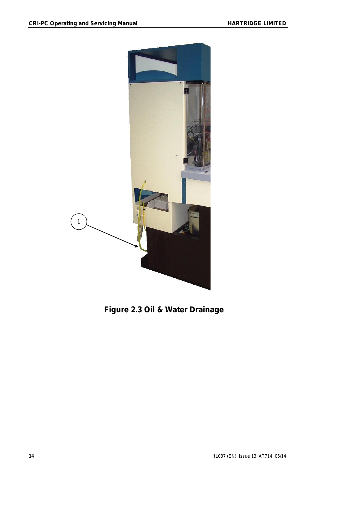
2.5 Oil & water drainage
Refer to Figure 2.3
The yellow pipe (1) on the left of the machine, visible when the left side panel is removed,
carries oil and water leakage from the high pressure pump/motor tray to prevent
contamination of the oil in the main tank.
This pipe must be routed to the back of the machine as shown and the fluid collected in a tray
for safe disposal. Ensure the pipe is not trapped by the side cover when it is refitted.
2
3
1
THIS IS AN UNCONTROLLED DOCUMENT downloaded by Lukas Matuska on 16 Feb 2016
Any technical intervention requires certified Hartridge training. Contact Hartridge Ltd for details.
CRi-PC Operating and Servicing Manual HARTRIDGE LIMITED
14 HL037 (EN), Issue 13, AT714, 05/14
Figure 2.3 Oil & Water Drainage
1
THIS IS AN UNCONTROLLED DOCUMENT downloaded by Lukas Matuska on 16 Feb 2016
Any technical intervention requires certified Hartridge training. Contact Hartridge Ltd for details.

HARTRIDGE LIMITED CRi-PC Operating and Servicing Manual
HL037 (EN), Issue 13, AT714, 05/14 15
2.6 Electrical connection
The connection of electrical supplies must comply with the local and national electrical
regulations. Make sure the connection of 3 phase electrical power is carried out by a suitably
qualified electrician.
WARNING
The equipment must be hardwired and bonded to a protective earth
system before the mains supply wires are connected. The earth wire
must be taken directly to earth instead of or as well as through a plug
and socket.
Failure to earth the test stand before applying mains power can cause a
fatal electric shock.
CAUTION
The Common Rail Pump motor used on the test stand is phase rotation sensitive.
Correct rotation of the motor is essential to prevent damage to the Common Rail
pump. This can be checked by following the procedure given in Section 2.7.
2.6.1 3 phase connection
Refer to Figure 2.4
1. Ensure the test stand isolator and incoming supply isolator switches are off.
2. Open the electrical cabinet door.
3. Feed the 3 phase and Earth wires from the main electrical supply through the hole (1)
located at the rear of the cabinet.
4. Connect each phase to the isolator switch (2).
5. Connect the Earth wire to the earth terminal (3).
2.6.2 Single phase connection
1. Using a suitable power cable terminated with a standard IEC socket. Connect the single
phase supply to the test stand at the IEC plug located on the rear of the cabinet.
2. Ensure the connector retaining clip (4) is in place.
Figure 2.4 Electrical Connections
1
4
2
3
THIS IS AN UNCONTROLLED DOCUMENT downloaded by Lukas Matuska on 16 Feb 2016
Any technical intervention requires certified Hartridge training. Contact Hartridge Ltd for details.

CRi-PC Operating and Servicing Manual HARTRIDGE LIMITED
16 HL037 (EN), Issue 13, AT714, 05/14
2.6.3 Setting for the correct supply voltage
Refer to Figure 2.5
These settings should have been done before shipment, however it is possible that the
customer’s local supply is different to the standard national supply system.
1. Transformer supply setting.
The primary tapping on the transformer needs to be set to match the voltage of the
customer’s incoming supply. This involves connecting the wires identified as 210 (1) &
310 (2) to the correct terminal studs on the transformer.
Customer
Voltage Supply
Wire 210
transformer stud
Wire 310
transformer stud
190V-209V
220V
20V
(220 –20 = 200V)
210V-229V
220V
0V
(220 –0 = 220V)
230V-249V
220V
-20V
(220 + 20 = 240V)
250V-270V
260V
0V
(260 –0 = 260V)
370V-389V
400V
20V
(400 –20 = 380V)
390V-410V
400V
0V
(400 –0 = 400V)
411V-419V
415V
0V
(415 –0 = 415V)
420V-429V
400V
-20V
(400 + 20 = 420V)
430V-449V
460V
20V
(460 –20 = 440V)
450V-469V
460V
0V
(460 –0 = 460V)
470V-490V
460V
-20V
(460 + 20 = 480V)
2. Frequency link.
A red wire link (3) is located at positions 2/3 & 4 of the large terminal strip on the electrics
chassis.
If the voltage supply frequency is 50Hz, the link must be wired between terminals 2and 3.
If the voltage supply frequency is 60Hz, the link must be wired between terminals 3and 4.
Figure 2.5 Supply Settings
2
1
3
THIS IS AN UNCONTROLLED DOCUMENT downloaded by Lukas Matuska on 16 Feb 2016
Any technical intervention requires certified Hartridge training. Contact Hartridge Ltd for details.
HARTRIDGE LIMITED CRi-PC Operating and Servicing Manual
HL037 (EN), Issue 13, AT714, 05/14 17
2.7 Test oil
Refer to Figure 2.6
WARNING! HIGH PRESSURE FLUID SPRAYS CAN CAUSE
SERIOUS INJURY OR DEATH. COMMON RAIL SYSTEMS OPERATE
AT EXTREMELY HIGH PRESSURES.
DO NOT ATTEMPT TO OPEN THE TANK ACCESS PANEL WHILE
THE SYSTEM IS RUNNING.
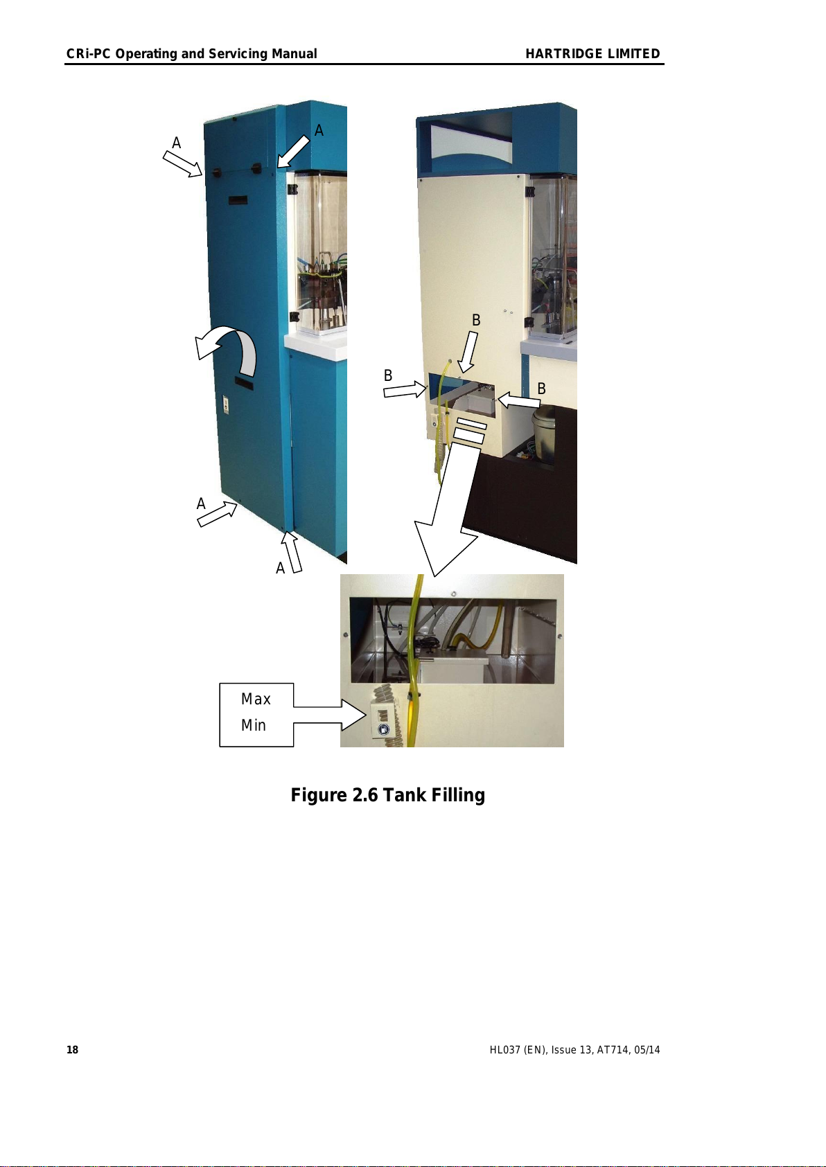
The tank should be filled via the left side panel.
Loosen the four panel retaining screws (A) and lift off the side panel.
Remove the three panel retaining nuts (B) and lift off the tank access panel.
Fill the tank with clean test fluid to Shell ISO 4113 specification through the aperture in the
side of the test stand.
The fill level can be observed on the tank drain tube on the bracket below the tank access
aperture. The window indicates the maximum & minimum levels and is also visible when all
panels have been replaced.
Replace the tank access panel and the left side panel.
THIS IS AN UNCONTROLLED DOCUMENT downloaded by Lukas Matuska on 16 Feb 2016
Any technical intervention requires certified Hartridge training. Contact Hartridge Ltd for details.
CRi-PC Operating and Servicing Manual HARTRIDGE LIMITED
18 HL037 (EN), Issue 13, AT714, 05/14
Figure 2.6 Tank Filling
Max
Min
A
A
B
A
A
B
B
THIS IS AN UNCONTROLLED DOCUMENT downloaded by Lukas Matuska on 16 Feb 2016
Any technical intervention requires certified Hartridge training. Contact Hartridge Ltd for details.
Table of contents
Other Hartridge Test Equipment manuals


Popular Test Equipment manuals by other brands


Kyoritsu Electrical Instruments Works, Ltd.
Kyoritsu Electrical Instruments Works, Ltd. 6050 instruction manual

Unit
Unit UT2000 series user manual

WABCO WÜRTH
WABCO WÜRTH W.EASY ADAS Calibration manual

AU Tool
AU Tool CT180 user manual

Thomas&Betts
Thomas&Betts Elastimold 168DRG operating instructions

B+K precision
B+K precision 8500B Series user manual