Hartridge HK900 User manual
HL030(EN), Issue 1, June 2005
World Leaders in Diesel Fuel Injection Test Equipment
HK900
All Makes Common Rail
Injector Test Kit (AVM2)
Operating Manual
THIS IS AN UNCONTROLLED DOCUMENT downloaded by Lukas Matuska on 16 Feb 2016
Any technical intervention requires certified Hartridge training. Contact Hartridge Ltd for details.

THIS IS AN UNCONTROLLED DOCUMENT downloaded by Lukas Matuska on 16 Feb 2016
Any technical intervention requires certified Hartridge training. Contact Hartridge Ltd for details.

HARTRIDGE LIMITED Operating Manual
HL030(EN), Issue 1, June 2005 1
CONTENTS
FOREWORD.........................................................................................................................................................3
1. INTRODUCTION.........................................................................................................................................7
1.1 SPECIFICATION...............................................................................................................................................7
1.2 RELATED DOCUMENTS...................................................................................................................................7
1.3 DEFINITION OF TERMS AND ABBREVIATIONS.................................................................................................7
2. INSTALLATION..........................................................................................................................................9
2.1 FIXTURE INSTALLATION AND HYDRAULIC CONNECTIONS .............................................................................9
2.2 UPGRADE TO AE31 PUMP CONTROL UNIT...................................................................................................10
2.3 INJECTOR CONTROL UNIT ............................................................................................................................10
2.3.1 Fitting/Installation ...............................................................................................................................10
2.4 ACCESSORY STORAGE..................................................................................................................................14
3. INTRODUCTION TO CR INJECTORS .................................................................................................15
3.1 CR INJECTOR OPERATION............................................................................................................................15
3.2 INJECTOR VALVE TYPES ..............................................................................................................................15
3.2.1 Solenoid Valves....................................................................................................................................15
3.2.2 Piezo Valves.........................................................................................................................................16
3.3 RECOMMENDED TEST SEQUENCE.................................................................................................................16
4. OPERATION ..............................................................................................................................................17
4.1 GUIDELINES FOR SAFE WORKING PRACTICE................................................................................................17
4.2 SOFTWARE OVERVIEW.................................................................................................................................17
4.3 TEST SETUP AND METHOD...........................................................................................................................19
4.3.1 Fit the Surrogate Pump........................................................................................................................19
4.3.2 Load a Testplan....................................................................................................................................19
4.3.3 Measure Injector Coil Resistance ........................................................................................................20
4.3.4 Install Injectors in the Fixture..............................................................................................................20
4.3.5 Run the Test Steps ................................................................................................................................21
4.3.6 End of Test ...........................................................................................................................................22
4.4 INTERPRETATION OF RESULTS .....................................................................................................................22
4.4.1 Response Time......................................................................................................................................22
4.4.2 Delivery................................................................................................................................................23
4.4.3 Backleakage (with HK901) ..................................................................................................................23
4.4.4 Summary...............................................................................................................................................23
4.5 CREATING/EDITING/SAVING TESTPLANS .....................................................................................................23
4.6 VIEWING AND PRINTING SAVED RESULTS....................................................................................................24
5. MAINTENANCE........................................................................................................................................25
5.1 REGULAR MAINTENANCE ............................................................................................................................25
5.2 TROUBLESHOOTING .....................................................................................................................................25
5.2.1 Status Indicator Light...........................................................................................................................25
5.2.2 Other Faults.........................................................................................................................................25
6. SPARES.......................................................................................................................................................26
THIS IS AN UNCONTROLLED DOCUMENT downloaded by Lukas Matuska on 16 Feb 2016
Any technical intervention requires certified Hartridge training. Contact Hartridge Ltd for details.

Operating Manual HARTRIDGE LIMITED
2 HL030(EN), Issue 1, June 2005
This page left deliberately blank
THIS IS AN UNCONTROLLED DOCUMENT downloaded by Lukas Matuska on 16 Feb 2016
Any technical intervention requires certified Hartridge training. Contact Hartridge Ltd for details.
HARTRIDGE LIMITED Operating Manual
HL030(EN), Issue 1, June 2005 3
Foreword
Copyright
Hartridge Ltd. reserves the copyright of all information and illustrations in this publication which is
supplied in confidence and which may not be used for any other purpose other than that for which it
was originally supplied. The publication may not be reproduced in part or in whole without the consent
in writing of this company.
© Hartridge Ltd.
Safety Information
Warnings, Cautions and Notes
The precautionary notes in this publication, indicated by the words WARNING, CAUTION, or NOTE
provide information about potential hazards to personnel or equipment. Ignoring these notes may
lead to serious injury to personnel and/or damage to equipment. These notes appear as follows:
WARNING! INDICATES THAT A SITUATION MAY BE HAZARDOUS TO PERSONNEL.
INSTRUCTIONS ARE PROVIDED FOR AVOIDING PERSONAL INJURY.
CAUTION! Indicates that conditions exist that could result in damage to equipment.
Instructions are provided to prevent equipment damage.
NOTE Indicates additional information for clarification where there may be confusion.
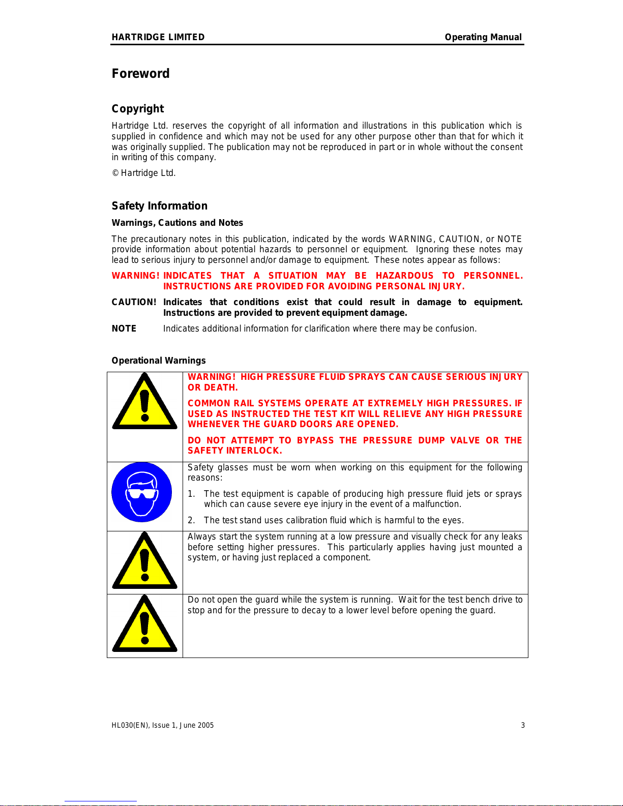
Operational Warnings
WARNING! HIGH PRESSURE FLUID SPRAYS CAN CAUSE SERIOUS INJURY
OR DEATH.
COMMON RAIL SYSTEMS OPERATE AT EXTREMELY HIGH PRESSURES. IF
USED AS INSTRUCTED THE TEST KIT WILL RELIEVE ANY HIGH PRESSURE
WHENEVER THE GUARD DOORS ARE OPENED.
DO NOT ATTEMPT TO BYPASS THE PRESSURE DUMP VALVE OR THE
SAFETY INTERLOCK.
Safety glasses must be worn when working on this equipment for the following
reasons:
1. The test equipment is capable of producing high pressure fluid jets or sprays
which can cause severe eye injury in the event of a malfunction.
2. The test stand uses calibration fluid which is harmful to the eyes.
Always start the system running at a low pressure and visually check for any leaks
before setting higher pressures. This particularly applies having just mounted a
system, or having just replaced a component.
Do not open the guard while the system is running. Wait for the test bench drive to
stop and for the pressure to decay to a lower level before opening the guard.
THIS IS AN UNCONTROLLED DOCUMENT downloaded by Lukas Matuska on 16 Feb 2016
Any technical intervention requires certified Hartridge training. Contact Hartridge Ltd for details.
Operating Manual HARTRIDGE LIMITED
4 HL030(EN), Issue 1, June 2005
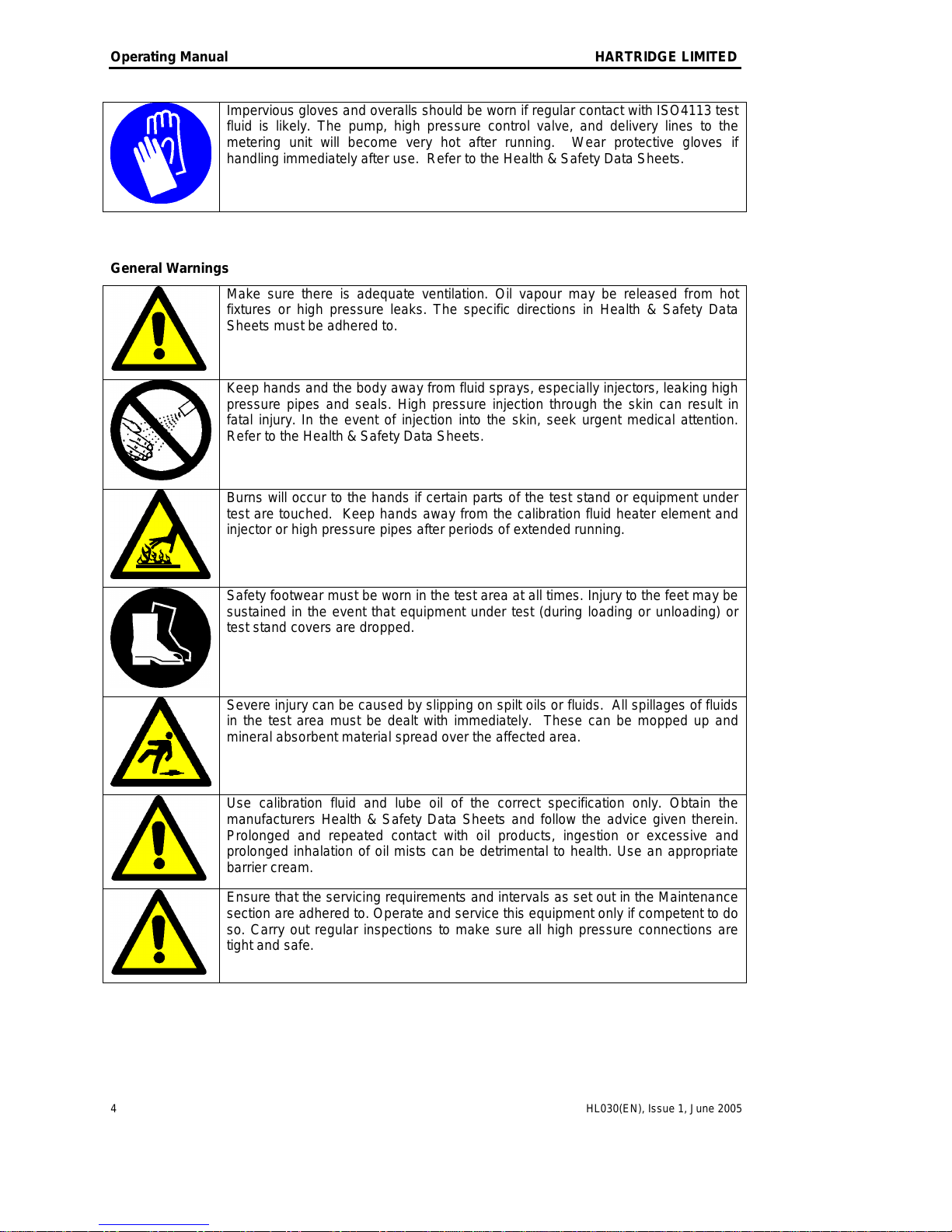
Impervious gloves and overalls should be worn if regular contact with ISO4113 test
fluid is likely. The pump, high pressure control valve, and delivery lines to the
metering unit will become very hot after running. Wear protective gloves if
handling immediately after use. Refer to the Health & Safety Data Sheets.
General Warnings
Make sure there is adequate ventilation. Oil vapour may be released from hot
fixtures or high pressure leaks. The specific directions in Health & Safety Data
Sheets must be adhered to.
Keep hands and the body away from fluid sprays, especially injectors, leaking high
pressure pipes and seals. High pressure injection through the skin can result in
fatal injury. In the event of injection into the skin, seek urgent medical attention.
Refer to the Health & Safety Data Sheets.
Burns will occur to the hands if certain parts of the test stand or equipment under
test are touched. Keep hands away from the calibration fluid heater element and
injector or high pressure pipes after periods of extended running.
Safety footwear must be worn in the test area at all times. Injury to the feet may be
sustained in the event that equipment under test (during loading or unloading) or
test stand covers are dropped.
Severe injury can be caused by slipping on spilt oils or fluids. All spillages of fluids
in the test area must be dealt with immediately. These can be mopped up and
mineral absorbent material spread over the affected area.
Use calibration fluid and lube oil of the correct specification only. Obtain the
manufacturers Health & Safety Data Sheets and follow the advice given therein.
Prolonged and repeated contact with oil products, ingestion or excessive and
prolonged inhalation of oil mists can be detrimental to health. Use an appropriate
barrier cream.
Ensure that the servicing requirements and intervals as set out in the Maintenance
section are adhered to. Operate and service this equipment only if competent to do
so. Carry out regular inspections to make sure all high pressure connections are
tight and safe.
THIS IS AN UNCONTROLLED DOCUMENT downloaded by Lukas Matuska on 16 Feb 2016
Any technical intervention requires certified Hartridge training. Contact Hartridge Ltd for details.

HARTRIDGE LIMITED Operating Manual
HL030(EN), Issue 1, June 2005 5
Remove any tools, cleaning rags or other debris from the test stand before starting
up. Make sure the inching bar is not fitted to the test stand before starting up.
There must be no naked flames. Potentially flammable vapours are present in the
test stand and ignition is possible although unlikely. Smoking whilst operating the
equipment is strictly forbidden.
Accidents can occur to unauthorised personnel during testing. Untrained person(s)
must not be present in the test area when the equipment is operating. Only
qualified personnel are to operate this equipment.
Ensure good levels of lighting for safe, efficient equipment operation.
THIS IS AN UNCONTROLLED DOCUMENT downloaded by Lukas Matuska on 16 Feb 2016
Any technical intervention requires certified Hartridge training. Contact Hartridge Ltd for details.

Operating Manual HARTRIDGE LIMITED
6 HL030(EN), Issue 1, June 2005
This page left deliberately blank
THIS IS AN UNCONTROLLED DOCUMENT downloaded by Lukas Matuska on 16 Feb 2016
Any technical intervention requires certified Hartridge training. Contact Hartridge Ltd for details.

HARTRIDGE LIMITED Operating Manual
HL030(EN), Issue 1, June 2005 7
1. Introduction
The HK900 Common Rail Injector Test Kit is designed to be fitted to the AVM2-PC Test Stand to
enable testing of Common Rail injectors. Additional mounting parts are available for testing specific
injector types.
NOTE: The AVM2-PC must be fitted with the following items in order to use the HK900 (all
available separately):
- HB378 Common Rail Base Kit
- HF1130 Common Rail Pump Test Kit
- Version 33 (or later) Magmah PC software
1.1 Specification
Refer to packing list for kit contents. The AE32 Injector Control Unit specification is as follows:
Power Supply
120/240V AC 50/60Hz Single Phase
Control Features
4-channel injector drive circuit, suitable for current Bosch, Delphi and Denso
solenoid injectors, and Siemens piezo injectors.
Measurements
Single channel solenoid resistance measurement.
4-channel response time measurement (via response time unit).
Auxiliary voltage measurement channel.
Miscellaneous
Status reporting.
Interface to HK901 for 4-line backleak flow and temperature measurement.
1.2 Related Documents
This manual describes the general operation of the HK900 kit for testing Common Rail injectors.
Bulletin TIB195/11 (also provided in this kit) outlines the accessories available and which injector
applications they cover.
Please contact Hartridge, or visit www.hartridge.com for the latest availability of accessories and
bulletins.
Users should also be familiar with the HB378 CR Base Kit manual (ref HL024), and HF1130 All
Makes CR Pump Kit manual (ref HL025).
1.3 Definition of Terms and Abbreviations
CR Common Rail
FIE Fuel Injection Equipment
PCV Pressure Control Valve
IMV Inlet Metering Valve
FCV Flow Control Valve
VCV Volume Control Valve
3rd CYL Pump 3rd Cylinder Solenoid (Bosch CP1 pumps)
PWM Pulse Width Modulation
THIS IS AN UNCONTROLLED DOCUMENT downloaded by Lukas Matuska on 16 Feb 2016
Any technical intervention requires certified Hartridge training. Contact Hartridge Ltd for details.

Operating Manual HARTRIDGE LIMITED
8 HL030(EN), Issue 1, June 2005
This page left deliberately blank
THIS IS AN UNCONTROLLED DOCUMENT downloaded by Lukas Matuska on 16 Feb 2016
Any technical intervention requires certified Hartridge training. Contact Hartridge Ltd for details.
HARTRIDGE LIMITED Operating Manual
HL030(EN), Issue 1, June 2005 9
2. Installation
SWITCH OFF POWER SUPPLIES BEFORE STARTING THE INSTALLATION
PROCEDURE.
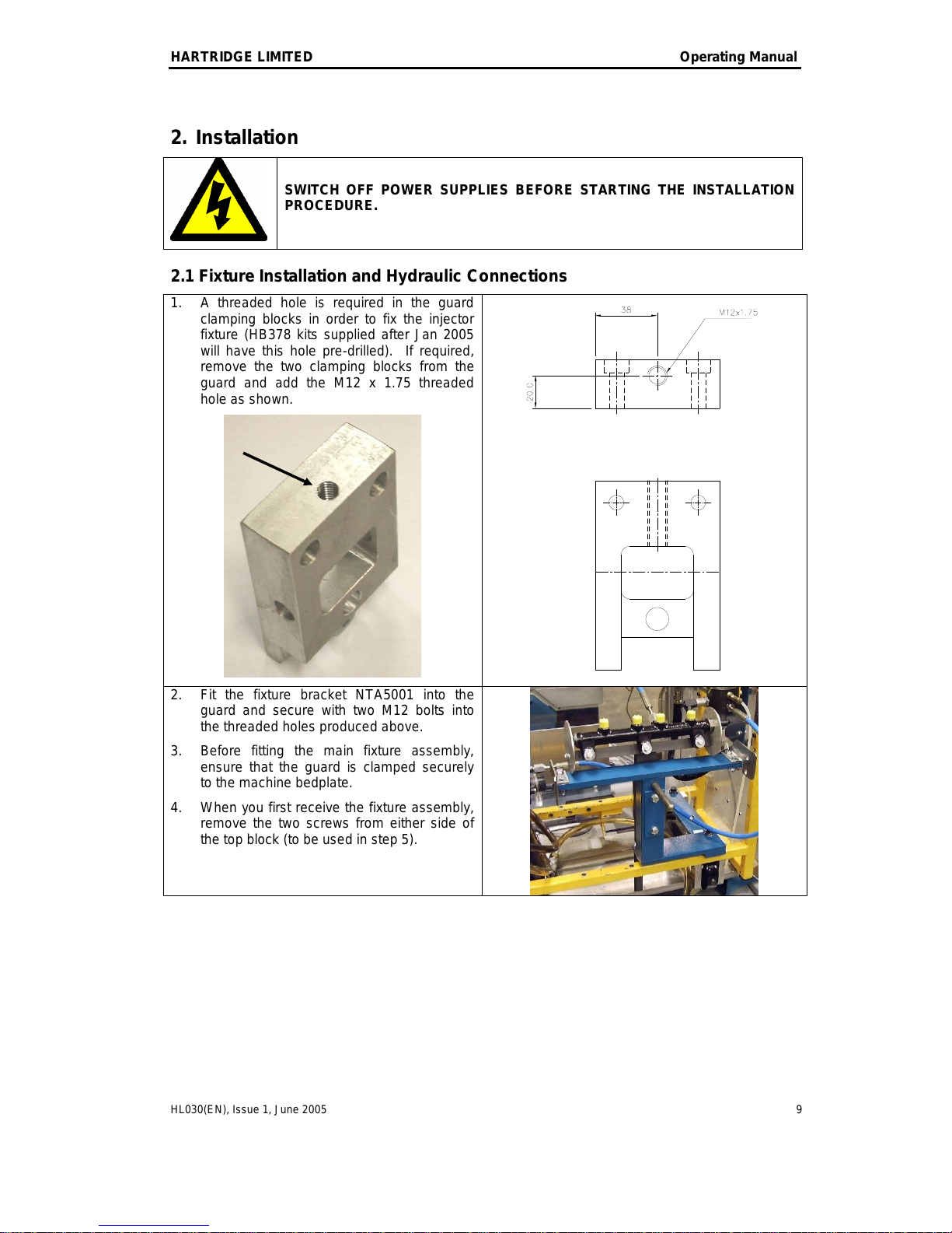
2.1 Fixture Installation and Hydraulic Connections
1. A threaded hole is required in the guard
clamping blocks in order to fix the injector
fixture (HB378 kits supplied after Jan 2005
will have this hole pre-drilled). If required,
remove the two clamping blocks from the
guard and add the M12 x 1.75 threaded
hole as shown.
2. Fit the fixture bracket NTA5001 into the
guard and secure with two M12 bolts into
the threaded holes produced above.
3. Before fitting the main fixture assembly,
ensure that the guard is clamped securely
to the machine bedplate.
4. When you first receive the fixture assembly,
remove the two screws from either side of
the top block (to be used in step 5).
THIS IS AN UNCONTROLLED DOCUMENT downloaded by Lukas Matuska on 16 Feb 2016
Any technical intervention requires certified Hartridge training. Contact Hartridge Ltd for details.
Operating Manual HARTRIDGE LIMITED
10 HL030(EN), Issue 1, June 2005
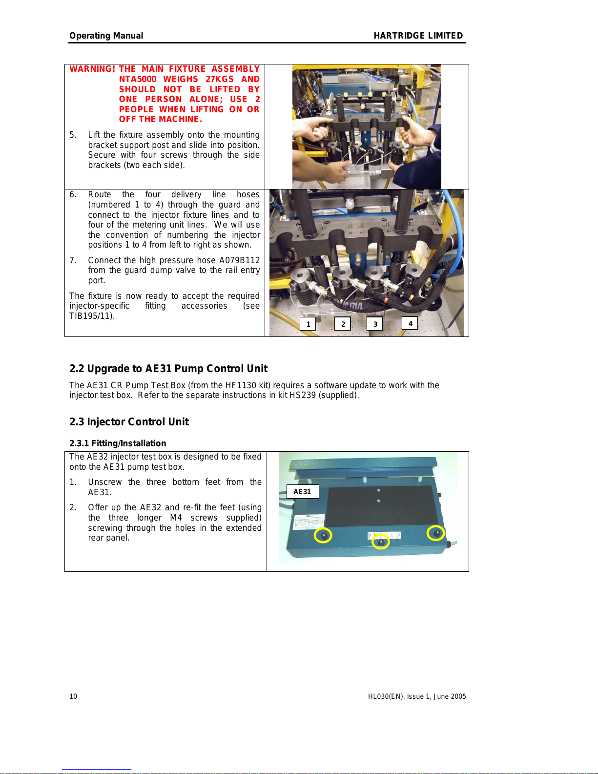
WARNING! THE MAIN FIXTURE ASSEMBLY
NTA5000 WEIGHS 27KGS AND
SHOULD NOT BE LIFTED BY
ONE PERSON ALONE; USE 2
PEOPLE WHEN LIFTING ON OR
OFF THE MACHINE.
5. Lift the fixture assembly onto the mounting
bracket support post and slide into position.
Secure with four screws through the side
brackets (two each side).
6. Route the four delivery line hoses
(numbered 1 to 4) through the guard and
connect to the injector fixture lines and to
four of the metering unit lines. We will use
the convention of numbering the injector
positions 1 to 4 from left to right as shown.
7. Connect the high pressure hose A079B112
from the guard dump valve to the rail entry
port.
The fixture is now ready to accept the required
injector-specific fitting accessories (see
TIB195/11).
2.2 Upgrade to AE31 Pump Control Unit
The AE31 CR Pump Test Box (from the HF1130 kit) requires a software update to work with the
injector test box. Refer to the separate instructions in kit HS239 (supplied).
2.3 Injector Control Unit
2.3.1 Fitting/Installation
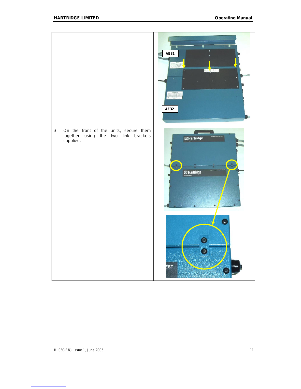
The AE32 injector test box is designed to be fixed
onto the AE31 pump test box.
1. Unscrew the three bottom feet from the
AE31.
2. Offer up the AE32 and re-fit the feet (using
the three longer M4 screws supplied)
screwing through the holes in the extended
rear panel.
1
2
3
4
AE31
THIS IS AN UNCONTROLLED DOCUMENT downloaded by Lukas Matuska on 16 Feb 2016
Any technical intervention requires certified Hartridge training. Contact Hartridge Ltd for details.
HARTRIDGE LIMITED Operating Manual
HL030(EN), Issue 1, June 2005 11
3. On the front of the units, secure them
together using the two link brackets
supplied.
AE31
AE32
THIS IS AN UNCONTROLLED DOCUMENT downloaded by Lukas Matuska on 16 Feb 2016
Any technical intervention requires certified Hartridge training. Contact Hartridge Ltd for details.

Operating Manual HARTRIDGE LIMITED
12 HL030(EN), Issue 1, June 2005
2.3.2 Connections
The features on the left hand side of the box are as follows:
1. Power/status indicator light (see section 5.2.1).
2. Power switch.
3. Connection for Injector cable.
4. Connection for Resistance measurement cable.
5. Connection for HK901 Backleak Unit, and two status
indicator lights (these indicate the backleak unit status and will
be explained in the HK901 manual).
6. Auxiliary 5V output and measurement channel (spare –for
future use).
7. Flying lead for connection to the response time box (on
fixture NTA5000).
Figure 2.2: Box Features (Left)
The features on the right hand side of the box are as follows:
8. Flying lead for connection to AE31.
9. Connection for communications loom A089E956 (to avoid
confusion with the AE31 this loom has a RED D connector)
10. Push button for HK901 Backleak Unit diagnostics.
11. Single Phase power socket with 5A fuse, and voltage
selector switch.
Figure 2.3: Box Features (Right)
THIS IS AN UNCONTROLLED DOCUMENT downloaded by Lukas Matuska on 16 Feb 2016
Any technical intervention requires certified Hartridge training. Contact Hartridge Ltd for details.

HARTRIDGE LIMITED Operating Manual
HL030(EN), Issue 1, June 2005 13
Once the AE31 and AE32 boxes have been fitted together, hang on the right hand side of the test
bench and connect as follows (the numbers in brackets refer to Figures 2.2 and 2.3 above):
CAUTION! The voltage selector switch must be set to the correct setting for your local single
phase voltage (120/240V).
1. Set the voltage selector switch (11) to the correct value then plug in the single phase power lead.
2. Connect flying lead (8) to the spare socket on the right hand side of the AE31 unit.
3. Connect the red D plug on loom A089E956 to socket (9) on the AE32. Plug the other end of this
loom into EXT2 on the rear of the AVM2. Plug the AE31 comms loom A086E913 into the spare
flying socket on this new loom.
4. Connect the flying lead (7) to the response time unit on the fixture.
You are now ready to connect the main injector drive lead to socket (3) and the resistance cable to
socket (4). These cables will depend on the injector type you are testing; see TIB195/11.
THIS IS AN UNCONTROLLED DOCUMENT downloaded by Lukas Matuska on 16 Feb 2016
Any technical intervention requires certified Hartridge training. Contact Hartridge Ltd for details.
Operating Manual HARTRIDGE LIMITED
14 HL030(EN), Issue 1, June 2005
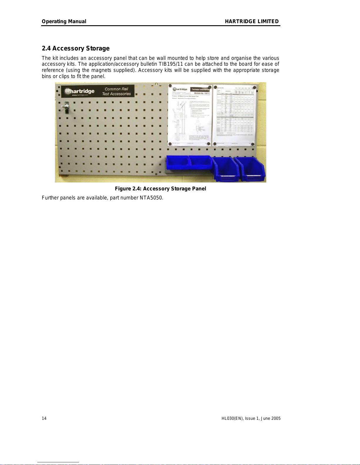
2.4 Accessory Storage
The kit includes an accessory panel that can be wall mounted to help store and organise the various
accessory kits. The application/accessory bulletin TIB195/11 can be attached to the board for ease of
reference (using the magnets supplied). Accessory kits will be supplied with the appropriate storage
bins or clips to fit the panel.
Figure 2.4: Accessory Storage Panel
Further panels are available, part number NTA5050.
THIS IS AN UNCONTROLLED DOCUMENT downloaded by Lukas Matuska on 16 Feb 2016
Any technical intervention requires certified Hartridge training. Contact Hartridge Ltd for details.

HARTRIDGE LIMITED Operating Manual
HL030(EN), Issue 1, June 2005 15
3. Introduction to CR Injectors
3.1 CR Injector Operation
One of the main differences between Common Rail injectors and traditional mechanical injectors is
the introduction of electrical control; with Common Rail injectors the timing and duration of injection
are controlled using an electrically-operated valve. There are currently two types of valve, described
in section 3.2 below.
In terms of the hydraulic operation, high pressure fuel is supplied to the nozzle body and to a chamber
on top of the control needle. The electrical valve opens/closes a leak off path from this chamber into
the return circuit. When the valve is closed, the high pressure acting on top of the control needle
keeps the injector firmly closed. Opening the valve relieves the high pressure from the top of the
needle, opening the nozzle and starting the injection. Closing the valve re-establishes the high
pressure on top of the control needle, quickly shutting off the injection.
The volume of fuel delivered is proportional to both the duration of the pulse (pulse width), and the
applied pressure, as shown by the graph in Figure 3.1. Typical pulse widths are in the range of 200 to
2000s. There is a minimum pressure below which the injector will not open; this is typically around
200 bars.
s
mm3/stk
b a r
Figure 3.1: Effect of Pressure and Pulse Width on Delivery
3.2 Injector Valve Types
3.2.1 Solenoid Valves
These are electromagnetic coil valves; Figure 3.2 gives a schematic of the drive signal (showing
current against time). There is a higher “pull-in current” (Ip) to initially open the valve, followed by a
lower “hold current” (Ih) to keep the valve open. The overall pulse width (T) is the combined width of
the pull-in and hold phases. There is a maximum limit on the pull-in current to protect the solenoid.
Injectors with solenoid valves are currently manufactured by Bosch, Delphi, and Denso. Each of these
manufacturers uses a different specification for operating voltage and current levels.
THIS IS AN UNCONTROLLED DOCUMENT downloaded by Lukas Matuska on 16 Feb 2016
Any technical intervention requires certified Hartridge training. Contact Hartridge Ltd for details.

Operating Manual HARTRIDGE LIMITED
16 HL030(EN), Issue 1, June 2005
Ip
Ih
T
Figure 3.2: Solenoid Injector Drive Signal
3.2.2 Piezo Valves
These use the inherent properties of piezo crystals (that they deflect with applied voltage) to activate
the valve. There is a positive current pulse (I) to switch the valve on, and a negative current pulse to
switch the valve off. The overall pulse width (T) is the time between the positive and negative current
pulses.
I
T
Figure 3.3: Piezo Injector Drive Signal
Siemens were the first manufacturer to introduce piezo injectors, the main advantage over solenoid
valves being that piezo valves have a much faster response time.
3.3 Recommended Test Sequence
The recommended test sequence for Common Rail injectors is as follows:
1. Initial Check Use a Testmaster (HH701) and Signal Unit (HK85x) to check the basic
operation of the injector and the nozzle spray pattern.
2. Cleaning and Repair If required, clean the nozzle in an ultrasonic tank, or dismantle the
injector and replace faulty components. Any dismantling and reassembly
should be done in a clean environment.
3. Re-do initial Check Re-check the injector on a Testmaster after cleaning/repair.
4. Final Test Carry out a full delivery, backleak, and response time test on the
injectors using the HK900 and HK901kits.
THIS IS AN UNCONTROLLED DOCUMENT downloaded by Lukas Matuska on 16 Feb 2016
Any technical intervention requires certified Hartridge training. Contact Hartridge Ltd for details.

HARTRIDGE LIMITED Operating Manual
HL030(EN), Issue 1, June 2005 17
4. Operation
WARNING! HIGH PRESSURE FLUID SPRAYS CAN CAUSE SERIOUS
INJURY OR DEATH.
COMMON RAIL SYSTEMS OPERATE AT EXTREMELY HIGH PRESSURES. IF
USED AS INSTRUCTED THE TEST KIT WILL RELIEVE ANY HIGH PRESSURE
WHENEVER THE GUARD DOORS ARE OPENED.
DO NOT ATTEMPT TO BYPASS THE PRESSURE DUMP VALVE OR THE
SAFETY INTERLOCK.
WARNING! THE CONTROLS IN THE HK900 KIT HAVE BEEN DESIGNED TO
WORK WITH ONE OF THE FOLLOWING CR PUMPS:
BOSCH CP1 (WITH PCV) OR SIEMENS
DO NOT ATTEMPT TO USE ANY OTHER TYPE OF PUMP WITH THE KIT.
4.1 Guidelines for Safe Working Practice
Always start the system running at a low pressure and visually check for any leaks
before setting higher pressures. This particularly applies having just mounted a
system, or having just replaced a component.
Do not open the guard while the system is running. Wait for the test bench drive
to stop and for the pressure to decay to a lower level before opening the guard.
The pump, injectors, and delivery lines to the metering unit will become very hot
after running. Wear protective gloves if handling immediately after use.
4.2 Software Overview
The HK900 kit is controlled through the AVM2 PC software; Magmah version 33 or later is required (a
software upgrade kit must be ordered separately if your AVM2 does not have version 33).
THIS IS AN UNCONTROLLED DOCUMENT downloaded by Lukas Matuska on 16 Feb 2016
Any technical intervention requires certified Hartridge training. Contact Hartridge Ltd for details.

Operating Manual HARTRIDGE LIMITED
18 HL030(EN), Issue 1, June 2005
The software automatically detects when the kit is fitted, and enables the Common Rail injector
control features. Pressing F2 [Metering] from the Main Menu takes you to the new CR Injector Test
screen. This is shown below and explanation of the key areas follows:
Figure 4.1: CR Injector Control Screen
1. Results File Information Shows results file information in results view.
2. Injector Characteristics Shows the injector type loaded and the basic electrical characteristics:
Supply Voltage; Pull-in Current; Hold Current; and Maximum Pulse
Width.
3. Testplan Section Drop-down list of up to 10 test steps. Each step has associated settings
for: Pressure Demand, Speed, Pulse Width, Backleak Pressure, and can
include limits values for Backleak flow, Delivery, and Pressure.
4. Injector Selection Click on the numbered button to turn on metering. Tick the box and
press [Apply Step] to switch on the injector.
5. Resistance Results Injector resistance measurements in Ohms.
6. Response Time Injector response time measurements in microseconds.
7. Metering Line Selection Enter the number in the box for the metering line you are using for that
injector.
8. Delivery Results Bar graph showing delivery metering results.
9. Backleak Results (Only if HK901 fitted). Backleak temperature reading in deg. C. Bar
graph showing backleak flow results. NOTE: the inner grey bar is an
instantaneous reading for indication only; the outer bar and the numerical
value give the accurate result.
10. Speed Readings Pump and Engine Speeds.
11. Rail Pressure Actual rail pressure feedback (from Dump Valve pressure transducer).
THIS IS AN UNCONTROLLED DOCUMENT downloaded by Lukas Matuska on 16 Feb 2016
Any technical intervention requires certified Hartridge training. Contact Hartridge Ltd for details.
Table of contents
Other Hartridge Test Equipment manuals


Popular Test Equipment manuals by other brands


T&R
T&R 200A-3PH Operating and maintenance manual

Tektronix
Tektronix ST112 user manual

Shineway Tech
Shineway Tech GET-100 user manual

Distek
Distek Premiere 5100 Operation manual

Delta
Delta PFM907 user manual

Kyoritsu Electrical Instruments Works, Ltd.
Kyoritsu Electrical Instruments Works, Ltd. 8031 CE instruction manual


