Unit UT512D User manual

UT512D/UT512E
2.5kV Insulation Resistance Tester
User Manual
P/N:110401111817X

2
EN
Preface
Thank you for purchasing this brand new product. In order to use this product
safely and correctly, please read this manual thoroughly, especially the safety
notes.
After reading this manual, it is recommended to keep the manual at an easily
accessible place, preferably close to the device, for future reference.
Limited Warranty and Liability
Uni-Trend guarantees that the product is free from any defect in material and
workmanship within one year from the purchase date. This warranty does not
apply to damages caused by accident, negligence, misuse, modification,
contamination or improper handling. The dealer shall not be entitled to give any
other warranty on behalf of Uni-Trend. If you need warranty service within the
warranty period, please contact your seller directly.
Uni-Trend will not be responsible for any special, indirect, incidental or
subsequent damage or loss caused by using this device.

3 4
I. Overview
UT512D 250V,500V,1000V,2500V 0.25MΩ~1.0TΩAbout 3.5mA
UT512E 250V,500V,1000V,2500V 0.25MΩ2.5TΩ~About 5.0mA
Models Rated voltage Insulation
resistance range Short-circuit
current
1.1 Models
Contents
UT512D/UT512E is digital high-voltage insulation resistance tester, designed
with multiple ranges including 250V, 500V, 1000V and 2500V, each with voltage
fine-adjusted at a step of 10%. The tester can store 999 groups of data, which
can be transferred to personal computer via USB cable or in real time. UT512E
has capacitance and low resistance measurement functions.
UT512D/UT512E is mainly used to measure insulation resistance of cable, motor,
power generator, transformer, mutual inductor, high-voltage switch, lightning
arrester, and more, it is an ideal measurement meter for electric power,
telecommunication, meteorology, machine room, oil field, electromechanical
installation and maintenance, and power supply department of Industry and
mining enterprise.
The user manual includes related safety information, warning, etc. Please read
the related contents and follow all warnings and precautions.
UT512D/E User ManualUT512D/E User Manual
I. Overview -------------------------------------------------------------------- 4
II. Accessories --------------------------------------------------------------- 9
III. Safety Information ------------------------------------------------------9
IV. Electrical Symbols ---------------------------------------------------- 11
V. External Structure ----------------------------------------------------- 11
VI. Button Description --------------------------------------------------- 12
VII. LCD Display --------------------------------------------------------- 14
VIII. Button Operation --------------------------------------------------- 16
IX. Testing Instructions ------------------------------------------------- 19
X. Wire Connection Modes -------------------------------------------- 28
XI. Maintenance ----------------------------------------------------------- 31

5 6
1.2 Features 1.3.1 Insulation Resistance Specifications
Rated
voltage
UT512D
measurement range
UT512E
measurement range Accuracy Over-range
indication
Short-circuit
current
1. Insulation resistance range up to 1.0TΩ (UT512D) and 2.5TΩ (UT512E)
2. Output rated voltage ranges including 250V, 500V, 1000V and 2500V
3. Short-circuit current: About 3.5mA (UT512D) and 5.0mA (UT512E)
4. Insulation resistance testing (IR)
5. AC/DC voltage testing (ACV, DCV)
6. Capacitance testing (CAP) (UT512E)
7. Low resistance testing ( R ) (UT512E)
8. With stepping set at 10% of rated voltage for each range.
9. Polarization Index (PI) and Dielectric Absorption Ratio (DAR)
10. Resistance comparison function (COMP) with upper and lower resistance
limit setting and over-range indication.
11. Timer testing mode
12. Automatic current display
13. External voltage detection function to monitor live voltage of measured object.
14. Timer function to record testing time automatically.
15. Automatic discharge and high voltage alarming functions.
16. Analog bar graph to display tested insulation resistance
17. Manual and automatic power off functions
18. The ability to delete and store 999 groups of testing data.
19. Data upload function to enable uploading data to computer via USB cable for
data analysis.
20. LCD-backlit function
21. 5.1-inch LCD display
22. 14.8V/5200mAh rechargeable lithium battery pack (UT512E); 8 PCS LR14
alkaline batteries (UT512D)
Error limit: ± (a% of reading + b digits), one-year warranty
Environment temperature: 23±5℃
Environment humidity: 45~75%RH, In the table below: The humidity must be less
than 50%RH when testing insulation objects with a resistance greater than 50GΩ
in the parameters.
Temperature coefficient: Test outside the temperature range of the indicator (i.e.
above 28 degrees or below 18 degrees), with an additional testing error of+/-0.25%
for each degree Celsius.
1.3 Technical Specifications
250V
500V
1000V
2500V
>
<0.25MΩ
0.25MΩ~4.99GΩ
5.00GΩ~24.9GΩ
25.0GΩ~100GΩ
<0.50MΩ
0.50MΩ~9.99GΩ
10.0GΩ~49.9GΩ
50.0GΩ~200GΩ
<1.00MΩ
1.00MΩ~19.9GΩ
20.0GΩ~99.9GΩ
100GΩ~400GΩ
<2.50MΩ
2.50MΩ~49.9GΩ
50.0GΩ~249GΩ
250GΩ~1.00TΩ
<0.25MΩ
0.25MΩ~4.99GΩ
5.00GΩ~49.9GΩ
50.0GΩ~250GΩ
<0.50MΩ
0.50MΩ~9.99GΩ
10.0GΩ~99.9GΩ
100GΩ~500GΩ
<1.00MΩ
1.00MΩ~19.9GΩ
20.0GΩ~199GΩ
200GΩ~1.00TΩ
<2.50MΩ
2.50MΩ~49.9GΩ
50.0GΩ~499GΩ
500GΩ~2.50TΩ
±(5%+5)
±(20%+10)
±(5%+5)
±(20%+10)
±(5%+5)
±(20%+10)
±(5%+5)
±(20%+10)
For reference only
For reference only
For reference only
For reference only
For reference only
For reference only
For reference only
For reference only
UT512D:
About 3.5mA
UT512E:
About 5.0mA
current
with load:
1mA~1.2mA
(250V,
0.25MΩ;
500V,
0.5MΩ;
1000V,
1.0MΩ;
2500V,
2.5MΩ;
1 TΩ (Tera ohm) =1000GΩ=10¹²Ω
1 GΩ (Giga ohm) =1000MΩ=10⁹Ω
1 MΩ (Mega ohm) =1000KΩ=10⁶Ω
Note: For insulation resistance measurement, if the measured capacitive reactance
is greater than about 100nF, it may cause reading to fluctuate significantly.
"Overrange warning: For example, in the 1000V voltage output range of UT512D,
if the range is exceeded, it will display >400GΩ.".
UT512D/E User ManualUT512D/E User Manual

7 8
1.3.2 Current Specifications
UT512D
±(10%+5))
0.01nA~3.50mA
UT512E
0.01nA~5.00mA
0.01nA
0.01µA
0.01mA
Model Measurement accuracy Display accuracy Range Remark
Test stops
automatically if
current remains
at ≥1.00mA for 10s
1.3.3 Output Voltage Specifications
250V
+(0%~20 ))%
250V~300V
1V
500V
1000V
2500V
500V~600V
1000V~1200V
2500V~3000V
Rated voltage Output accuracy Display accuracy Output voltage Remark
Voltage adjustment
range with step set
at 10%:
(50%~120%)
250V cannot step
down and 2500V
cannot step up.
1.3.4 Voltage Testing Specifications
30~1000VDC 1V
±(3%+5)
1V
±(3%+5)
30~750VAC
OL
OL
Voltage
measurement
Measurement
range Accuracy Resolution Over-range
indication Remark
1. Input impedance:
200MΩ
2. Frequency:
50Hz/60Hz
DC voltage
AC voltage
Note: LO is displayed if the input voltage is less than about 25V; the reading flashes if the input
voltage is between about 750VAC~824VAC or 1000VDC~1099VDC; “OL” is displayed with buzzer
making sound and LCD flashing if the input voltage is greater than about 1100VDC or about 825VAC.
0.01uF~2.00uF ±(15%+3)
0.1Ω~600Ω ±(2%+10)
1.3.5 Capacitance Testing Specifications (UT512E)
Function Measurement range Accuracy Remark
Capacitance
measurement Note the withstand voltage of
capacitance (≤1000V)
Note: Rated voltages for capacitance measurement include 250V, 500V, and 1000V. LO is displayed
if measured capacitance is < 0.01uF; OL is displayed if measured capacitance is >2.20uF. If capacitance
over 2.2uF is measured when the battery power indicator shows one “segment” of lower left, the tester
may enable battery protection, in such case, please charge the tester to activate the battery.
1.3.6 Low Resistance Testing Specifications (UT512E)
Function Measurement range Accuracy Remark
Low resistance
measurement Open-circuit voltage: 5V
Note: If the measured resistance is ≤20Ω, the buzzer alarms; if >660Ω, “>660Ω” is displayed.
The short-circuit current is >200mA.
1.3.7 Common Specifications
14.8V/5200mAh rechargeable lithium battery (UT512E);
8 PCS LR14 alkaline batteries (UT512D)
250V, 500V, 1000V, 2500V
+ (0% 20%)~
UT512D 0.25MΩ~1.00TΩ; UT512E:0.25MΩ~2.50TΩ:
UT512D: About 3.5mA (10s); UT512E: About 5.0mA (10s)
√ (default mode)
√ (automatic display)
√
√
DC 30V~1000V; Accuracy: ±(3%+5)
AC 30V~750V; Accuracy: ±(3%+5)
Range: 0.01uF~2.00uF; Accuracy: ±(15%+3)
Range: 0.1Ω~600Ω; Accuracy: ±(2%+10)
Current is displayed when measuring insulation resistance.
10% of the range. Range: 50%~120%
Record testing time automatically.
Timing range: 0s~99m and 59s.
The danger warning symbol flashes
if safety voltage is exceeded.
Store 999 groups of data
Upload testing data to computer (one-way) via USB cable.
Indicate charging or replacing battery when low battery occurs.
Power off automatically 15 minutes after the tester powers
on(without occurrence of high voltage and operation).
Monitor the voltage of measured object and the discharge
state after testing. If voltage is higher than 36V, it is forbidden
to test for protecting the tester and the operator.
Power supply
Rated voltage
Output voltage accuracy
Insulation resistance range
Output short-circuit current
Continuous insulation
resistance measurement
Polarization index testing
Absorption ratio testing
Timing measurement
Resistance comparison
measurement
Voltage testing
Capacitance testing (UT512E)
Low resistance testing (UT512E)
Current display
Voltage stepping
Monitoring live voltage of
external measured object
Timer testing
High voltage alarm
Storage function
Communication function
Battery power indication
Auto power off
UT512D/E User ManualUT512D/E User Manual

9 10
II. Accessories
III. Safety Information
Thank you for purchasing the High-Voltage Insulation Resistance Tester. The
product is designed, manufactured and tested in accordance with IEC61010
Safety Standard (safety requirements of electric measurement products),
Double Insulation, and Overvoltage CAT IV 600V Standard. Before first use,
please read and follow the safety information and the precautions in the user
manual, so as to avoid electric shock or personal injury.
Warning
● Please read the user manual thoroughly and follow the “Safety Information” strictly.
● Keep the user manual with you for use at any time.
● Use the tester according to the operating instructions.
● Follow the operating instructions strictly, failure to follow can cause personal injury and product
damage.
● Please wear insulation gloves before use.
● Do not measure circuit with voltage over 750VAC or 1000VDC.
● It is forbidden to test near inflammable environment, spark cause explosion.
● Do not perform operation with tester surface or user’s hands wet.
● Please avoid short circuit occurs between metal part and test lead when measuring voltage,
otherwise it may cause personal injury.
● Do not exceed the upper range when performing measurement.
● Do not start testing when the test leads are not connected properly.
● Do not open the battery cover during measurement.
● Do not touch the measured circuit during or right after insulation resistance measurement,
otherwise it may cause electric shock.
● Please stop testing if dirt or carbide susceptible to damaging insulation characteristic is found
with test lead or port.
● Please do not short-circuit or connect test lead when measuring insulation resistance, misoperation
may accidentally cause test to be stopped or LED to be lit off. Top end of test lead will discharge
when test lead is short-circuited or connected, please note that certain discharge can deteriorate
the product performance.
● Please check the tester and the test lead before use for any damage or defect. Please stop
using the tester if test lead or casing insulation is damaged, LCD shows nothing, or the tester
cannot work normally.
● It is forbidden to use the tester without battery cover set in place, otherwise it may pose a risk
of electric shock.
● Keep fingers behind the finger guard when perform measurement, do not touch exposed wire,
connector, alligator clip, etc. to avoid electric shock.
● The output voltage at right position before measurement, it is forbidden to switch over the output
voltage during measurement to avoid product damage.
● If the battery power indicator shows less than one “segment” of power left, please charge or
replace the battery immediately to ensure measurement accuracy. Remove the battery if the
product is not used for a long time. Power off the tester before opening the battery cover.
● Do not alter the internal wiring without authorization to avoid product damage and safety hazard.
● Do not store or use the tester in flammable and explosive environments, or environments with
high temperature, high humidity, and strong electromagnetic field.
● Please clean the casing using soft cloth and mild detergent, do not use abrasive or solvent to
avoid casing corrosion and product damage.
● If insulation on probe is damaged, replace a new one which should meet EN 61010-031 standard,
rated follow parameters of the product or better.
● Before each use verify tester operation by measuring a known voltage.
● Indoor use only
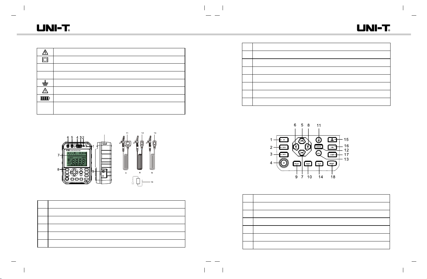
Red high-voltage test lead: 1 pc
Green test lead: 1 pc Black test lead: 1 pc
0℃~35℃; <75%rh
-20℃~60℃; <80%rh
<2000m
2
CAT Ⅳ 600V
IEC61010-1; EN IEC 61010-2-034;
BS EN 61010-1; BS EN IEC 61010-2-034
230mm(L)x161mm(W)x90mm(D)
About 1800g (including battery)
Dimensions
Weight
Test leads
Operating environment
Storage environment
Altitude
Pollution degree
CAT rating
Safety standards
Please check if any accessory in the package is missing or damaged:
1. User manual: 1 pc
2 Test lead (red, black, green: 1 for each): 3 pcs.
3 USB cable: 1 pc.
4 Lithium battery charger (model: CS36M168200M1; specification:
Input:100-240Vac (Fluctuations+10%), 50/60Hz, 0.8A,Output: 16.8Vdc, 2A:
.
1 pc (UT512E)
5 Lithium battery pack (installed inside the tester, model: UT-M18, .
specification: 14.8V, 5200mAh): 1 pc (UT512E)
6 Adapting charging stand (optional accessory, model: UT-W12, for UT512E only).
7 8 PCS LR14 alkaline batteries (UT512D).
8 Carrying strap:1pc.
If any missing or damaged accessory occurs, please contact with the supplier
immediately.
UT512D/E User ManualUT512D/E User Manual

11 12
IV. Electrical Symbols
CAT IV
DC
AC 11
12
13
14
7
1
2
3
4
5
6
7
8
9
10
1
2
3
4
5
6
10
Risk of electric shock
Double-insulated or insulation-enhanced
Direct Current
Alternating Current
Grounding
Warning
Battery voltage
It is applicable to test and measuring circuits connected at the
source of the building’s low-voltage MAINS installation
V. External Structure
Battery charging port
Selection switch for charging and testing modes
LINE: High-voltage output outlet (dual-plug red lead)
LINE: Outlet for shielding high-voltage lead (dual-plug red lead)
GUARD: Grounding protection outlet (single-plug green lead)
EARTH: High resistance measurement outlet (single-plug black lead)
LCD segmented display screen
Functional buttons
USB port
Carrying strap location
Dual-plug high-voltage test lead (red)
High resistance sampling test lead (black)
Protective test lead (green)
Lithium battery charger
VI. Button Description
Insulation resistance measurement mode
Power on/off
Increase; select high range or previous group of data
Decrease; adjust time and resistance; cyclically display
Decrease, select low range or next group of data
Fig. 5.1 External structure
Fig. 6.1 UT512D Functional buttons
UT512D/E User ManualUT512D/E User Manual
DC voltage measurement mode
AC voltage measurement mode

13 14
8
9
10
11
12
13
14
15
16
17
18
Compare resistance test
Conduct testing
Increase; adjust time and resistance; cyclically display
Read data
Save data
Backlight
Confirm parameter setting
Return
Delete saved data
Upload data
Timer resistance test
8
1
9
2
3
4
5
6
7
10
11
12
13
14
15
16
18
17
/R
1
2
3
4
5
Battery power
Battery charging
Live measured object or risk of high voltage
Failed resistance comparison testing
Bluetooth
Insulation resistance measurement mode
AC/DC voltage measurement mode
Power on/off
Increase; select high range or previous group of data
Decrease; adjust time and resistance; cyclically display
Decrease, select low range or next group of data
Increase; adjust time and resistance; cyclically display
Read data
Save data
Backlight
Confirm parameter setting
Return
Delete saved data
Upload data
Timer
Compare resistance
Conduct testing
/ R capacitance/Resistance measurement mode
Figure 6.2 UT512E functional buttons
VII. LCD Display
UT512D/E User ManualUT512D/E User Manual
Figure 7.1 Symbols on LCD

15 16
8
9
6
7
10
11
19
12
20
13
14
15
16
17
18
21
22
23
31
24
25
26
27
28
29
30
Pass resistance comparison testing
USB communication
Buzzer
Analog bar graph of insulation resistance testing
Data hold
Indication of dangerous operation
Monitoring display of voltage output
Polarization index testing mode
Dielectric constant testing mode
DC voltage testing mode
AC voltage testing mode
Dielectric absorption ratio testing mode
Inverted input of DC voltage testing
Over-range test result
Comparison resistance setting or timer setting
Display area of measured insulation resistance,
AC/DC voltage, capacitance, etc.
Timer
Stepping indication
Resistance comparison mode
Time1 of the timer
Time2 of the timer
Save data
Read data
Data storage capacity
Wi-Fi communication
Leakage current display
VIII. Button Operation
Power button
Long press this button for 2 seconds to turn on the tester (full symbols are displayed
on LCD for 1 second), long press again to turn it off. The tester is designed with
auto power off function.
IR
Insulation resistance testing button: The default mode is continuous insulation
resistance testing mode when powering on the tester. Short press this button to
switch to insulation resistance testing function.
● V (UT512E)
AC/DC voltage testing button: Without high voltage output, short press “V” button
to switch to AC/DC voltage testing mode. The tester can identify AC/DC voltage
automatically.
● DCV (UT512D)
DC voltage testing button: Without high voltage output, short press “DCV” button
to switch to DC voltage testing mode. DC voltage can be tested only.
● ACV (UT512D)
AC voltage testing button: Without high voltage output, short press “ACV” button
to switch to AC voltage testing mode. AC voltage can be tested only.
● /R (UT512E)
Capacitance/Resistance testing button: Without high voltage output, short press
“ /R” to switch to capacitance testing mode, short press again to switch to
resistance testing mode.
● ▲
A. Under insulation resistance measurement or capacitance measurement condition
and without testing voltage output, short press ▲ to select high-range voltage
output.
B. For data reading, press ▲ to select last group of data.
C. For time or resistance setting, press ▲ to increase time or resistance.
● ▼
A. Under insulation resistance measurement or capacitance measurement condition
and without testing voltage output, short press ▼ to select low-range voltage
output.
B. For data reading, press ▼ to select next group of data.
C. For time or resistance setting, press ▼ to decrease time or resistance.
UT512D/E User ManualUT512D/E User Manual

17 18
A. Under insulation resistance measurement condition and without testing voltage
output, press to progressively decrease at the step of corresponding range
(decrease by 50% at a step of 10% each).
B. When setting time or resistance, button is used as a cursor button to adjust
time and resistance.
C. After polarization index or absorption ratio measurement is completed, press
to cyclically display polarization index or absorption ratio, insulation resistance in
Time2 and Time1.
A. Under insulation resistance measurement condition and without testing voltage
output, press to progressively increase at the step of corresponding range
(increase by 120% at a step of 10% each).
B. For time or resistance setting, button is used as a cursor button to adjust time
and resistance.
C. After polarization index or absorption ratio measurement is completed, press
to cyclically display polarization index or absorption ratio, insulation resistance in
Time2 and Time1.
READ
Without high voltage output, short press “READ” to read latest group of saved data,
and press ▲ and ▼ to select different data.
SAVE
Short press “SAVE” to save current displayed data. The LCD shows the symbol “FUL”
and the number of group “999” to indicate full storage. To save next group of data,
please clear the saved data.
Backlight button
Short press this button to turn on/off the backlight.
Setting confirmation button
For setting parameter in non-testing state, short press “ENTER” to confirm the setting
and exit the current setting.
Setting cancellation/exit button
For setting parameter without high voltage output, short press “ESC” to cancel current
setting and exit. Under “TIME” and “COMP” modes, short press “ESC” consecutively
for twice to return to the interface of continuous insulation resistance measurement.
Data deletion button
In “READ” state, short press “CLR” and then press “ENTER” to delete current data,
press “ESC” to exit data deletion function. In “READ” state, the symbol “CLR” and
the storage capacity symbol “2Hz” flash when “CLR” is long pressed for 2 to 3
seconds, press “ENTER” to confirm clearing all saved data, press “ESC” to exit data
deletion function. Note: To delete all saved data after short pressing “CLR”, please
long press “CLR” directly to enter after pressing exit button.
Data upload button
Short press this button to select USB data transfer mode, current transfer mode
can be displayed on the LCD synchronously , select current mode to transfer data
through confirmation button.
When connected to the computer software, press and hold this button to upload all
stored data to the PC.
USB: Active uploading for the tester.
Timer setting button
The default mode of the tester is continuous insulation resistance measurement
mode. Under insulation resistance measurement condition and without testing voltage
output, perform time setting for insulation resistance measurement mode.
Short press “TIME” to cyclically select “Continuous Measurement”, “Timer
Measurement”, “Polarization Index Measurement” and “Absorption Ratio
Measurement”, press “ENTER” to confirm the selection, press “ESC” to unselect
and return to default measurement mode.
Comparison measurement button
Under insulation resistance measurement condition and without testing voltage
output, short press “COMP” to select resistance comparison measurement as
insulation resistance measurement mode, the default comparison value is 10MΩ.
Measurement button
This button is used to turn on/off insulation resistance measurement or capacitance
measurement. Long press “TEST” for more than 2 seconds to start measurement.
If current measurement function is enabled, the red warning light illuminates the
background of “TEST” button. Short press “TEST” to exit measurement.
UT512D/E User ManualUT512D/E User Manual

19 20
IX. Testing Instructions
9.1 Testing Preparation
(1) Press the power button for more than 2 seconds to turn on the tester. The tester
enters default state after full symbols are displayed on LCD for about 1 second.
Fig. 9.1.1 Full symbols shown on LCD
(2) When the battery power indicator shows only one “segment” of power left, the
indicator flashes to indicate that the battery power is almost used up, which means
battery charging or replacement is needed. If the battery power indicator shows
no “segment”, it means the batter power cannot meet power demand, the tester
must be charged or the battery must be replaced. The relation between “segment”
left and “battery voltage” is shown in the table below:
Battery power
symbol indicator
No segment
1 segment
2 segments
3 segments
4 segments
Battery voltage (UT512E)
≤13.5V (Power off after
“2Hz” flashes 10 seconds)
13.6~14.3V (“1Hz” flashes)
14.4~15.1V
15.2~16.0V
>16V
Battery voltage (UT512D)
≤9.0V (Power off after
“2Hz” flashes 10 seconds)
9.1~10.4V (“1Hz” flashes)
10.5~11.9V
11.0~12.2V
>12.2V
Note: Do not perform measurement during charging for UT512E, as interlock is
designed between testing and charging ports in structure. UT512D cannot be charged,
if low battery occurs, please replace with battery in same type.
9.2 Battery Charging (UT512E)
When charging with battery charger in power on state, the battery power indicator
and the charging symbol are displayed (not displayed when charging in power off
state). When charging with the charging stand, the charging symbol lights up (lighting
up red for “under charging”; green for fully charged; flashes in red and green alternately
to indicate threshold state).
Note: The red indicator light at the battery charger only indicates energizing when
connecting with power grid, it does not indicate if the battery is fully charged. Please
observe the battery charging symbol on the LCD when powering on the tester, to
judge if the battery is charged fully.
To prevent high-voltage electric shock caused by mistaken testing during
charging, the tester is designed with poka-yoke mechanism to meet the safety
standards, that is, the tester cannot be charged with the charger during test, and
the test lead cannot be connected during charging.
UT512E is built with rechargeable lithium battery pack (14.8V, 5200mAh). Please
charge with the supplied dedicated lithium battery charger (16.8V, 2A) (Figure 9.2.1),
or remove the lithium battery pack and then charge it with the adapting charging
stand (optional), as shown in figure 9.2.2.
Fig. 9.2.1 Tester charging
UT512D/E User ManualUT512D/E User Manual

21 22
9.3.1.1 Continuous Insulation Resistance Measurement
When the tester is powered on, it enters the default mode of continuous insulation
resistance measurement (250V output voltage). Connect test leads with measured
object, press ▲ and ▼ to select high-voltage range, press and to select fine-
tuned step voltage, then press “TEST” to perform test, the LCD shows basic elements
including battery power, high-voltage warning symbol (“2Hz” flashes), leakage current,
real-time output voltage, measured insulation resistance, testing value of analog bar
graph, continuous measurement duration, storage capacity, etc. Press “TEST” to
end the testing, turn off the testing voltage of insulation resistance, turn off the testing
indicator light, and automatically discharge fast (discharge course is displayed), the
LCD maintains current measured element on it.
9.3.1.2 Timer Measurement
Under insulation resistance testing condition without high voltage output, press “TIME”
to enter timer measurement mode.
When cycling through in insulation resistance measurement mode, the display of
timer measurement mode differs from that of other measurement modes.
There is no time setting interface in the default continuous mode interface, there is
PI symbol for polarization index measurement, and there is DAR symbol for absorption
ratio measurement.
When entering timer measurement mode, Time1 and timer symbol are displayed on
LCD, the default countdown of 05:00 flashes (mantissa) to indicate user can set the
time. Press and to select the digit (similar with cursor) of the time to be changed,
press ▲ and ▼ to change the value of the selected digit of the time, then press “ENTER”
to confirm and save the change or press “ESC” to cancel the change.
Press “TEST” to perform test, the LCD shows basic elements including battery power,
high-voltage warning symbol, leakage current, real-time output voltage, measured
insulation resistance, testing value of analog bar graph, Time1, set countdown time,
storage capacity, etc.
When the set time is up, the test ends automatically, the testing indicator light turns
off, and the tester automatically discharge fast (discharge course is displayed), the
LCD maintains current measured element on it.
Note: Before removing the lithium battery pack, please power off the tester and
remove all test leads to prevent electric shock!
9.3 Basic Measurement Operations
9.3.1 Insulation Resistance Measurement
Note:
To perform wiring and measurement operations, please wear high-voltage
insulation gloves and protective gear before testing.
Before testing, please make sure that the measured object is de-energized,
and do not measure the insulation of live equipment or circuit.
Please operate the tester with care as high-voltage output exists. Please
ensure good contact between measured object and test lead. Keep your hands
away from the test clips before pressing “TEST” button to perform test.
Do not short-circuit the two test leads during testing (high-voltage output state)
or measure insulation resistance after high-voltage output, otherwise it may
cause personal injury, fire or product damage.
Where R is the measured insulation, U is the tester output voltage and I is the
current of measured circuit.
R= U
I
Calculation formula: (Ohm’s law)
Fig. 9.2.2 Charged with charging stand (optional: UT-W12)
UT512D/E User ManualUT512D/E User Manual
For resistance below 1MΩ at the 250V range, the measurement duration cannot
exceed 10 seconds and multiple consecutive measurements cannot be performed.
For resistance below 2MΩ at the 500V range, below 5MΩ at the 1000V range,
and below 10MΩ at the 2500V range , the same limitations apply.

23 24
9.3.1.3 Polarization Index Measurement
Polarization Index (PI) refers to the value of measured resistance in 10 minutes to
that in 1 minute. It takes 10 minutes to perform polarization index testing. If the time
of insulation testing is 10 minutes or more, polarization index testing is completed
and saved.
PI=
R10min
R1min
>4 4~2 2~1 <1.0
Polarization Index (PI)
Insulation condition Very good Good Poor Dangerous
Press “TIME” button under insulation resistance testing condition without high voltage
output. When the LCD shows PI, it indicates the tester enters polarization index
measurement mode.
Then, the LCD shows PI, Time1, Time2, timer symbol, etc. In initial interface, the
default time of Times is 1 minute, that is 01:00 (the mantissa flashes to indicate
user can set the parameter). The default time of Time2 is 10 minutes, that is 10:00.
After completing setting Time1, the tester by default switches to setting state of
Time2. Press “ENTER” to confirm and save the change, or press “ESC” to cancel
the change.
Press “TEST” to perform test, the LCD shows basic elements including battery power,
high-voltage warning symbol, leakage current, real-time output voltage, measured
insulation resistance (Time1 or Time2), testing value of analog bar graph, Time1 or
Time2, set countdown time, PI, storage capacity, etc.
When the set time is up, the test ends automatically, the testing indicator light turns
off, the tester discharges fast, and the LCD shows the testing value. Press and
to cyclically display PI, insulation resistance in Time2, and insulation resistance
in Time1.
9.3.1.4 Dielectric Absorption Ratio Measurement
Dielectric Absorption Ratio (DAR) refers to the value of insulation resistance in
1 minute to that in 15 seconds. It takes 1 minute to perform absorption ratio testing.
The measurement data of all insulation testing in less than 1 minute are deemed
invalid. If the time of insulation testing is 1 minute or more, the absorption ratio
testing is included in the result.
DAR=
R1min
R15s
>1.4 1.25~1.0 <1.0
Dielectric Absorption Ratio (DAR)
Insulation condition Very good Good Dangerous
Press “TIME” button under insulation resistance testing condition without high
voltage output. When the LCD shows DAR, it indicates the tester absorption ratio
measurement mode.
Then, the LCD shows DAR, Time1, Time2, timer symbol, etc. In initial interface,
the default time of Time1 is 15 seconds that is 00:15 (the mantissa flashes to
indicate user can set the parameter). The default time of Time2 is 1 minute that
is 01:00. After completing setting Time1, the tester by default switches to the
setting state of Time2. Press “ENTER” to confirm and save the change, or press
“ESC” to cancel the change.
Press “TEST” to perform test, the LCD shows basic elements including battery
power, high-voltage warning symbol, leakage current, real-time output voltage,
measured insulation resistance (Time1 or Time2), testing value of analog bar
graph, Time1 or Time2, set countdown time, DAR, storage capacity, etc.
When the set time is up, the test ends automatically, the testing indicator light
turns off, the tester discharges fast, and the LCD shows the testing value.
Press and to cyclically display DAR, insulation resistance in Time2, and
insulation resistance in Time1.
UT512D/E User ManualUT512D/E User Manual

25 26
Note:
Do not measure AC power supply over 750Vac or DC power supply over
1000Vdc. It is possible to display higher voltage (10%), but it may damage the
tester.
Avoid electric shock when working with high voltage.
After completing all measurement operations, please disconnect the test
lead with the measured circuit, and remove the test lead from the input
terminal.
Black Red
Capacitor
9.3.1.5 Comparison Measurement
Press “COMP” button under insulation resistance testing condition without high
voltage output. When the LCD shows “COMP”, it indicates the tester enters
comparison measurement mode. The default comparison resistance is 10MΩ,
the initial interface flashes at the unit of 10MΩ at a frequency of 1HZ, to indicate
the tester is in comparison resistance setting state. Press and to select
the digit and unit of comparison resistance to be changed, press and to
adjust comparison resistance and unit, then press “ENTER” to save the parameter
setting or press “ESC” to cancel the parameter setting. After that, hold down
“TEST” for 2 seconds, if insulation resistance is less than comparison resistance,
the symbol “FAIL” will appear on the LCD, otherwise “PASS” appears.
To return to the continuous measurement interface, please press “COMP” in
“COMP” mode or press “ESC” twice consecutively.
9.3.2 Voltage Measurement
1) Connect red test lead with “LINE” input terminal, and black with “EARTH”.
2) Connect red and black alligator clips with measured circuit. For DC voltage
measurement, if the voltage of red test lead is negative, the negative symbol
“-” appears on the LCD.
Fig. 9.3.2.1 Wire connection of voltage measurement
Black Red
As a part of insulation measurement, the tester has circuit capacitance measurement
function. When CAP/R button is pressed without high voltage output, the tester
enters capacitance measurement function by default, with output voltage at 250V
range. Under capacitance measurement function, there are only three voltage
ranges including 250V, 500V and 1000V, which can be switched by pressing ▲
and ▼. For capacitance measurement, the tester calculates the capacitance by
measuring the charge and voltage of measured circuit under charge.
9.3.3 Capacitance Measurement (UT512E)
Fig. 9.3.3.1 Wire connection of capacitance measurement
UT512D/E User ManualUT512D/E User Manual

27 28
Calculation formula: C=
Q
U
Where C is measured capacitance, Q is the accumulated charge in the measured
object and U is the voltage of both ends of measured object.
Note: If the withstand voltage of the capacitor is less than the output voltage of
the capacitor, please do not perform measurement to avoid capacitor damage.
When measuring capacitor with polarity, please note that red test lead is the
negative of power output and black is positive, to avoid breaking down the
capacitor with polarity.
9.3.4 Low Resistance Measurement (UT512E)
Note: Be sure the circuit to be measured is de-energized before test. Do not
measure live equipment or circuit.
As a part of insulation testing, the tester has small resistance measurement
function (0.1Ω~600Ω). Without high-voltage output, press capacitance/resistance
button to enter capacitance measurement by default, press again to switch to
resistance measurement mode. “>660Ω” is displayed, as shown in figure 9.3.4.1.
(With external voltage input, the danger symbol flashes, in such case, do not
press the test button to measure resistance, as shown in figure 9.3.4.2). Under
resistance measurement function, connect the black grounding lead with EARTH
terminal, connect the green shielded lead with GUARD terminal, and disconnect
the red high-voltage lead; connect the green and black alligator clips with the
circuit to be measured; press the test button, then wait for the measurement
result. As shown in figure 9.3.4.3, the continuity of the grounding resistor is
measured.
X. Wire Connection Modes
10.1 . Cable Insulation Resistance Testing
There is leakage current at the surface of inner insulation layer near the end of
cable, the leakage current is included in the measured current of “-” terminal,
causing the measured resistance to be lower than actual insulation resistance.
This mode can be used for non-ultrahigh resistance measurement, as shown in
the figure below:
Fig. 10.1.1 Two-wire connection
Black Red
Shield
A. Two-wire connection
UT512D/E User ManualUT512D/E User Manual
Figure 9.3.4.1 Figure 9.3.4.2
Figure 9.3.4.3 Wire connection of low resistance measurement
Do not measure
in live state!
Black
Green

29 30
Wind the well-conducted bare wire around the exterior of inner insulation layer,
connect the safety terminal with the exterior conductor of inner insulation layer
in order to prevent current leakage at the surface of measured object. Surface
leakage current is conducted to the safety terminal, so as to eliminate the surface
leakage current at the measurement path between “+” and “-” poles, thus improving
the measurement accuracy, as shown in the figure below:
C. Ultra-high insulation resistance measurement with three-wire connection
Wind the well-conducted bare wire around the exterior of inner insulation layer,
connect the safety terminal with the exterior conductor of inner insulation layer
and the unused cable. Surface leakage current is conducted to the safety
terminal, so as to eliminate the surface leakage current at the measurement
path between “+” and “-” poles, thus ensuring the measured insulation
resistance is the insulation resistance between the selected cable and exterior
insulator, and eliminating the leakage path between cables, as shown in the
figure below:
Fig. 10.1.2 Three-wire connection
Black Red
Green
Shield
B. High resistance measurement with three-wire connection
Fig. 10.1.3 Three-wire connection
10.2 . Transformer Insulation Resistance Testing
A. Testing of insulation resistance between primary winding and grounding of
secondary winding
Fig. 10.2.1 Connection of testing
Black Red
Green
Shield
Black Red
UT512D/E User ManualUT512D/E User Manual

31 32
B. Testing of insulation resistance between grounding of primary winding and
secondary winding
Fig. 10.2.2 Connection of testing
C. Testing of insulation resistance between secondary windings
Fig. 10.2.3 Connection of testing
Black
Black
Red
Red
XI. Maintenance
Clean the casing:
1. Wipe the surface using soft cloth or sponge dipped with water
2. Do not immerse the tester in water to avoid tester damage.
3. Do not store the tester if it is wet.
4. The calibration and maintenance must be performed by qualified professional
repair personnel or specified repair department.
The contents of the User Manual are subject to change without further notice.
UT512D/E User ManualUT512D/E User Manual
This manual suits for next models
1
Table of contents
Other Unit Test Equipment manuals

Unit
Unit UPO1000CS Series User manual

Unit
Unit UTG1000X Series Owner's manual

Unit
Unit UTD4000 Series User manual

Unit
Unit UPO2000CS Series User manual

Unit
Unit UPO3000E Series Owner's manual

Unit
Unit UTD2000M User manual

Unit
Unit UT5300X+ Series User manual

Unit
Unit UT311A User manual

Unit
Unit UT528 User manual

Unit
Unit UT5583 User manual

Unit
Unit UT890D User manual

Unit
Unit UT512 User manual

Unit
Unit UT590 Series User manual

Unit
Unit UPO1000X Series User manual

Unit
Unit UT521 User manual

Unit
Unit UT12A User manual

Unit
Unit UT501A User manual

Unit
Unit UT-P35 User manual

Unit
Unit UTD2000CEX-II Series User manual

Unit
Unit UTD1000 Series User manual