Harvard Bioscience BTX AgilePulse ID User manual
AgilePulse™ID
In Vivo
Gene Delivery System
USER’S MANUAL

1
RESEARCH ONLY
BTX Harvard Apparatus
84 October Hill Rd
Holliston, MA 01746, USA
phone 1-508-893-8999 • fax 1-800-429-5732 • www.btxonline.com
BTX Warranty
Harvard Apparatus warranties the AgilePulse™In Vivo Gene Delivery System for a period of two years from the date
of purchase. At its option, BTX - Harvard Apparatus will repair or replace the unit if it is found to be defective as to
workmanship or materials. This warranty does not extend to any instrumentation which has been (a) subjected to
misuse, neglect, accident or abuse, (b) repaired or altered by anyone other than BTX - HARVARD APPARATUS without
BTX - HARVARD APPARATUS’ express and prior approval, (c) used in violation of instructions furnished by
BTX - HARVARD APPARATUS. This warranty extends only to the original customer purchaser.
IN NO EVENT SHALL BTX - HARVARD APPARATUS BE LIABLE FOR INCIDENTAL OR CONSEQUENTIAL
DAMAGES. Some states do not allow exclusion or limitation of incidental or consequential damages so the above
limitation or exclusion may not apply to you. THERE ARE NO IMPLIED WARRANTIES OF MERCHANTABILITY, OR
FITNESS FOR A PARTICULAR USE, OR OF ANY OTHER NATURE. Some states do not allow this limitation on an
implied warranty, so the above limitation may not apply to you.
Without limiting the generality of the foregoing, BTX - HARVARD APPARATUS shall not be liable for any claims of
any kind whatsoever, as to the equipment delivered or for non-delivery of equipment, and whether or not based on
negligence.
Warranty is void if the AgilePulse™instrument is changed in any way from its original factory design or if repairs are
attempted without written authorization by BTX - HARVARD APPARATUS.
Warranty is void if parts, connections or electrodes not manufactured by BTX - HARVARD APPARATUS are used with
the AgilePulse instrument. If a defect arises within the warranty period, promptly contact BTX - Harvard Apparatus, 84
October Hill Road, Building 7, Holliston, Massachusetts, USA 01746-1388 using our toll free number 1-800-272-2775 (US
Only) or 508-893-8999
Materials Authorization) number has been issued by our customer service department. The customer is responsible
for shipping charges. Please allow a reasonable period of time for completion of repairs, replacement and return. If the
unit is replaced, the replacement unit is covered only for the remainder of the original warranty period dating from the
purchase of the original device.
This warranty gives you specific rights, and you may also have other rights, which vary from state to state.
AgilePulse™ID In Vivo Gene Delivery System

2
SUBJECT PAGE
1 Introduction 5
2 Items of Particular Interest 6
3 AgilePulse™ Tutorial 7
3.1 Application 7
3.2 DNA Delivery Methods 7
3.3 DNA Delivery into Cells Using Electroporation 8
3.3.1 General Electroporation Discussion 8-10
3.3.2 AgilePulse™ Electroporation 11-12
3.3.3 Specific References 13
4 AgilePulse™ System Components and Set-up 14
4.1 Introduction 14
4.2 The AgilePulse Waveform Generator 14
4.2.1 Front Panel 15
4.2.2 Back Panel 15
4.3 Intradermal Electrode Array (ID) 15
4.4 Setting up the System 16
4.4.1 Initial System Test 16
4.4.2 Touch Screen Cleaning 17
5 System Operation 18
5.1 Vaccine Delivery Mode 18
5.1.1 USB Key/Memory Stick 18
5.2 Intradermal Array (IDA) Electrode 18
5.2.1 Handle 18
5.2.2 Electrode Tip 19
5.3 Waveform Generator 19
5.3.1 User Identification Input 19-20
5.3.2 Identification Input 20
5.3.3 Delivery Screens Functions and Operations 21-22
5.3.4 Experiment Delivery Logs 23
5.3.4.1 Text Log 24
5.3.4.2 CVS Data 25
5.3.5 Delivery Completion Return Codes 26
5.3.6 Software Maintenance Mode 27
5.3.6.1 User Account Maintenance 27
5.3.6.2 Log Retrieval 28
5.3.6.3 Pulse Protocol 29
6 Customer Service 30
7 Appendix 31
A AgilePulse™Specifications 31-32
Declaration of Conformity 33
Table of Contents

3
LIST OF FIGURES PAGE
3-1 Electroporation 8
3-2 Transmembrane Voltage 9
3-3 Two Needles per Row Field 12
3-4 Electrical Field Coverage 12
3-5 Bleb Formation 12
4-1 Waveform Generator 14
4-2 AgilePulse Front Panel 15
4-3 Login Screen 16
4-4 System OK Screen 16
4-5 Self Check Not Successful Screen 16
5-1 IDA Electrode Handle 18
5-2 IDA Tip 19
5-3 Attaching IDA Tip to Handle 19
5-4 User Login Screen 19
5-5 Opening Screen 20
5-6 Delivery Screen - Initialization 21
5-7 Delivery Screen – Load Estimation 21
5-8 Delivery Screen – High Voltage Power Supply Charge 22
5-9 Delivery Screen – Pulse Waveform Active 22
5-10 Delivery Screen – Shutdown 22
5-11 Text Log Screen 24
5-12 Sample Amplitude Analysis 25
5-13 User Account Maintenance 27
5-14 Log Retrieval Screen 28
5-15 Pulse Protocol Modification 29
Table of Contents

4
This instrument contains a high voltage power supply adjustable to 1,000 volts. High voltage
power supplies present a serious risk of personal injury if not used in accordance with design
and/or use specifications, if used in applications on products for which they are not intended or
designed, or if they are used by untrained or unqualified personnel.
• The user must read this manual carefully before the instrument is placed into operation.
• Removing the cover may void the warranty.
• Do not connect or disconnect the high voltage cable with the high voltage enabled.
To connect or disconnect the cable, turn line power off and unplug line (mains) cord.
• Do not touch the electrode tip while the waveforms are being applied
• If a problem occurs during a run, push the STOP/RESET button on the front panel.
If there are any questions about the operation of this instrument, call BTX Customer service at
1-508-893-8999.
Caution Notice

5
This product should not be used in the presence of a flammable atmosphere such as an anesthetic mixture
with air, oxygen, or nitrous oxide.
Caution
For research only. Not for clinical use on patients.
Caution Risk of
Electric Shock
Operating
Instructions
Caution
The AgilePulse™IM system was developed to deliver small molecules using pulsed electric fields (electroporation).
The system has been designed for research purposes.
The system has three components: the AgilePulse Waveform Generator, the Intramuscular Array (IMA)
electrodes (4 & 6) parallel needle arrays and the User Manual. Using other components may damage the
system, will certainly provide degraded performance and invalidate the warranty.
NOTE: The AgilePulse Waveform Generator contains a high voltage power supply and was
designed with safety features to protect the user and the equipment. If used properly, the
AgilePulse Waveform Generator is a safe and reliable instrument.
Front and Back Panel Symbols
AC Mains
Introduction
1
Off FuseOn

6
The AgilePulse™ID DNA Vaccine Delivery System is a sophisticated system designed for delivery of
DNA vaccines to the skin. The following are important:
1. The system shall only be used as described in this User Manual,
the user is required to read the User Manual and undergo training before use.
2. Certain concepts and processes are covered by patents, patents pending,
know-how and trade secrets.
3. The IDA electrode tip is disposable, single use , and sterile unless otherwise
indicated on the wrapper label.
4. Do not, under any circumstances, turn the power switch off while the system
is pulsing; if an emergency occurs push the emergency button on the front panel.
5. Do not connect or disconnect any electrode from the waveform generator when
the pulse waveforms are being applied.
6. Do not put your fingers or any other object on the ID electrode tip while pulse
waveforms are being applied.
7. This system produces voltages as high as 1000 volts and may cause injury or
death if used improperly.
8. The system shall not be used in the presence of flammable anesthetic.
BTX welcomes any comments from the users to improve this manual.
Items of Particular Interest
2

7
System Name Company Mechanism Target Factors
(all pain ratings are estimates)
AgilePulse™BTX Inject vaccine in dermis
with hypodermic
needle, insert needle
array, apply electric
field to deliver into cells
Dermis • Large dose
• Reduced pain compared to
other electroporation systems
• Pain 3 out of 10
• High cell transfection
PMED™PowderMed Microscopic particles
coated with DNA,
delivered into cells
using compressed
helium
Epidermis • Small doses
• Possible tattooing
• Pain 3 out of 10
• Low/Medium cell transfection
Biojector®2000 Bioject Medical
Technologies
Inject using CO2
pressure with spacer
(subcutaneous) or w/o
spacer (to muscle)
Skin or Muscle • Large doses
• Pain 3 out of 10
• Medium cell transfection
Many (muscle
electroporation)
Many Inject into muscle insert
electrode and apply
electric field
Muscle • Large dose
• Significant pain
• Pain 5-6 out of 10
• High cell transfection
Many Many Deliver viral vector with
hypodermic needle into
muscle
Muscle • Immune system reacts to viral
vector, inefficient when
boosting
• Pain 2 out of 10
3.1 Applications
The AgilePulse™system is used to deliver DNA vaccines to study the effects and potential of this application for research
purposes only. The AgilePulse™system has been shown to increase DNA delivery to cells resulting in
100-1000 times higher protein expression compared to hypodermic needle injection alone (Roos et al., 2006).
The AgilePulse™system is typically used to deliver cancer vaccines in doses of 50 µg or more. The AgilePulse™system
includes a AgilePulse voltage waveform generator and an Intradermal Array (IDA) electrode used to convert the voltage
to electric fields which deliver the vaccine directly into cells in the skin.
3.2 DNA Vaccine Delivery Methods
There are several methods used to deliver DNA vaccines.
AgilePulse™Tutorial
3
8
Ions
Gene
Cell
Membrane
Before Field Applied
Field Applied-Ions Move
Field Applied-Pathways Form
Field Removed-Membrane Seals
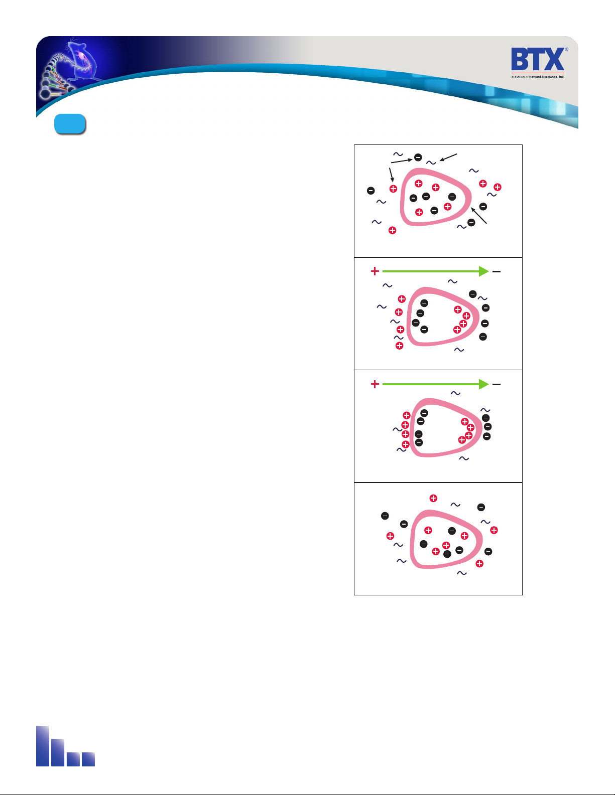
Figure 3-1: Electroporation
3.3 DNA Delivery Into Cells Using
Electroporation
3.3.1 General Electroporation Discussion
Electroporation is the use of a transmembrane electric field pulse to
induce microscopic pathways (pores) in a bio-membrane. Their presence
allows molecules, ions, and water to pass from one side of the membrane
to the other. As the right side bar shows, when the electric field is applied
the ions inside and outside the cell membrane migrate. As the charge
builds up on either side of the membrane the membrane weakens and
the pathways form permitting material outside of the cell to enter. If the
electric field is promptly removed the pathways close and the membrane
reseals. If the electric field duration is too long the pathways increase and
the cell is killed. Efficient electroporation depends on proper selection
of electric field waveforms. The electropores are located primarily on the
membrane areas which are closest to the electrodes. The pathways form
in about a microsecond and seal in seconds to minutes. The duration of
the electric field is tens of microseconds to tens of milliseconds.
The use of electroporation was described by Neumann in the early
1980. The routine use of electroporation became very popular with
researchers through the 1980s because it was found to be a practical
way to place drugs, or other molecules into cells. In the late 1980s,
scientists began to use electroporation for applications in multi-cellular
tissue.
In the early 1990’s Lluis Mir of the Institute Gustave-Roussy was the first
to use electroporation in a human trial to treat external tumors.
Research has shown that the induction of pathways is affected by three
major factors. First, cell-to-cell biological variability causes some cells to be
more sensitive to electroporation than other cells. Second, for pathways
to be induced, the product of the pulse amplitude and the pulse duration
has to be above a lower limit threshold. Third, the number of pathways
and effective pathway diameter increases with the product of “amplitude”
and “duration.” Although other factors are involved, this threshold is now
understood to be largely dependent on a fourth factor, the reciprocal
of cell size. If the upper limit threshold is reached pore diameter and
total pore area are too large for the cell to repair by any spontaneous or
biological process. The result is irreversible damage to the cell or cell lysis.
Because the mechanism of electroporation is not well understood, the
development of protocols for a particular application has usually been
achieved empirically, by adjusting pulse parameters (amplitude, duration,
number, and inter-pulse interval).
AgilePulse™Tutorial
3
9
3.3 DNA Delivery Into Cells Using Electroporation (cont’d)
3.3.1 General Electroporation Discussion (cont’d)
Research in the late 1980s and early 1990s showed that certain experimental conditions and parameters of
electrical pulses may be capable of causing many more molecules to move per unit time than simple diffusion.
There is also good evidence (Sukharev et al., 1992) that DNA movement is in the opposite direction of the arrow
in the sidebar.
An additional important consideration is when the voltage pulse is applied to the cells and medium that the
amount of current that flows is dependent on the conductivity of the material in which the cells are located.
Some material is quite conductive and severe heating will occur if the pulse duration is too long. Therefore long
duration fields will kill cells by destroying the membrane and heating.
The electric field in which the cells are located is produced by two system components. The first is the voltage
waveform generator and the second is the electrode which converts the voltage into the electric field.
Neumann, Sowers and Jordan, 1998, pages 68-73 provides the equation that relates the transmembrane voltage
(TMV) to electric field intensity. As the charge accumulates at the membrane, which is a capacitance, the voltage
across the membrane increases.
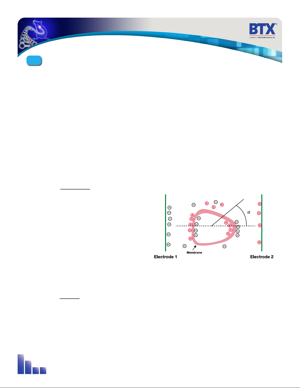
Figure 3-2: Transmembrane Voltage
voltage charge
capacitance
=
As the voltage increases from its quiescent value of a few tenths
of a volt to more than 0.5 volts, pathways begin to form. The
TMV is given by:
TMV 3⁄2
-
E r | cos a|
where:
E = electric field intensity in volts/cm
r = the cell radius in cm
a= angle off the center line
To produce a TMV of 1 volt across the membrane of a cell with 7
µm radius, the required electric field intensity is:
2⁄3
= = 950 volts / cm
1
7 *10-4
E
-
AgilePulse™Tutorial
3

10
General References:
Dimitrov, D.S., and Sowers, A.E., (1990) Membrane electroporation - fast molecular exchange by
electroosmosis. Biochimica et Biophysica Acta 1022: 381-392.
Sukharev SI, Klenchin VA, Serov SM, Chernomordik LV and Chizmadzhev YA, (1992) Electroporation, and
electrophoretic DNA transfer into cells: The effect of DNA interaction with electropores, 1992, Biophys J. 63:
1320-1327.
Nickoloff, Jac A., ed. (1995) Plant Cell Electroporation and Electrofusion Protocols, Methods in Molecular
Biology, Volume 55. (Humana Press, Totowa, New Jersey).
E. A. Disalvo and S.A. Simon, eds. (1995) Permeability and Stability of Lipid Bilayers (CRC Press, Boca Raton),
p 105-121.
Chang, D.C., Chassy, B.M., Saunders, J.A. and Sowers, A.E., eds. (1992) Guide to Electroporation
and Electrofusion, (Academic press, San Diego), 581 pp.
Neuman, E., Sowers, A.E., and Jordan, C.A.., eds. (1989) Electroporation and Electrofusion in
Cell Biology, (Plenum Press, New York) 581 pp.
Bartoletti, D. C., Harrison, G. I., & Weaver, J. C. (1989). The number of molecules taken up by
electroporated cells: quantitative determination. FEBS Lett., 256, 4-10.
Djuzenova, C. S., Zimmermann, U., Frank, H., Sukhorukov, V. L., Richter, E., & Fuhr, G. (1996). Effect of
medium conductivity and composition on the uptake of propidium iodide into electropermeabilized
myeloma cells. Biochim.Biophys.Acta, 1284, 143-152.
Klenchin VA, Sukharev SM, Chernomordik LV, Chizmadzhev YA, Electricaly induced DNA uptake by cells
is a fast process involving DNA electrophoresis, 1991, Biophys J. 60:804-811 Neumann, E., Kakorin, S.,
& Toensing, K. (1999). Fundamentals of electroporative delivery of drugs and genes. Bioelectrochem.
Bioenerg., 48, 3-16.
Neuman, E., Toensing, K., Kakorin, S., Budde, P., & Frey, J. (1998). Mechanism of electroporative dye
uptake by mouse B cells. Biophys.J., 74, 98-108. Sukharev, S. I., Klenchin, V. A., Serov, S. M., Chernomordik,
L. V., & Chizmadzhev, Y. (1992). Electroporation and electrophoretic DNA transfer into cells. The effect of
DNA interaction with electropores. Biophys.J., 63, 1320-1327.
Wolf, H., Rols, M. P., Boldt, E., Neumann, E., & Teissie, J. (1994). Control by pulse parameters of electric field-
mediated gene transfer in mammalian cells. Biophys.J., 66, 524-531.
Zerbib, D., Amalric, F., & Teissie, J. (1985). Electric field mediated transformation: isolation and
characterization of a TK+ subclone. Biochem.Biophys.Res.Commun., 129, 611-618.
AgilePulse™Tutorial
3

11
3.3 DNA Delivery Into Cells Using
Electroporation (cont’d)
3.3.2 AgilePulse™Electroporation
In section 3.3.1 general concepts of electroporation were
presented. This section presents the types of waveforms and
electrodes available for use in the AgilePulse™system.
Waveforms
Traditional in vivo electroporation uses four to six rectangular
pulses that are 100 microseconds in duration at a rate of one
per second. Thus the total treatment time is four to six seconds.
More advanced waveforms such as the PulseAgile®have been
found to be more effective in eliciting T-cell and antibody
responses simultaneously when delivering DNA vaccines (Roos
et al, 2006, Vertuani et al 2009, Bråve et al 2009). A PulseAgile®
waveform consists of various pulse groups with different
characteristics from group to group. For example, the study by
Dr. Roos found the optimum waveform for induction of high
gene expression and high induction of antigen-specific T cells to
be:
The total treatment time for this waveform is 0.27 seconds (this
waveform is currently tested in three clinical studies). When the
pulses are delivered in less than half a second there is only one
muscle contraction and tolerability is highly improved.
The AgilePulse™system has the following waveform settings
available:
Three groups may be used. A group is 1-10 pulses with the same
parameters. The system software automatically concatenates
each group.
Group Pulse
Amplitude
Pulse
Width
Pulse
Interval
Group
Interval
Pulse
Number
1 450 V
(1125 V/cm)
0.05 ms 300 ms 500 ms 2
2 110 V
(275 V/cm)
10 ms 300 ms 500 ms 8
Pulse
Amplitude
Pulse
Width
Pulse
Interval*
Maximum
Duty Cycle
Number
of Pulses
50 to
300 V
0.050 to
10 ms
0.2 to
1000 ms
50% 10
310 to 1000
V
0.050 to
1 ms
0.2 to
1000 ms
50% 10
Group Pulse
Amplitude
Pulse
Width
Pulse
Interval
Group
Interval
Pulse
Number
1 450 V
(1125 V/cm)
0.05 ms 0.2 ms 50 ms 2
2 110 V
(275 V/cm)
10 ms 20 ms 50 ms 8
*Limited to 50% Duty Cycle, i.e., (Pulse Width/Pulse Interval) less than or
equal to 0.5
The total treatment time for this waveform is 2.98 seconds.
(Waveforms for clinical use must be optimized in pre-clinical
studies.)
Another more recent study by Roos et al (Mol. Ther., 2009)
developed a variant of the PulseAgile®waveform described
above. This waveform is called Fast PulseAgile®(PAfast) and
differs only in the length of the pulse intervals:
AgilePulse™Tutorial
3
12
3.3 DNA Delivery Into Cells Using
Electroporation (cont’d)
3.3.2 AgilePulse™Electroporation (cont’d)
Electrode
Electrodes used in ex vivo and in vivo electroporation are quite
different. In ex vivo electroporation, the cells are generally placed
in an aqueous ionic medium in a chamber that has parallel plate
metal electrodes. This configuration produces very uniform
electric fields. For in vivo electroporation the electric fields must
be established in human tissue in the body. In this configuration
parallel plates are not practical for vaccine delivery.
For in vivo use two parallel rows of needles are used. This
configuration was first published in an abstract form by Dr. Julie
Gehl in 1997 (Herlev Hospital, Denmark).
Parallel row arrays must be carefully designed to produce
electric field intensities as close to uniform as possible to ensure
as many cells as possible are exposed to the same field. The key
parameters are:
• Number of needles in each row
• Diameter of the needles
• Spacing of the needles in the row
• Space between the two rows
In general the more needles per row and the greater the spacing
between the rows, the closer the electric field approaches that of
a parallel plate. As an example, the calculated electric field for two
needles per row is presented below:
As the spacing between the rows increases the electric field
rapidly falls off and cold spots form pores in the cells and vaccine
delivery does not occur.
The AgilePulse™needle electrodes are specifically designed to
produce near uniform electric fields in the treatment volume.
There are currently three ID electrodes available.
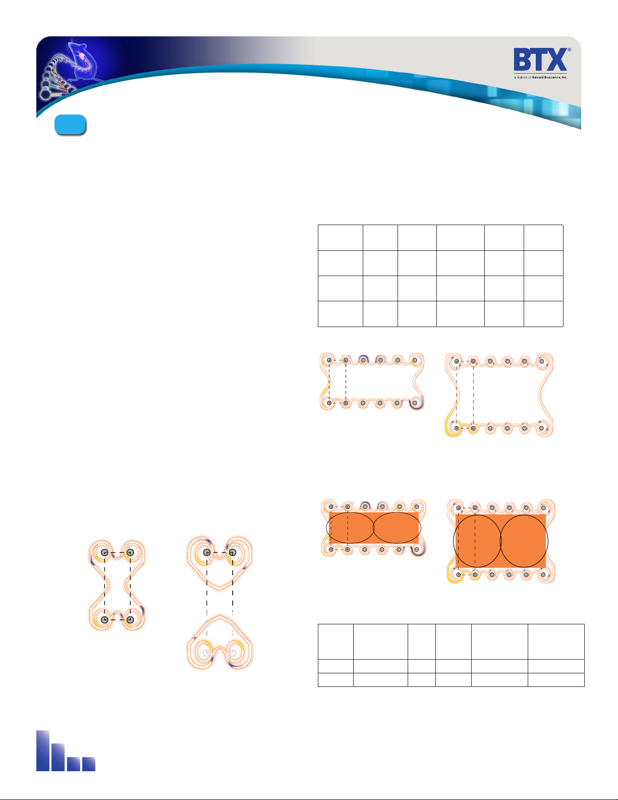
Figure 3-3 Two Needles per Row Field
ModelNo. Row
Space
Needle/
Row
Needle
Diameter
Needle
Length
Use
47-0040 4 mm 4 0.3 mm 2 mm Animal
Only
47-0050 4 mm 6 0.3 mm 2 mm Animal
Only
47-0060 6 mm 6 0.3 mm 2 mm Animal
Only
The electric field coverage is presented in Figure 3-4.
Figure 3-4: IDA-4-6-2 and IDA-6-6-2 electric field coverage
The recommended bleb placement for the IDA-4-6-2 and
IDA-6-6-2 electrodes is shown in Figure 3-5.
The total bleb volume for each is approximately:
There is a significant tradeoff between wider row spacing and
larger delivery volume and pulse amplitude. As pulse amplitude
increases so does pain of the applied pulse voltage.
Figure 3-5: Bleb Formation ID-4-6-2 and ID-6-6-2
Model
No.
Area Depth Volume
(approx)
Pulse Voltage
V/d=
1000 V/cm
Pulse Voltage
V/d=
1500 V/cm
47-0050 8.7 mm2 x2 2 mm 50-90 µl 400 600
47-0060 15.6 mm2 x2 2 mm 100 µl 600 900
4 mm
6 mm
4 mm
6 mm
4 mm
6 mm
AgilePulse™Tutorial
3

13
3.3.3 Specific References
There are ten specific references for this technique:
Gehl, Julie, Thesis, Copenhagen, May 2002
Roos A-K, Moreno S, Leder C, Pavlenko M, King A, Pisa P. Enhancement of cellular immune response to a
prostate cancer DNA vaccine by intradermal electroporation. Molecular Therapy, 2006. 13; 320-327.
Biragyn A, Schiavo R, Olkhanud P, Sumitomo K, King A, McCain M, Indig FE, Almanzar G, Baatar D. Tumor-
associated embryonic antigen-expressing vaccines that target CCR6 elicit potent CD8+ T cell-mediated
protective and therapeutic antitumor immunity. J Immunol. 2007 Jul 15;179(2):1381-8.
Roos A-K, King A, Pisa P. DNA vaccination for prostate cancer. Electroporation protocols: Experimental and
Clinical Medicine. Editor S. Li © Humana Press Inc., Totowa, NJ. Methods Mol Biol. 2008;423:463-72.
Vertuani, S, Triulzi, C, Roos, A-K, Pisa, P, Charo, J, Lemonnier, F, Nishimura, M, Seliger, S, Kiessling,
R. HER-2/neu mediated down-regulation of MHC class I antigen processing prevents CTL-mediated tumor
recognition upon DNA vaccination in HLA-A2 transgenic mice. 2008. Cancer Immunol Immunother. 2009
May;58(5):653-64. Epub 2008 Sep 27.
Lundberg K, Roos A-K, Pavlenko M, Wehrum D, Pisa P. A modified epitope identified for generation and
monitoring of PSA-specific T cells in patients on early phases of PSA-based immunotherapeutic protocols.
Vaccine. 2009 Mar 4;27(10):1557-65.
Bråve A, Hallengärd D, Gudmundsdotter L, Stout R, Walters R, Wahren B, Hallermalm K. Late administration
of plasmid DNA by intradermal electroporation efficiently boosts DNA-primed T and B cell responses to
carcinoembryonic antigen. Vaccine. 2009 Jun 8;27(28):3692-6. Epub 2009 May 3.
Roos, A-K, Eriksson, F, Walters, D, Pisa, P, King, A. Optimization of skin electroporation in mice to increase
tolerability of DNA vaccine delivery to patients. Molecular Therapy, 2009 Sep;17(9):1637-42. Epub 2009 Jun
16.
Lladser A, Ljungberg K, Tufvesson H, Tazzari M, Roos A, Quest FG, Kiessling R. Intradermal electroporation
with a survivin DNA vaccine induces CTLs against a self-epitope, suppresses angiogenesis and confers long-
term protection against mouse melanoma. Cancer Immunol Immunother. 2009 Jun 14. [Epub ahead of print]
Roos A-K, Eriksson E, Timmons J, Gerhardt J, Nyman U, Gudmundsdotter L, Bråve A, Wahren B, Pisa P. Skin
Electroporation: Effects on Transgene Expression, DNA Persistence and Local Tissue Environment. PLoS ONE.
2009 Sept 30.
AgilePulse™Tutorial
3

14
4.1 Introduction
The AgilePulse™system provides the capability of delivering
DNA vaccines to the dermis. The system is designed for easy
set-up and operation.
Specifications are presented in Appendices A and B, Tabs 7 and 8.
The AgilePulse™system is composed of three subsystems:
• Touchscreen controlled AgilePulse Waveform Generator
• Intradermal Array (ID) parallel, needle electrodes
• User Manual
Optional equipment available includes:
• Foot Pedal (47-0420)
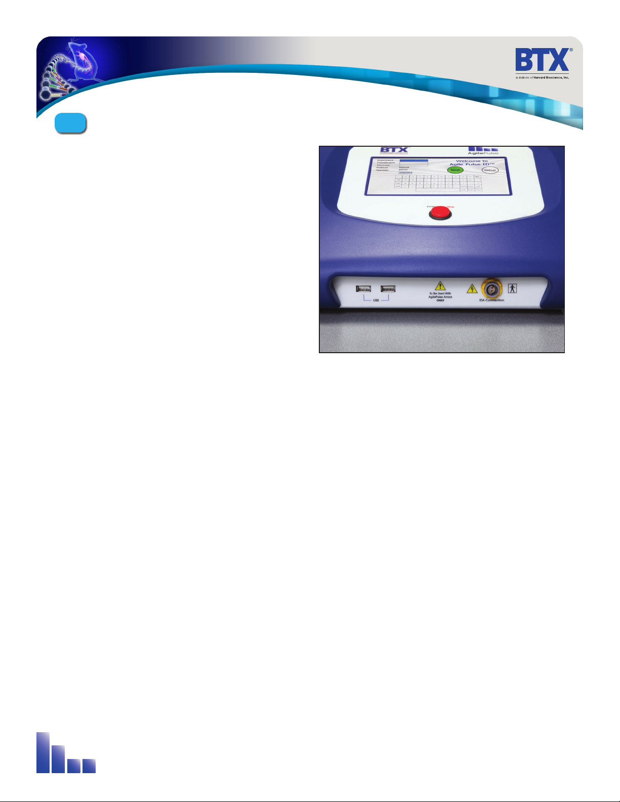
4.2TheAgilePulseWaveformGenerator
The Waveform Generator (Figure 4-1) is composed of a computer
and high voltage pulsing circuits. The computer runs mobile
Windows®and is operated by a touch screen. On the front panel
there is a power switch, a touch screen, an emergency stop
switch, an electrode connector and two USB ports. All User
inputs are entered via the touch screen. The system may be
operated by using an optional foot pedal. On the back panel
there is a line/mains power connector.
The high voltage pulsing circuits are controlled by a
microcontroller. The microcontroller accepts user inputs from
the touch screen and produces the pulse waveforms. A second
microcontroller is used as an independent audit of the waveforms
produced. If the audit function detects a deviation from the desired
pulse protocol, the system immediately terminates pulsing. The
system also digitizes the output of the pulse voltage and pulse
current monitors and calculates the skin resistance of the tissue
on each pulse. This is a significant quality control function that
indicates the vaccine is being delivered properly. After the vaccine
is delivered, a log of all parameters is saved in Internal Memory and
on a USB memory key, if one is inserted.
Figure 4-1: Waveform Generator
AgilePulse™System Components & Set-Up
4
15
4.2 The AgilePulse Waveform
Generator (cont’d)
4.2.1 Front Panel
The following can be found on the front panel: the Mains/Line
power switch (illuminated when on), the Emergency Stop button
switch, two USB ports, the ID Electrode Connector, and the User
Touch Screen (Figure 4-2).
One USB port can be used for a Memory Key. The data logs that
result from a vaccination are automatically stored on the Key if
one is inserted. The other USB port may be used for the optional
Foot Pedal (Appendix C, Tab 9).
The Emergency Stop button switch is used to stop system
operation. This switch immediately stops all pulsing and turns
off the high voltage power supply. The Line/Mains power switch
should never be used to turn off the system in an emergency
situation if pulsing is in progress.
4.2.2 Back Panel
On the back panel there is an IEC Power Entry module and
provisions for an Ethernet port.
Ethernet connectivity is not currently available.
4.3 Intradermal ARRAY Electrode (IDA)
The IDA consists of two parts: the handle and the tip. The handle
is connected to the waveform generator. The tip contains needle
electrodes used to deliver the DNA vaccine into the target cells.
The needle arrays are disposable, but can be used for multiple
experiments provided proper cleaning, and care of electrodes,
are followed, and sterilized.
Available needle configurations are described in Appendix A.
Figure 4-2: AgilePulse Front Panel
AgilePulse™System Components & Set-Up
4

16
4.4 Setting Up the System
The system will be set up in the following sequence:
1. Unpack the contents of the shipping box.
2. Check for obvious signs of exterior damage. If damage is
noted, contact BTX Customer Service before proceeding.
3. Place the Waveform Generator on the top of a sturdy table.
4. Connect the electrode cable into the connector at the
bottom right of the front panel.
5. Connect the mains/power cord into the back panel at the
bottom right.
6. Connect the foot switch (if applicable) into one of the USB
ports at the bottom left corner of the Waveform Generator
(front panel).
PLEASE CONTACT BTX IF YOU ARE INTERESTED IN AN ON
SITE TRAINING.
4.4.1 Initial System Test
This section will describe the process to verify mains/line cable
has been installed properly and the computer boots up.
1. Connect the system power cord to the mains.
(Plug in the device)
2. Turn the rocker switch (Line/Main Power) on the front
panel to the “on” position (I).
The rocker switch labeled “Power” should illuminate, and the
Login Screen should appear within 10 seconds. If the Waveform
Generator power switch fails to illuminate, then return it to the
OFF position (O). Verify the power cord is properly plugged into
the wall. Verify the wall socket is functional. If necessary, you
may need to check the fuse on the back panel of the Waveform
Generator. If it is faulty, replace it with the exact type fuse
(240V/5A, slo-blo) 5x20 mm.
If the power is properly applied, the screen should appear as that
shown in Figure 4-3. After entering the user login information and
tapping “OK”, the software continues its initialization procedure
and the NEXT button will have a white fill.
If the internal system checks are successfully completed, the
NEXT button will turn GREEN indicating the system is ready for
use (Figure 4-4). If the NEXT button turns RED, then the internal
checks failed (Figure 4-5). The system cannot be used if the
button is red. Contact BTX Customer Service for assistance.
Figure 4-3: Login Screen
(visible about 10 seconds after power on)
Figure 4-4: System OK Screen (Operating Correctly)
Figure 4-5: Self Check Was Not Successful Screen
AgilePulse™System Components & Set-Up
4

17
4.4 Setting Up the System (cont’d)
4.4.2 Touch Screen Cleaning
If the surface of the touch screen display needs to be cleaned, use a standard (non-ammonia) glass cleaner or mild detergent
with warm water and a soft, lint free paper or cloth towel. Do not apply the cleaning solution directly to the screen, to avoid
liquid running into other parts of the cabinet. Put a small amount of cleaner on the towel and gently rub the screen. Avoid
hard rubbing, abrasives, or harsh solvents like alcohol or ammonia.
AgilePulse™System Components & Set-Up
4

18
This chapter describes the procedure to operate the Waveform
Generator and to use the Intradermal Electrode.
5.1 Experiment Delivery
The user operates the system via the front panel touch screen.
When the power is turned on, the system boots up, and displays
the opening screen. The system is immediately ready for use. All
data logs produced for a vaccine delivery will be automatically
placed on a USB Key if one is inserted into an open slot on the
front panel. The user must ensure the USB Key is inserted before
the Protocol Delivery Screen is displayed, as the protocol pulsing
is started.
If the user does not have a USB Key inserted at run time, all run
history log files can be retrieved at a later time from the log files.
5.1.1 USB Key/Memory Stick
The USB key can be inserted into either of the two USB ports
that are located on the front panel of the waveform generator. It
should be inserted before delivering pulses and can be removed
at any time after the “saving data” message disappears. The
USB key may be removed without performing any additional
procedures. The data logs that result from a experiment are
automatically stored on the Key.
5.2 Intradermal Array (IDA) Electrode
The IDA Electrode consists of two parts: The Handle and the Tip.
5.2.1 IDA Electrode Handle
The Handle consists of an assembly into which the tip is placed
and a permanently attached cable. The cable is connected to the
Waveform Generator. The Handle is made of a durable plastic.
It is not sterile and may be cleaned with alcohol. The Handle is
reusable.
Figure 5-1: IDA Electrode Handle
System Operation
5
19
5.2 Intradermal Array (ID) Electrode
(cont’d)
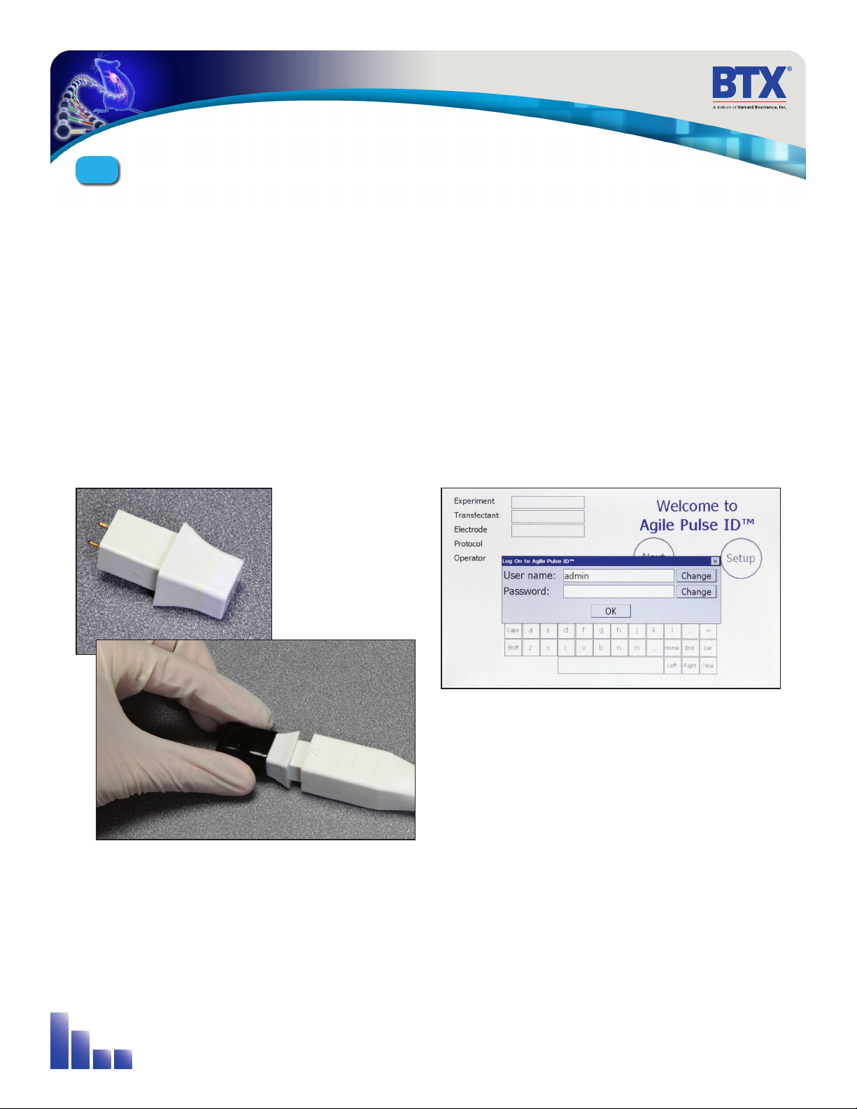
5.2.2 ID Electrode Tip
The IDA tip is recommended for and is single use, disposable.
The tip is made of medical grade plastic with surgical steel
needles. There are three tips that may be used with the Handle.
The tips are shipped in individual pouches. A cover is included to
protect the needles during shipping and handling.
When ready to use the electrodes, open the pouch and remove
the tip.
Insert the tip into the handle by aligning the arrow on the tip
with the arrow on the handle. Side grips have been added to the
tip for easier application.
Figure 5-2: IDA Tip
Figure 5-3: Attaching IDA Tip to Handle
Once the vaccine is ready for administration, remove the
protective cover from the IDA Tip taking care not to disconnect
the tip from the handle.
5.3 Waveform Generator
5.3.1 Login Screen – User Identification Input
After power is turned on, a Login Screen is presented
that requires the user to enter a user name and password
combination. The Login system is designed to prevent
unauthorized users from accessing the system and confine
authorized users to permissible activities.
Two types of users are defined: system administrator and
standard user. There is only one system administrator of the
system who has the ability to add/remove pulse waveform
protocols, add/remove standard user accounts, and assign pulse
waveform protocol access privileges to standard users. The
administrator always operates under the “admin” account.
Figure 5-4: User Login Screen
System Operation
5
Table of contents


