Hasco Z141/3 User manual
D / GB / F 04 / 22 Z 7
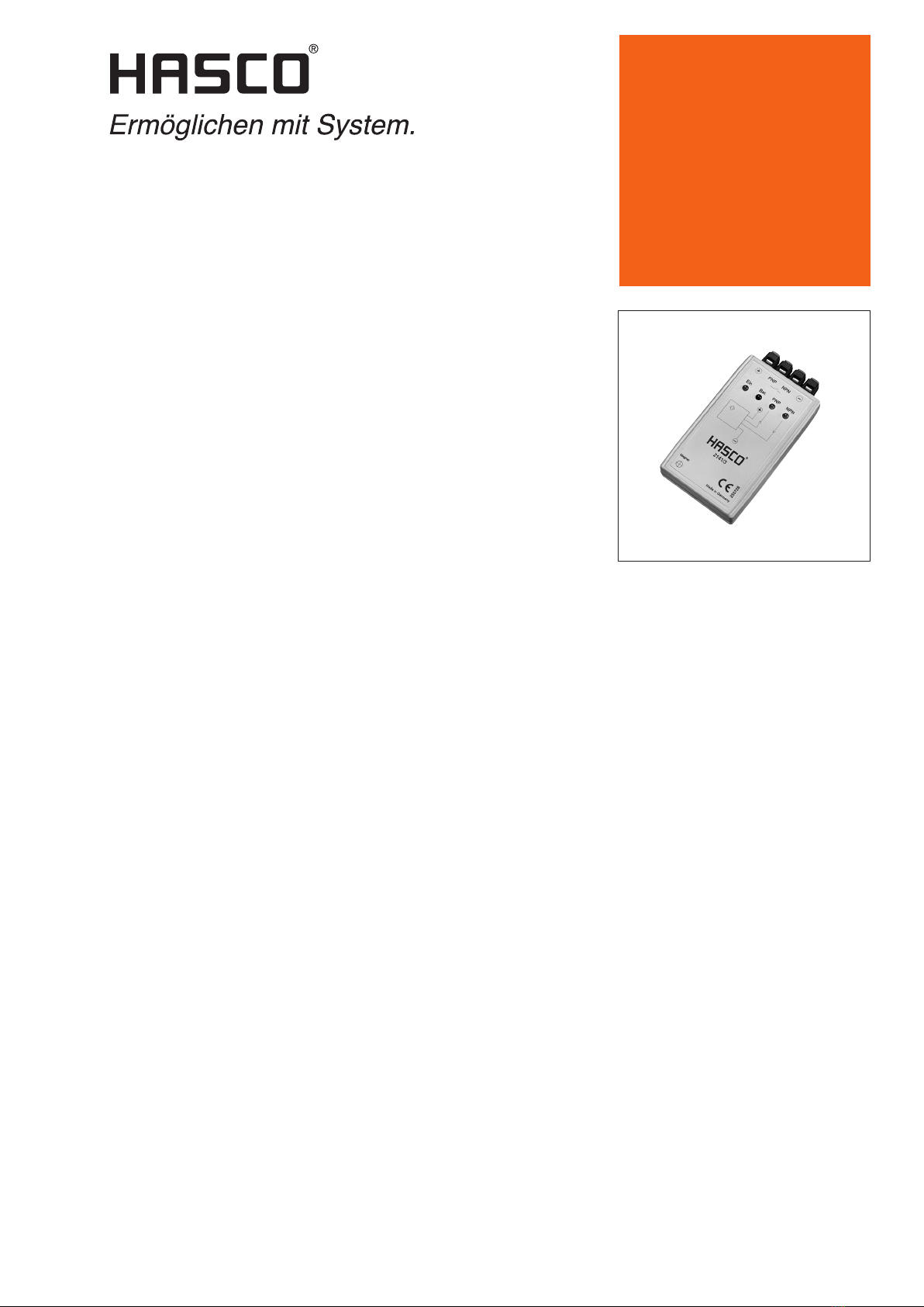
Prüfgerät
Tester
Contrôleur
Bedienungsanleitung
Operating instructions
Notice d’utilisation
Z141/3

2 HASCO
Z 141/ 3Bedienungsanleitung / Operating instructions / Notice d’utilisation
Prüfgerät für DC-Näherungsschalter
Prüft 2-, 3- oder 4-Draht DC-Nähe-
rungsschalter, ohne diese aus ihrer
Installation herauszunehmen.
1. Merkmale
1.1 Einheit mit vier Anschlüssen;
+UB, -UB, Eingang für PNP- und
NPN-Geräte.
1.2 Stromversorgung durch zwei
9V-Batterien. Wechsel durch
Öffnen des Gehäuses möglich.
1.3 LED-Anzeige
LED Funktionen Functions Fonctions
grün / green / verde I/O Sensor angeschlossen und
Einheit eingeschaltet
Sensor connected and unit
switched on
Capteur raccordé et
unité sous tension
rot / red / rouge Batterie
Unterspannungsanzeige
Battery
low voltage indication
Témoin
de sous-tension des piles
PNP / NPN Schaltzustandsanzeige Switching status display Témoin de l›état de
commutation
2. Prüfanweisung
2.1 Trennen Sie den Näherungs-
schalter von der Stromversorgung.
2.2 Schließen Sie den Näherungs-
schalter an den Z141/3 an.
Verdrahtung DC 3- oder 4-Draht
Näherungsschalter nach EU
Drahtfarbe
Wire colour
Couleur du l
Funktion
Function
Fonction
Verbinden mit
Connect to
Relier avec
braun /
brown / brun
positiv + +
schwarz /
black / noir
Ausgang normal geöffnet /
Outlet opened normally / Sortie normalement ouverte
PNP / NPN
weiß /
white / blanc
Ausgang normal geschlossen /
Outlet closed normally / Sortie normalement fermée
PNP / NPN
blau /
blue / bleu
negativ - -
Hinweis
Die Tabelle zeigt die europäische
Farbkodierung. Einige Schalter können
in der Farbkodierung variieren.
Falls Sie sich nicht sicher sind, folgen
Sie den Verdrahtungshinweisen des
Herstellers!
2-Draht DC-Schalter sind normaler-
weise braun/blau-kodiert.
Schließen Sie diese zwischen +UBund
Eingang PNP an. (PNP oder NPN ist
für 2-Draht-Schalter nicht relevant.)
Tester for DC proximity switches
Tests 2, 3 or 4-wire DC proximity
switches without the need to unins-
tall them.
1. Characteristics
1.1 Unit with four connections
+UB, -UB, input for PNP and
NPN devices
1.2 Power supply through two
9V batteries. Can be replaced
by opening the housing.
1.3 LED display
Contrôleur pour déclencheur
de proximité CC
Contrôle des déclencheurs de
proximité CC à 2, 3 ou 4 fils sans
les retirer de leur installation.
1. Caractéristiques
1.1 Unité à quatre connexions
+UB, -UB entrée pour appareils
PNP et NPN.
1.2 Alimentation électrique via deux
piles 9V. Remplacement possible
par ouverture du boîtier.
1.3 Afchage LED
2. Test instructions
2.1 Remove the proximity switch
from the power supply.
2.2 Connect the proximity switch
to the U141/3.
Wiring DC 3 or 4 wire
proximity switch to EU
2. . Instructions pour le contrôle
2.1 Débranchez le déclencheur de pro-
ximité de l’alimentation électrique.
2.2 Branchez le déclencheur de
proximité au Z141/3.
Câblage déclencheur de proximité
CC à 3 ou 4 fils conforme UE
Note
The table shows the European colour
coding. Some switches can vary in
the colour code.
If you are not sure, follow the
manufacturer’s wiring instructions!
2-wire DC switches are normally coded
brown/blue.
Connect them between +UBand input
PNP (PNP or NPN is not relevant for
2-wire switches).
Remarque
Le tableau indique le code couleur
européen. Certains déclencheurs
peuvent avoir un code couleur différent.
En cas d’incertitude, référez-vous aux
indications de câblage du fabricant!
Les déclencheurs CC à 2 fils ont
généralement un code brun/bleu.
Branchez les entre +UBet Entrée PNP.
(PNP ou NPN n’est pas pertinent pour
les déclencheurs à 2 fils.)

HASCO 3
Z 141/ 3Bedienungsanleitung / Operating instructions / Notice d’utilisation
2.3 Leuchtet die grüne LED, ist der
Näherungsschalter richtig
angeschlossen.
Leuchtet die rote LED, so zeigt
dies an, dass die Batterie-
spannung zu gering ist.
2.4 Richten Sie ein geeignetes Ziel-
objekt auf den Ansprechbereich
des Näherungsschalters aus.
Für einen induktiven Sensor muss
es sich um ein metallisches Ziel-
objekt handeln.
2.5 Bei korrekter Funktion des
Schalters, gibt der Z141/3 eine
akustische und visuelle
Rückmeldung.
Summer und LED eingeschaltet wenn
Buzzer and LED switched on when
Bipeur et LED activés si
Ausgangstyp des Näherungsschalters
Outlet type of the proximity switch
Type de sortie du déclencheur de proximité
PNP LED & Summer /
Buzzer / Bipeur
Zielobjekt vorhanden /
Target object available / Objet cible présent
Schließer no / PNP
Closer no / Contact travail no
PNP LED & Summer /
Buzzer / Bipeur
Zielobjekt nicht vorhanden /
Target object not available / Objet cible non présent
Öffner nc / PNP
Opener nc / Contact repos nc
NPN LED & Summer /
Buzzer / Bipeur
Zielobjekt vorhanden /
Target object available / Objet cible présent
Schließer no / NPN
Closer no / Contact travail no
NPN LED & Summer /
Buzzer / Bipeur
Zielobjekt nicht vorhanden /
Target object not available / Objet cible non présent
Öffner nc / NPN
Opener nc / Contact repos nc
2.3 If the green LED lights up,
the proximity switch is correctly
connected.
If the red LED lights up, it is an
indication that the battery charge
is too low.
2.4 Align a suitable target object
to the contact area of the
proximity switch.
For an inductive sensor, it must be
a metal target object.
2.5 When the switch functions
correctly, the Z141/3 will give
an acoustic and visual response.
2.3 Si la LED verte s’allume,
le déclencheur de proximité
est correctement branché.
Si la LED rouge s’allume,
cela indique que la tension des
piles est trop faible.
2.4 Amenez un objet cible approprié
dans la zone de détection du
déclencheur de proximité.
Pour un capteur inductif, il doit
s’agir d’un objet cible métallique.
2.5 Si le déclencheur fonctionne
correctement, le Z141/3 émet
une réponse acoustique et visuelle.
3. Sicherheitshinweise
3.1 Verbinden Sie das Prüfgerät nicht
direkt mit einer Stromleitung.
3.2 Tauschen Sie nicht die Batterie
aus, wenn das Prüfgerät
angeschlossen ist.
4. Austausch der zwei
9V PP3-Batterien
Stellen Sie sicher, dass das
Prüfgerät nicht angeschlossen
ist.
3. Safety instructions
3.1 Do not connect the tester directly
to a power line.
3.2 Do not replace the battery when
the tester is connected.
4. Replacing the two
9V PP3 batteries
Make sure that the tester
is not connected.
3. Consignes de sécurité
3.1 Ne raccordez pas le contrôleur
directement avec un câble
électrique.
3.2 Ne remplacez pas les piles lorsque
le contrôleur est branché
4. Remplacement des deux
piles 9V PP3
Assurez-vous que le contrôleur
n’est pas branché.
Das Produkt entspricht den
wesentlichen Schutzanforderungen
in Übereinstimmung mit den
EU-Richtinien.
The product complies with all
important safety instructions laid
down in the directives of the board
of European member countries.
Le produit satisfait aux principales
exigences de sécurité électrique
en accord avec les directives
européennes.

© by HASCO Hasenclever GmbH + Co KG · Postfach 1720 · D-58467 Lüdenscheid · Tel. +49 2351 957-0 · Fax +49 2351 957-237 · [email protected] · www.hasco.com 04 22 1 i
Technische Änderungen vorbehalten. Bitte überprüfen Sie stets sämtliche Angaben anhand unserer veröffentlichten Produktinformationen im Internet.
Subject to technical modications. Please always check all the data against the product information we publish in the internet.
Sous réserve de modications techniques. Veuillez toujours vérier toutes les données au moyen de nos informations produits publiées sur Internet.
Z 141/ 3Bedienungsanleitung / Operating instructions / Notice d’utilisation
Popular Test Equipment manuals by other brands


Kikusui
Kikusui TOS5200 user manual

Owon
Owon DSO-2072H quick start guide

BIRD
BIRD AT-400 Antenna Tester AT-400 Operator's manual

Ocean Optics
Ocean Optics XE-1 Xenon Installation and operation instructions

Hanna Instruments
Hanna Instruments HI 38077 instruction manual

Sourcetronic
Sourcetronic ST9010 Series user manual