Sourcetronic ST9010 Series User manual

SOURCETRONIC – Quality electronics for service, lab and production
AC/DC Hipot / IR Meter ST9010 series
User Manual

◇2
Content
Table of Contents
Chapter 1 Unpacking and Installing......................................................................................................................5
1.1 Precautions for Use............................................................................................................................................................5
1.2 Precautions when moving..................................................................................................................................................5
1.3 Connecting AC Power Cables...........................................................................................................................................6
1.4 Grounding..........................................................................................................................................................................6
1.5 Operation Check................................................................................................................................................................6
Checking Order................................................................................................................................................................................................................ 7
1.6 Other Characteristics .........................................................................................................................................................7
Chapter 2 Precautions on Handling.......................................................................................................................8
2.1 Prohibited Operation Behavior..........................................................................................................................................8
2.2 Actions When in Emergency.............................................................................................................................................8
2.3 Precautions in Testing........................................................................................................................................................9
2.4High Voltage TestWarning.................................................................................................................................................9
2.5 Handling for Dangerous State of Faulty Tester................................................................................................................10
2.6 Conditions for ensuring long-time trouble-free working.................................................................................................11
2.7 Daily inspection...............................................................................................................................................................11
Chapter 3 Panel Description.................................................................................................................................12
3.1 Front Panel ......................................................................................................................................................................12
3.1.1 USB Interface .........................................................................................................................................................12
3.1.2 Start Button.............................................................................................................................................................12
3.1.3 Stop Button.............................................................................................................................................................12
3.1.4 POWER..................................................................................................................................................................12
3.1.5 LCD Display...........................................................................................................................................................12
3.1.6 Shortcut Function Key............................................................................................................................................12
3.1.7 File Function Key...................................................................................................................................................13
3.1.8 Numeric keypad......................................................................................................................................................13
3.1.9 IndicatorArea..........................................................................................................................................................13
3.1.10 High voltage indication and Workinstruction ........................................................................................................13
3.1.12 Code switch and knob.............................................................................................................................................13
3.1.13 Testfunction area (FUNCTION) ............................................................................................................................13
3.1.14 Copy .......................................................................................................................................................................14
3.1.15 Instrument Model Label .........................................................................................................................................14
3.2 Rear Panel .......................................................................................................................................................................14
3.2.1 Product Name Plate.................................................................................................................................................14
3.2.2 Testunit output module...........................................................................................................................................14
3.2.4 High voltage output terminal (one per test unit).....................................................................................................15
3.2.5 Power socket: self-contained fuse box....................................................................................................................15
3.2.6 Protective ground terminal .....................................................................................................................................15
3.2.8 RS232C serial interface..........................................................................................................................................15
3.2.9 USB serial communication interface......................................................................................................................15

◇3
3.2.10 HANDLER interface ..............................................................................................................................................15
3.2.11 SINGLE interface...................................................................................................................................................15
3.3 Multi-unit scanner description.........................................................................................................................................15
3.3.1 UNIT n: Unit n........................................................................................................................................................16
3.3.2 CH n: scan channel n..............................................................................................................................................16
3.3.4 UNIT n INPUT/OUTPUT: Unit n input / output.....................................................................................................17
3.3.5 Power Input.............................................................................................................................................................17
3.4 Instrument Performance Overview..................................................................................................................................17
Figure 3-4 ST9010/A DC Voltage Output Range...................................................................................................................................................... 19
Chapter 4 Basic operation.....................................................................................................................................22
4.1Interface structure overview............................................................................................................................................22
4.2 Panel function interface and parameter description.........................................................................................................23
4.2.1 Test Interface...........................................................................................................................................................24
4.2.2 Setup Interface........................................................................................................................................................24
4.2.3 System Interface .....................................................................................................................................................25
1. SYSTEM related sub-interface.............................................................................................................................................................................. 26
3. Communication interface related sub-interface..................................................................................................................................................... 27
4. HANDLER communication interface setting............................................................................................................................................................. 28
4.2.4 FILE storage interface ............................................................................................................................................29
Note:30
4.3 Test project interface and parameter description.............................................................................................................30
4.3.1 AC withstanding voltage test parameter setting .....................................................................................................30
AC withstanding voltage (AC) test parameter description:............................................................................................................................................ 31
4.3.2 DC withstanding voltage test parameter setting .....................................................................................................31
DC withstand voltage (DC) test parameters are described below................................................................................................................................... 32
4.3.3 IR Insulation resistance test parameter setting........................................................................................................32
IR test parameters are as follows:................................................................................................................................................................................... 33
4.3.4 OS circuit test parameter setting.............................................................................................................................33
Open short circuit detection (OS) test parameters are as follows ................................................................................................................................... 34
4.3.5 S.CK Single-ended contact check parameter setting ..............................................................................................35
4.3.6 D.CK Double-ended contact check parameter setting ............................................................................................36
4.4 Test function principle and instructions for use...............................................................................................................36
4.4.1 Start Test..................................................................................................................................................................38
4.4.2 Test Delay...............................................................................................................................................................38
4.4.3 Voltage Rise............................................................................................................................................................38
4.4.4 DC boost decision...................................................................................................................................................38
4.4.5 High VoltageTest....................................................................................................................................................38
4.4.6 TestVoltage Fall......................................................................................................................................................38
4.4.7 Ground Current Detection Function.......................................................................................................................38
4.4.8 Current Overrun and Arc Detection (ARC)Function .............................................................................................39
4.4.9 Failure Judgment ....................................................................................................................................................40
4.4.10 TestResult Processing ............................................................................................................................................40
4.4.11 STOP (StopMeasuring)..........................................................................................................................................40
4.4.12 OFFSET (The base is cleared)................................................................................................................................40
4.5 SCAN multi-cell multi-channel scanning controller structure and use............................................................................41

◇4
4.5.1 After adding multiple scan channels, the instrument will add................................................................................41
4.5.2 Structural principle .................................................................................................................................................42
4.6 Structure and Use of HANDLER and SINGNAL Interface Circuit................................................................................42
4.6.1 Control Interface Theory..............................................................................................................................................42
4.6.2 HANDLER Control Interface Main Signal Timing Description ............................................................................43
4.7 File Storage Other interfaces and functions of the instrument.........................................................................................44
Chapter 5 Serial Port Commands Instruction....................................................................................................45
Brief Description of the Command Format:................................................................................................................................................................... 45
5.1 DISPlay Subsystem Commands......................................................................................................................................45
5.2 MMEM Subsystem Commands.......................................................................................................................................45
5.3 FUNCtion Subsystem Commands...................................................................................................................................46
5.3.1 FUNCtion test, Stop instruction..............................................................................................................................46
5.3.2 FUNCtion File Editing Function Commands .........................................................................................................46
5.3.3 FUNCtion Test Function, TestParameter Commands.............................................................................................46
5.3.4 Specific Examples of Command Data Format .......................................................................................................47
5.4 SYSTem Subsystem Commands.....................................................................................................................................54
5.5 Other Commands.............................................................................................................................................................56
Chapter 6 Appendix...............................................................................................................................................58

◇5
Chapter 1 Unpacking and Installing
This chapter tells some of the check points that must be performed after you receive the instrument
and things you must know before installing the instrument.
1.1 Precautions for Use
Be sure to follow the rules below when using the instrument:
Do not use the instrument in flammable air
To prevent burning or explosion, do not use the instrument near alcohol, thinner and other
flammable materials, or in air with high concentrations of these gases.
Avoid exposing the instrument to high temperatures and direct sunlight
Do not place the instrument where it is hot or where the temperature changes drastically.
Operating temperature range: 5℃to +35℃
Storage temperature range: -20℃to +60℃
Avoid wet environment
Do not place the instrument in a boiler, humidifier or high humidity environment with water.
Operating humidity range: 20% to 80%RH (dew condensation is not allowed)
Storage humidity range: <90%RH (dew condensation is not allowed)
Water condensation can cause the circuit to malfunction. The instrument can only be used when the
environment is completely dry.
Do not place the instrument in an environment with corrosive gas ordust
Do not use the instrument in an environment where corrosive gases such as sulfuric acid, fog, dirt
and dust or the like are present. This can corrode wires, connectors, and create hidden dangers or
connection defects that can cause malfunctions, failures, and even fires.
Do not use the instrument in a poorly ventilatedarea
The instrument has a forced air cooling system. Please allow enough space for the side and rear air
vents to ensure air circulation.
Do not use the instrument on a sloping surface or in a rockingplace
If the instrument is placed on a non-horizontal surface or shaken, the instrument may slip and
damage the instrument.
Do not use the instrument where there is a strong magnetic field or electric field effect
Use the instrument where there is a strong magnetic field or electric field. Electromagnetic pulses
can cause a malfunction in the instrument.
Do not use the instrument near sensitive measuring instrument orreceiver
Operation in a location subject, may cause such equipment be affected by noise generated by thetester.
At a test voltage exceeding 3 kV, corona discharge may be generated to produce substantial amounts
of RF broadband emissions between grips on the test lead wire. To minimize this effect, secure a
sufficient distance between alligator clips. In addition, keep the alligator clips and test lead wire away
from the surfaces of conductors (particularly sharp metal ends).
1.2 Precautions when moving
When moving or transporting the instrument, be aware of the following precautions:
Turnoff the power switch before moving
Moving with the power switch on will cause electric shock and damage.

◇6
Safe
ground
Disconnect all cables before moving
Moving the instrument without disconnecting the cable may result in damage to the cable or drop the
instrument during handling it.
1.3 Connecting AC Power Cables
The power cord is supplied by Sourcetronic along with the instrument. Do not use an AC power cord
that is not included with the instrument.
Connection order:
1. Make sure the power supply is within the power cord range of the instrument.
2. Determine the nominal value of the instrument fuse, the fuse box is installed in the correct
position (power supply)
3. Make sure the instrument's power switch is off
4. AC power cord is connected to the AC LINE (AC power cable) end of rearpanel.
5. Please use the supplied AC power cord, or the AC power cord selected by the qualified
professionals
6. Plug in an ACoutlet
1.4 Grounding
!Warning
Please make sure to connect the instrument to an electrical ground (safety ground, earth).
If the grounding of the power outlet is not connected to the peripherals or the ground of nearby
commercial wires, the instrument is not directly connected to the earth, and the chassis of the instrument
is charged with an excessively high voltage, which is very dangerous.
The instrument is a Class II device (the device is protected from electric shock in addition to the basic
insulation). However, there is still the possibility of electric shock if there is no proper grounding.
To ensure safety, it is important to ensure that the instrument is grounded.
Select at least one of the following two available methods to ground:
1. The power cord is connected to a single-phase, three-wire power outlet. Make sure that
the socket’s ground wire is securely connected to the ground.
2. Connect the protective terminal of the rear panel to the ground through a grounding bar
(a copper wire or copper bar with a reliable connection to the ground which a production
line is equipped). Have a dedicated engineer select, make, and install the ground cable.
Ensure that the ground connection is correct and reliable.
1.5 Operation Check
!Warning: During the normal operation, please use INTERLOCK to ensure the safety.
When using this tester in a cramped working space, make a box-like structure for the DUT; when
testing a complicated large-scale DUT: provide a cover or other means for the DUT to prevent electric
shock, cutting off the output when the cover is opened. It is also recommended that an enclosure be
provided around the operating area and that output be cut off every time the door is opened, to keep
the workplace safe and secure.
When the power switch is turned on, all the lights on the front panel lit on and begins a self-check to
make sure all indicators are working to ensure safety. It is particularly dangerous to conduct testing
when the DANGER indicator (high voltage hazard during testing) is damaged.

◇7
!Be Careful:After turning off the power switch, wait a few seconds after turning it on again.
Repeated on/off power supplies that do not have sufficient time intervals are detrimental to the
instrument.
Checking Order
1. Make sure that the allowable range of the supply voltage is the same as the input voltage
range set by the fuse box.
2. Make sure that the AC power cord is connected to theAC LINE end of the rear panel.
3. Plug the power cord into an ACoutlet
4. Turn on the power switch and make sure that the indicators on the front panel are fully lit
on and the panel displays the startup screen.
5. The following screen display the AC withstand voltage test (AC) parameter interface of
(SETUP) interface
6. Turn off the power switch
1.6 Other Characteristics
(1)Power consumption: power consumption < 1000VA
(2) Dimensions (W*H*D): 430mm*175mm*630mm;
(3) Weight: about 35kg.
Input Voltage
Frequency Range
Fuse (Slow Melting)
Rated Power
90V-240V
47-63Hz
15A
1200VA

◇8
!
Chapter 2 Precautions on Handling
This chapter describes the precautions to be followed in the handling of this tester. When using the
tester, take utmost care to ensure safety.
WARNING: The tester generates 5 KV high voltage for testing, care must be taken when
operating the instrument and follow the cautions, warnings, and other instructions given in this
chapter.
Keep them in mind to avoid accidents.
2.1Prohibited Operation Behavior
Please do not turn on/off the power repeatedly.
After turning OFF the power switch, be sure to allow several seconds or more before turning it
ON again. Do not turn on/off power switch repeatedly, if you do this, the protectors of the
tester may not be able to render their protective functions properly. Do not turn OFF the power
switch when the tester is delivering test voltage, you may do this only in case of emergency.
Do not short the output terminal to the earth ground
Be careful not to short-circuit the high-voltage test leads of the instrument with nearby AC
LINE (AC power cord) or other nearby equipment (such as transmission equipment). If it is
shorted, the chassis of the instrument will be filled with dangerous high voltages.
Make sure that the protective ground terminal is connected with the ground wire, by doing so,
even if the HIGH VOLTAGE terminal is short-circuited to the ground, the instrument chassis
will not be charged with high voltage and there is no danger.
Please make sure to connect the protective ground terminal with the ground wire in a correct
and reliable way, for details, please refer to “Chapter 1.5 Grounding”.
_
Note:The term "AC LINE" is used herein to refer to the power cord used by the instrument. It is
a wire that connects commercial power or power generated by power generation to the
power supply of the instrument.
Do not connect external voltage to the test terminal
Do not apply a voltage from any external device to the output terminals of the tester. The tester
does not have an external discharge function in the non-discharge state, connecting the output to an
external voltage can damage the instrument.
2.2Actions When in Emergency
In case of an emergency (such as electric shock hazard or burning of DUT) while the tester’s high
voltage output is not cut off, take the following actions. You may do either (a) or (b) first, but be sure
to do both:
a. Turn OFF the power switch of the tester.
b. Unplug the instrument from the power cordreceptacle

◇9
2.3Precautions in Testing
■Wearing Insulation Gloves
When handling the tester, be sure to wear insulation gloves in order to protect yourself against
high voltages, even though, it is forbidden to touch the live conductor by hand when high voltage
test is conducting.
■Stop (Pause) Test
To change the test conditions, please press the STOP once first, this will take the tester out of
the test preparation state and ensure that the DANGER lamp is off. If need to take a break or
leave the test location, please switch off the power, to prevent the accidental contact with the
start switch and cause a safety hazard.
■Charged Items During High VoltageTesting
During the test, the high voltage output terminals, the high voltage test lead wires, the high
voltage probes, the DUT, and the conductors exposed to them are all charged with dangerous high
voltage power. Do not approach or touch these conductors during testing.
!Warning: Do not touch the alligator clip on the test line. When the instrument is in the
test state, the rubber skin on the alligator clip is not insulated enough; it is very dangerous
to touch it!
■Precautions after switching off the high voltage output
If you have to touch the DUT, test leads, probes or output terminals and surrounding areas for
reconnection or other reasons, make sure the following two points:
(a) Confirm that the operating status displayed by the instrument is not the teststatus.
(b) The DANGER light is off.
■Remote Control Warning
Be very careful when operating the tester in remote control mode, because the start and stop of
high voltage is remote controlled, the operator can not know the actual working state of the tester
through the interface. Please pay special attention to the reliability of remote control
connection:
1.「STOP」key, must be connected reliably,「STOP」key must be pressed before changing the
DUT.
2. When working in a crowded work environment, the remote control switch must have a
interlock「INTLOCK」and the high voltage indicator. Disconnect the
interlock「INTLOCK」before changing the DUT.
The protection method ensures that the DUT, the test leads, the probe, the output, and the
surrounding area are never touched when the test voltage is output.
2.4High Voltage TestWarning
!Warning: In high voltage testing, test lead wires, probes and DUT are all charged with high
voltage. The tester is equipped with a discharge circuit, but some time it still requires to discharge
after the output is cut off. There is a danger of electric shock during discharge. To avoid electric
shock, make sure that the DUT, the test leads, the probe, and the output terminal with high voltage
do not touch anything other than the test component. If you may be exposed to these, make sure the

◇10
DANGER light is off and remove the hidden danger.
As soon as the output is cut off, the tester’s discharge circuit starts forced discharging. Do not
disconnect the DUT during a test or prior to the completion of discharging.
Under normal circumstances, it can be guaranteed that the test circuit voltage will be within the safe
voltage range at the end of discharge.
When the capacitance of the DUT is too large or the structure of the DUT is special, the discharge
may be incomplete; the test method must be changed by the technician to ensure complete
discharge.
Discharge time:
Computational formula of discharge time: t = -In (30 / U) ×R×C
t: discharge time
30: discharge residue safety voltage 30V
U: test set voltage
R: discharge impedance of the DUT, approx. 10KΩ
C: capacitance of the DUT
Generally, only the DC type high voltage test needs to be discharged, and the length of the discharge
time depends on the nature of the DUT.
During the test, if it ends normally, the voltage will drop to zero according to the voltage drop time.
If the test fails, the discharge of the DUT is achieved by the secondary side of the transformer
(approximately 10k resistor), it takes approximately 0.05S for a 1uF capacitor with a high voltage
of 6000V to be discharged to 30V. The fixed discharge time of the instrument is 0.2S to ensure the
discharge of the device is completed.
2.5Handling for Dangerous State of Faulty Tester
Typical possible dangerous conditions of the instrument are described below, the most dangerous of
which is the occurrence of “high voltage at the output and the instrument is out of control”. When this
happens, please immediately turn OFF the power switch and unplug the AC power cable from the AC
line receptacle.
Immediately keep far away from the instrument and confirm no risk of the test circuit by the technical
personnel; or keep the instrument still for more than one hour and confirm no output voltage in the
test terminal.
Remove the relevant connecting lines and send the instrument back to us for maintenance.
!Warning:
Keep away from the instrument after turning off the power and prevent other people
from approaching. Do not immediately disassemble the test circuit. Immediately call our
distributor or agent.
High voltage may remain in the interior of the instrument. It is hazardous for an
unqualified person to attempt to troubleshoot any tester problem.

◇11
2.6Conditions for ensuring long-time trouble-free working
Due to the dimension, weight, and actual use of the instrument, the voltage generation module of the
instrument has a small heat dissipation design. Therefore, the instrument is recommended for use in
the following ranges. If the fan has been in continuous operation for 30 minutes, the instrument must
be suspended; otherwise the amplifier output module may burn out due to overheating.
Prerequisites for withstanding voltage test
Ambient temperature
Maximum Output Power
Suspend Time
Output Time Limit
t≤40℃
AC
>6mA
At least =the output time
Up to 1 minute
<4mA
No requirement
Can Continuous output
DC
>3mA
At least =the output time
Up to 1 minute
<2mA
At least=Charging Wait Time
(WAIT TIME)
Can Continuous output
Note: Test time >= output time >= (voltage rise time + test time + voltage fall time)
2.7Daily inspection
In order to avoid accidents, at least the following points must be guaranteed before using:
1. The input power of the instrument is in compliance with the specifications, and the power supply
of the instrument is configured correctly.
2. The instrument is reliably connected to the earth.
3. The test cable material is intact, no cracks, split and breakage.
4. The instrument is not connected to the test cable. The test is started under the default conditions
and the test can be completed successfully.
5. When connecting the test line to start the test, the low voltage terminal of the test line is in contact
with the high voltage terminal of the test line, and the instrument can generate a FAILsignal.

◇12
Chapter 3 Panel Description
This chapter describes the basic operating characteristics of the ST9010 Series instruments. Before
using the ST9010 Series instruments, please read this chapter in detail so that you can quickly learn
the operation of the ST9010 Series.
3.1 Front Panel
Figure 3-1 gives a brief description of the front panel.
FUNCTION
ENTRY
PASS FAIL
JUDGEMENT
DANGER
START
STOP
POWER
F1
F2
F3
F4
F5
F6
PrtScn
FILE
TEST SETUP
OK
7PQRS 8TUV 9WXYZ
4GHI 5JKL 6MNO
1 2ABC 3DEF
0+/-
ESC
BAS
2
1
3
4
56 7 8 9
10
13 12 111415
ST9010 PARALLEL MULTI-CHANNEL HIPOTTESTE R
PAR1
PAR2
PAR3
PAR4
PAR5
PAR6
PAR7
PAR8
ENTER
SYSTEM
Figure 3-1 Front panel description
3.1.1 USB Interface
It is used to connect an external USB memory.
3.1.2 Start Button
It is used to start the test and once the test starts, the DANGER indicator lights up.
3.1.3 Stop Button
The stop button is used to stop the test; it can also be used to cancel the PASS, FAIL and other
prompt states.
3.1.4 POWER
Power switch. Before the operator turns on the power for the first time, check the power supply
type of the instrument and the connection of the test lead.
3.1.5 LCD Display
800×600TFT dot matrix liquid crystal display, display setting interface, measurement interface, etc.
3.1.6 Shortcut Function Key
Functional operating area on the right side of the LCD, by default, it is F1-F6 from top to bottom, achieving quick

◇13
operation.
3.1.7 File Function Key
It is used to save existing settings to the internal storage area of the instrument.
3.1.8 Numeric keypad
It is used to enter data for test parameters and modify the current set parameters.
3.1.9 IndicatorArea
●FAIL
In the test, when a test data exceeds the setting, the instrument judges that the test failed, FAIL
indicator is on.
The upper indicator is the overall "FAIL" indicator and the lower indicators are for the test units.
When any test unit indicates "FAIL", the overall test result is "FAIL".
●PASS
After the test, no test data exceeding the initial setting was found, and the instrument judges that the
test passed, PASS indicator is on.
In the case of the test timing function is off (TIME OFF), the test can only end with ‘STOP’, no
PASS judgment.
The upper headlight is the overall "PASS" indicator and the lower indicators are for the test units.
When any test unit indicates "PASS", the overall test result is "PASS".
3.1.10 High voltage indication and Workinstruction
This light is on when the instrument is ready for high voltage testing or when performing high
voltage testing.
Note: When the light is on, the operator should stay away from the high voltage tester, test
cable and the tested items to prevent electric shock.
3.1.11 Cursor control switch
The arrow keys are used to select the items to be modified, and the OK button is used to confirm
that the current project needs to be changed and the modification is completed.
3.1.12 Code switch and knob
Work together with cursor control switch to implement the parameters modification
3.1.13 Testfunction area (FUNCTION)
Select the working state of the instrument: including test status, test parameter setting status, and
system parameter setting status.
●TEST
Press this button to light and the instrument enters the ready test state; only in this state the
instrument is allowed to start the high voltage test.
●SETUP
Press the button to light and the instrument enters the parameter setting interface; only in this state
the instrument will modify the test parameters.
◇14
1
SIGNAL
110V/220V~50/60Hz
HANDL ER
HV
HV
HV
HV
HV
HV
HV
MA X
5kV AC
6KV DC
MA X
5kV AC
6KV DC
MA X
5kV AC
6KV DC
MA X
5kV AC
6KV DC
MA X
5kV AC
6KV DC
MA X
5kV AC
6KV DC
MA X
5kV AC
6KV DC
MA X
5kV AC
6KV DC
HV
●SYSTEM
Press this button to light and display the system setting interface (SYSTEM); it is used to
configure parameters not related to test but related to the test system, such as display,
communication, etc.
3.1.14 Copy
COPY the picture of the current screen to the USB memory, which must be pre-plugged into the
front panel jack.
3.1.15 Instrument Model Label
ST9010/A Parallel Multi-Unit Hipot Tester
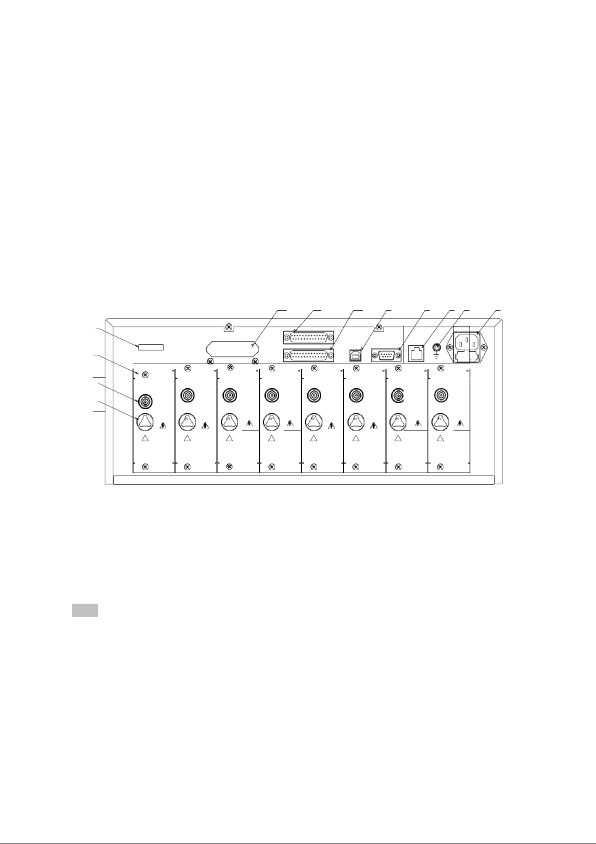
3.2 Rear Panel
Figure 3-2 gives a brief description of the rear panel.
12
11
10
9
8 7 6 5
2
贴标签
PAR8
PAR7
GPIB
USB
PAR6 PAR5 PAR4
PAR3
RS-23
2C
LAN
PAR2
PAR1
3
RTN/LOW
RTN/LOW
RTN/LOW
RTN/LOW
RTN/LOW
RTN/LOW
RTN/LOW
RTN/LOW
4
OUTPUT
OUTPUT
OUTPUT
OUTPUT
OUTPUT
OUTPUT
OUTPUT
OUTPUT
!
!
!
!
!
!
!
!
3.2.1 Product Name PlateFigure 3-2 Rear panel description
Information code for product model and date of manufacture
3.2.2 Test unit output module
Parallel high-voltage output control module, 8 for ST9010 and 4 for ST9010A. Each module is
independent of each other and can test a single DUT.
Note: Do not connect different test units to the same DUT, otherwise there will be unpredictable
risks.
3.2.3 Testlow terminal, test current return terminal (one per test unit)
Test low terminal of parallel high voltage test interface; all test low terminals have loop ground,
please pay attention to distinguish when conducting parallel test wiring. Wrong connection will cause
wrong judgment of the instrument and unpredictable risk.

◇15
3.2.4 High voltage output terminal (one per test unit)
High voltage output terminal of high voltage test interface.
3.2.5 Power socket: self-contained fuse box
For input AC power, please use the voltage within the specified input voltage range of the instrument.
Please use the power cord that comes with the instrument.
3.2.6 Protective ground terminal
The three-pin power socket that is plugged into the instrument power supply cannot guarantee reliable
connection to the earth, and then it must be connected to a reliable ground bar from here.
Note: Do not use the instrument without connecting to the ground. Otherwise, the instrument
chassis may be charged and there is a danger of electric shock.
3.2.7 LAN Interface
LAN communication interface to communicate with the computer.
3.2.8 RS232C serial interface
Serial communication interface to communicate with the computer. See Chapter 6 for the
communication command set.
3.2.9 USB serial communication interface
To communicate with the computer, the computer can control the instrument with the control
instruction set through this interface. See Chapter 6 for the communication command set.
3.2.10 HANDLER interface
Control and output interface for connecting the instrument to external control devices, there are
default mode and custom function mode, some pin functions can be customized.
3.2.11 SINGLE interface
Interface for outputting dedicated signals, currently used to connect multiple scan controllers
3.3 Multi-unit scanner description
Multi-channel scanners are equipped with multiple connection ports for each unit, used to connect
multi-port products, in order to implement product multi-parameter testing. ST90101 is compatible
with ST9010 and ST90101A with ST9010A.
Front panel picture:

◇16
3.3.1 UNIT n: Unit n
Input unit indication, light on indicates that the current unit of the host is working. An erected row of
output ports is the scan terminal of the same port.
3.3.2 CH n: scan channel n
Scan channel connection indication, the red light indicates that this channel is connected to the high
voltage input of the unit input; the green light indicates this channel is connected to the current
feedback input of the unit input.
Note: One output of the controller is a double-wire output.
If you need to implement the CK (Contact Check) function, you need to connect the two ends to two
different contact points on the same pin of the DUT, or can be connected to different pins connected
via small impedance.
If you do not need to implement the CK (Contact Check) function, the withstanding voltage
between the two wires of the same channel does not exceed 100V, please do not apply a high
voltage signal here to avoid danger.
Rear panel picture:

◇17
3.3.3 SIGNAL IN/OUT: Control signal input (female) / output (male)
Control uses series control and the input terminal is connected to the host or the output signal that is
switched through the controller. The output terminal is used to connect to the signal input terminal of
the next controller, to achieve control signal switch.
3.3.4 UNIT n INPUT/OUTPUT: Unit n input / output
The input is connected to the output high voltage and current sampling of the corresponding unit of
the host. The output is used to connect the input high voltage and current sampling of the
corresponding unit of the next controller to realize the switching of the test voltage and current. The
input / output terminals of the test voltage are actually connected inside the instrument and can be
used interchangeably. The same is true for the current terminal.
3.3.5 Power Input
Connect the mains power supply to 100~240AC, 47-60Hz.
3.4 Instrument Performance Overview
The ST9010/A can provide 8/4 parallel test withstand voltage units, and the test units are independent
of each other. The 8/4 unit means 8/4 times the safety test speed.
ST90101/A scan controller can extend 4 scan channels per test unit, and the ST9010/A can control
up to 4 units. Used to connect test products with test endpoints no larger than 16. By connecting the
matching test fixtures, the multi-parameter test can be completed once the product is placed.
The output of each test unit is the same: 5kVAC/10mA withstand voltage, 6kVDC/5mA withstand
voltage, 1kVDC/5mA insulation resistance test.
Note: Each unit of test product must be strictly isolated. The reasons are as follows:
Because one point in the test low end of each unit structure is connected to the ground. Current is
collected between the low end of the test and ground. The current loop of the high voltage of
adjacent units can be achieved through the low end of the other units. The effect of this current on
the measurement is as follows:
1. This current flows through the current sample, the current sample value of this path is counted.
2. This current is the ground current, two loop ground current misjudgments occur when GFI is
turned on.
3. This current is too large to cause SHORT protection of the high voltage source and current

◇18
sampling circuit HI FAIL
The following is a detailed description of the test unit parameters:
The principle structure of the test unit: The high voltage module is a DA reference, controllable
sine generator, PWM amplifier, 40 ~ 600Hz high voltage transformer boost, output voltage closed-
loop control loop.
1. DA reference: Ensure that the output voltage amplitude can be programmed.
2. Controllable sine generator: it can be set to work at 50 or 60Hz when AC output, no longer
limited by line voltage.
3. PWM power amplifier: high efficiency, good output performance and high sensitivity.
4. 40 ~ 600Hz high voltage transformer boost: for the power supply ripple problem of DC and
Insulation Resistance test, this instrument produces 600Hz AC power, after rectification, a DC
voltage is formed as a power source, to ensure that the DC power supply ripple is much smaller
than the previous regulator type old withstand voltage meter
5. Output voltage closed-loop control: The load regulation rate is small and the test data is
reliable.
Instrument software: multi-parameter continuous test, a variety of PC control functions.
ST9010 series are equipped with HANDLER, RS-232C, and USB, enabling the instrument to adapt
to a variety of automated test systems that require high safety and reliability.
Test unit features:
Four test functions—AC withstand voltage test, DC withstand voltage test, insulation
resistance test, open short detection When connected to the load, the instrument can
continuously perform multi-parameter testing by editing the test file.
Multi-unit scanning channel function (optional controller)
ST9010/A with multi-channel controller ST90101/A can realize 4, 8, 12, 16 programmable
scanning channels. Work with suitable test fixtures, programmable fast connection of
components can be realized, the test speed of multi-parameter measurements can be multiplied.
Node connection check CK: The scan channel of the scan controller is a two-wire parallel
structure, when the two-point connection is realized through the pin of the DUT, the
instrument performs the test of the connection reliability of the test node by performing the
continuity test.
Test power
Each high voltage module of the ST9010 series is a PWM power amplifier circuit and a 50VA
high voltage transformer, to achieve AC: 5kV/10mA, DC: 6kV/5mA output, the distortion of
the waveform is less than 3%. If the customer need to continuous current output, in order to
ensure the reliability of the instrument, maximum output time is 60 seconds when working
above 60% of rated output current. Within 60% to 40% of the rated output current, please pay
attention to the continuous working time. Continuous operation is guaranteed below 40% of
rated output current.

◇19
Figure 3-3 AC voltage load regulation
DC withstand voltage test 6kV/5mA
ST9010 Series provides DC withstand voltage test over a wide voltage range (maximum output
DC 6kV). Automatic voltage adjustment of 600Hz frequency hardware, voltage load regulation
rate ≤1%+10V.
6.00
5.00
4.00
3.00
2.00
1.00
0.00 0
1 2 3 4 5
Figure 3-4 ST9010/A DC Voltage Output Range
Insulation resistance test 0.050kV to 1.000kV (1V resolution) / 0.1MΩ to 10.0GΩ, the
maximum rated current is 5mA
Insulation resistance test range:
When the voltage is less than 500V: 0.1MΩ ~ 100MΩ Accuracy is ± [10% reading + 5 digits]
When the voltage is greater than 500V: 1MΩ ~ 100MΩ range accuracy is ± (5% reading + 5
digits), 100MΩ ~ 1GΩ range accuracy is ± (10% reading + 5 digits).
Open short circuit detection: Before starting high voltage, please determine whether or
the DUT is reliable connected, to ensure that the high voltage test is accurate and safe.
Open short circuit detection can determine the distributed impedance current above 100PF, less
than this value; the resolution of the current acquisition circuit of the instrument cannot
accurately distinguish the open circuit and the test component connection.
RS-232C interface as standard
Except power conversion, key lock, other functions can be remotely controlled. Test
conditions such as test voltage, judgment function, and test time in DC withstand voltage test,

◇20
AC withstand voltage test, and insulation resistance test can be remotely controlled. Test
results can also be read from behind through remote control. The USB and RS-232C
interfaces provide a stable and standardized standard test interface with PCs or otherdevices.
HANDLER interface for easy connection control
HANDLER interface: You can input START, STOP signal, and output TEST, PASS, FAIL
signals. Can be connected to the foot switch easily, connect with simple test fixtures for safety
interlocks, pneumatic controls, test indications, and more. Internal or external 24V power
supply can be used as the output interface power supply for easy control and connection.
USB interface for backup
The instrument is equipped with a USB interface, which can save the test files written by the
instrument and customer measurement files to an external USB flash drive, or load the files
from a USB to the instrument to conveniently set the usage parameters and archiving scheme
of the instrument in batches.
Test waiting time setting
The test waiting time can be set from 0.1s to 999.9s with a resolution of 0.1s. During this time,
the instrument will output a test control signal to control the external device to ensure reliable
test connection, and then start the high voltage test process.
Rise time control function
In AC withstand voltage test, DC withstand voltage test and insulation resistance test, the test
voltage can slowly rise to the set value instead of providing the set voltage to the DUT
immediately after starting the test. The voltage rise timecan be set from 0.1s to 999.9s with a
resolution of 0.1s. ST9010 series meets various UL test standards and IEC withstand voltage
test standards. (Rise time can be specified when the initial voltage is less than half of the test
voltage and when the set test voltage is reached).
Drop time control function
In the qualification judgment of the AC withstand voltage test, the test voltage can be
gradually reduced. The voltage drop time can be set between 0.1s and 999.9s with a resolution
of 0.1s.
Discharge function
Usually the tested part is capacitive. At the moment when the DC withstand voltage test and
the insulation resistance test are cut off, the DUT remains fully charged, therefore there is a
danger of electric shock. The ST9010 series has a forced fast discharge function on the DUT
after the DC withstand voltage test and insulation resistance test are completed.
Enhanced security
For improving safety, the ST9010 Series is equipped with many facilities and safety features,
include safety outputs, discharge function and ground current detection. The so-called ground
current detection is that when the return current of the ground high voltage test circuit is
greater than 0.5mA through the chassis, high voltage output is cut off.
Higher test accuracy
ST9010 series voltage digital display, voltage test accuracy is ± (1% reading + 5V) during
withstand voltage test, voltage accuracy is ± (2% reading + 5V) during insulation resistance
test. The accuracy in the withstand voltage and current test is ± (2% reading + 5 digits).
Current clear function
AC and DC withstand voltage test requires high voltage and high current sensitivity, the
This manual suits for next models
2
Table of contents
Other Sourcetronic Test Equipment manuals

Sourcetronic
Sourcetronic ST9201 Series User manual

Sourcetronic
Sourcetronic ST2523 User manual

Sourcetronic
Sourcetronic TM-25R User manual

Sourcetronic
Sourcetronic ST2883-5 User manual

Sourcetronic
Sourcetronic MD-5060 Series User manual

Sourcetronic
Sourcetronic MD-5075 Series User manual

Sourcetronic
Sourcetronic ST2826 User manual

Sourcetronic
Sourcetronic ST9110/A User manual

Sourcetronic
Sourcetronic ST2883 Series User manual


