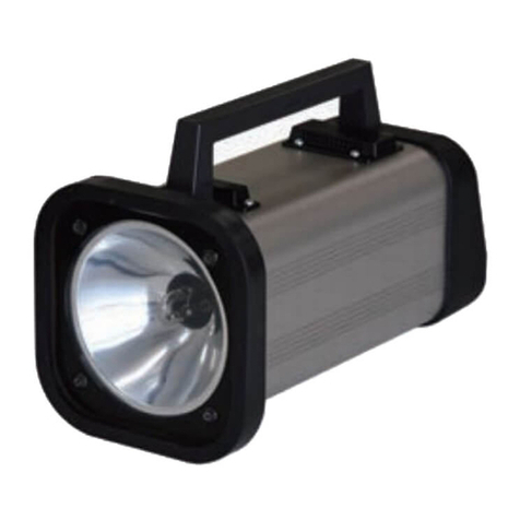
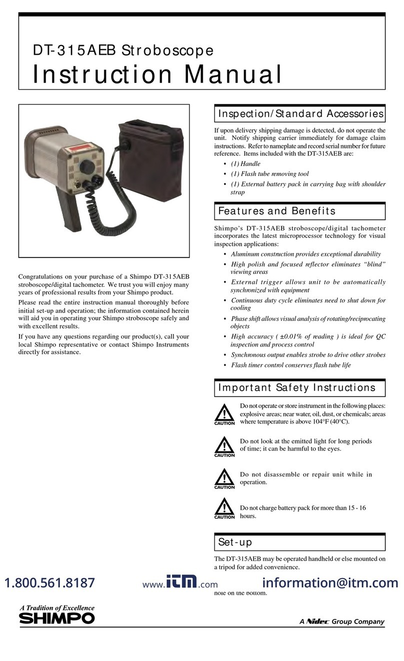
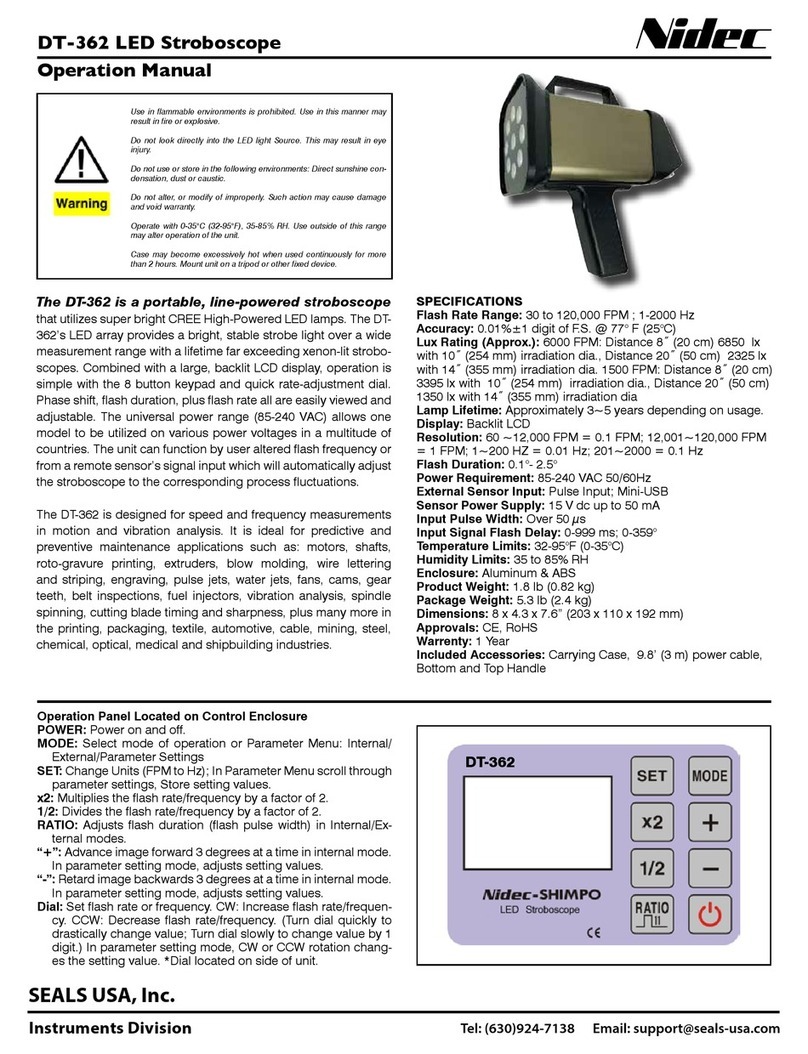
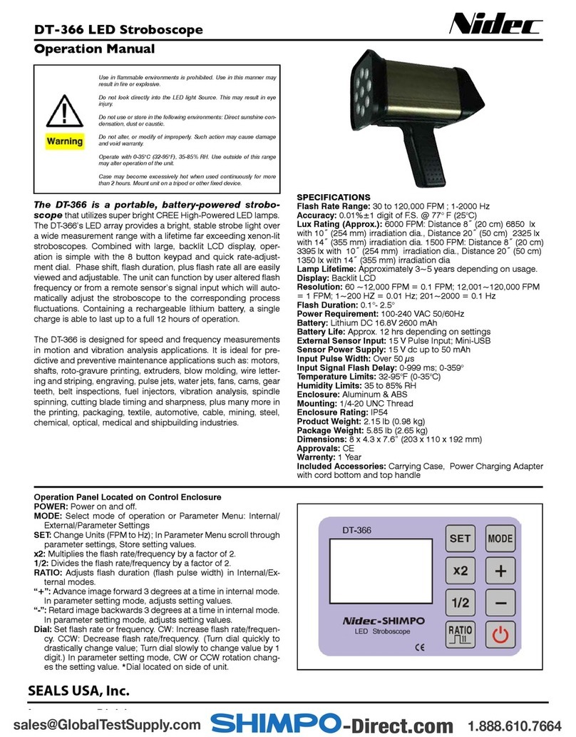
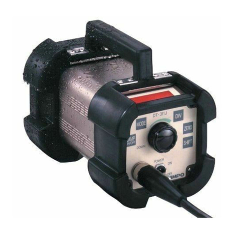
Nidec DT-3011P User manual

97751D
STROBOSCOPE
DT-3011P
Readthismanualthoroughlybeforeuse.
Beforeuse,pleasecarefullyreadthesesafetyprecautionsaswellasinstructions,
andfollowthemforproperoperation.
www.nidec.com/jp/nidec-shimpo
INSTRUCTION MANUAL

1
Besuretoreadtheentireinstructionmanualthoroughlybeforeinitialset-up,operationandmaintenance.
The instruction manual provides two grades of safety warnings: “Danger” and “Caution”.
Eachofthemisanimportantdescriptionrelatedtosafety.Besuretoobserve.
This indicates the possibility of fire, severe injury, and even death if a user disregards the instruction
andoperatestheunitimproperly.
Thisindicatesthepossibilityofminorinjuryorpropertydamageifauseroperatestheunitimproperly.
However,dependingonthecircumstances,thereisstillthepossibilitythatsevereinjurymayresult.
Besuretoobserve.
We categorize the type of those precautions using the following symbols throughout the
manual.
Aprohibitedactionyoumustnotdo.
Aforcedactionyoumustalwaysdo.
Neveruseinflammableenvironments.
Mayresultinfire.
Neverlookdirectlyintothelightsource.
Mayresultineyeinjury.
Donotapplystrongimpacttotheunit,
ordropit.
Failuretofollowthiscouldresultinabnormal
operation.
Avoidthefollowings.
Water,directsunlight,condensation,dust,dirt, salt,
iron,oil,chemicals,corrosiveand/orcombustible
gases.
Donotalter,modifyordisposeimproperly.
Failuretofollowthiscouldresultininjurydueto
abnormaloperation.
Operatewithin0-35°C(32-95°F)
Failuretofollowthiscouldresultinmalfunction.
Wipecleantheunitwithasoftdryclothifitgetsdirty.
Or immersea clothin water diluted neutral detergent,
wringit,andwipecleantheunitwithit.
Do not use any volatile chemicals, such as benzine,
thinner,oralcohol.
Operatewithin35-85%RH
Failure tofollowthiscouldresultinmalfunction.
Since continuously emitting light for long time causes
the unit’s housing to heat up, fix the strobe using a
tripod,etc.(Avoiddirectskincontactwiththeunit,such
asholdingitbyhand).
Failuretofollowthiscouldresultinmildburns.
Danger
Caution
Caution
Danger
Be sure to observe
Safety Precautions

2
Contents
1Overviewofthisproduct......................................................................... 3
2Beforeuse..................................................................................... 3
2.1Checkingthesupplieditems ..................................................................... 3
2.2Howtotakeon/offtheGrip....................................................................... 4
2.3HowtoputontheRubbercover .................................................................. 4
3Partnamesandfunctions........................................................................ 4
3.1Mainunit...................................................................................... 4
3.2OperationPanel................................................................................ 5
3.3Display ....................................................................................... 6
3.3.1Partnamesandfunctioninstructions........................................................... 6
4Functionsandoperations........................................................................ 7
4.1PowerON/OFF................................................................................. 7
4.1.1LAMPON/OFF ............................................................................ 8
4.1.2Flashtimer ................................................................................ 8
4.1.3HeatLampIndicator ........................................................................ 8
4.2Emissionmodeandsettings ..................................................................... 9
4.2.1HowtoswitchINTandEXT .................................................................. 9
4.3Internaloscillationemission..................................................................... 10
4.3.1FPMmodesetting(INT)..................................................................... 10
4.3.2PHAmode(INT)........................................................................... 12
4.4Externalsynchronousemission ................................................................. 13
4.4.1FPMmodesetting(EXT).................................................................... 14
4.4.2PHAmodesetting(EXT).................................................................... 15
4.5Functionmode................................................................................ 16
4.5.1Thesettingitems.......................................................................... 16
4.5.2Instructionsaboutfunctionmode ............................................................ 17
4.6Savingfunction ............................................................................... 23
4.6.1Savingthesettingvalues ................................................................... 23
4.6.2Howtosavethesettingvalues............................................................... 24
4.6.3Initialize.................................................................................. 25
4.6.4Initializingthesettingvalues................................................................. 26
4.7 Readingmemoryfunction..................................................................... 27
4.7.1Readingvalues ........................................................................... 27
4.7.2Howtoreadthememory.................................................................... 27
4.8ExternalsignalI/OconnectorspecificationsandPinassignment...................................... 28
4.9Externalpulseinput............................................................................ 29
4.10Externalpulseoutput ......................................................................... 29
4.11Lampreplacement............................................................................ 30
5Specifications................................................................................. 31
5.1Specificationslist.............................................................................. 31
5.2Externaldimensions........................................................................... 32
6Troubleshooting............................................................................... 33
3
1Overviewofthisproduct
A stroboscope tachometer is a measurement instrument to measure the speed (cycle) of rotating objects that rotate at a
constant speed, or moving objects that repeatedly operate at aconstant cycle.Whenthe rotation (motion) cyclematches with
the flash cycle whilethe strobe flash is periodically applied on a rotating or moving object, the rotating (moving) object image
appearstostandstill.Thisstroboscopetachometeristhenon-contacttype,andcanbeusedtoreadtheobjectfrequencywhen
such a still image appears. Also, a stroboscope can be used to make images of rotating or moving objects stand still or that
slightlymoveinordertoobservetheirappearanceinslow-motion.
Mainfeatures
●Wideflashrange–30to3000 FPM(flashesperminute)
●Emissioninsynchronizationwiththeexternaltriggerpulse
●PhaseShiftfunction.(PHAmode)
●Sealedstructuretopreventwateranddustfromentering.
2Beforeuse
2.1Checkingthesupplieditems
Checkthatthesixitemsbelowaresupplied.
DT-3011N
Mainunit
One(1)DT-3011P(withPowercable5m)
Accessories
One(1)Grip
One(1)Rubbercover
One(1)ExternalsignalI/Oconnector(8pins)
RM15WTPZ-8S
InstructionManual
One(1)Thisdocument
Warranty
One(1)document

4
2.2Howtotakeon/offtheGrip
2.3HowtoputontheRubbercover
3Partnamesandfunctions
3.1Mainunit
PleaseputontheGrip(oneof includedaccessories)beforeuse.
Insertthescrewintothehollonthebottomofmainunit,
andturntheknobcrockwisetotightenthescrew.
Thiscanbeattachedtothetripodforcameras.
Pleaseusetheonehasadesignatedscrew.
*1/4-20UNCunder8mmlong
XenonLamp
PowerSwitch
PowerCable
OperationPanel
ExternalsignalI/Oconnector
Bodybuttom
Screwhole
fortheGrip
Grip
Knob
PleaseputontheRubbercover(oneofincludedaccessories)beforeuse.
Fit the groove inside the rubber cover with the outer plastic frame on the
frontofthemainunit,andattachit.
*Donotpullthecoverforcibly.
Itmaycausedamage.

5
3.2OperationPanel
No.
Key
FunctionInstructions
①
PowerSwitch
TurnsthepowerON/OFF
②
Dial(LAMPPOWER)
Turnthisclockwiseorcounterclockwisetochangetheemissionfrequencyandsome
settingvalue.
PressandholdthecenterofthistoturnthelampON/OFF.
③
MODE
PressthistoswitchtheLEDdisplayasfollows
FlashesPerMinutemode(FPMmode) →PhaseShiftmode (PHAmodeDEG=
delayangle ) → Phase Shift mode ( PHA mode ms = delay time ) →FPM mode →…
④
LOAD(SAVE)
Pressthistoloadthesavedsettings.
Also,Pressandholdthistosavethecurrentdisplayandmodesettings.
⑤
SIG
SelectInternal/ External/ Parametermode.
Internaloscillation emission (referred to as “INT” ):Flashbyinternalsignal
External synchronous emission (referred to as “EXT”):Synchronizedflashwithexternal
signal
⑥
UNIT
Eachpressofthisswitchesthedelaytypeasfollowing,
delay angle(DEG) → delay time(ms) → DEG → ms
⑦
×2
PressthiswhileonINTtodoublethecurrentsetemissioncount(frequency).
(*Ifthedoublecountisoverthantheflashrange,nothingwillchangeonthedisplay.)
⑧
÷2
PressthiswhileonINTtohalvethecurrentsetemissioncount(frequency).
(*Ifthehalfcountislowerthantheflashrange,nothingwillchangeonthedisplay.)
②
①
③
④
⑧
⑥
⑦
⑤

6
3.3Display
3.3.1Partnamesandfunctioninstructions.
No.
Key
Display
Instructions
①
Emissionsettingdisplay
Each press of “SIG” switches emission settings.
INT :Internaloscillationemission
EXT:Externalsynchronousemission
②
Modedisplay
Each press of “MODE” switches flashing mode and delay type.
FPM:Flashesperminutesmode / PHA:Phasemode
③
SELECTnumberdisplay
12345
Thisindicatesthememoriesforsaving.(calledSELECTnumber)
Each press of “LOAD” switches SELECT number (1 to 5)
④
Numericaldisplay
StandardOperation:indicatesflashrate.
PHAMode:AngleandTimearedisplayed.
FunctionMode:Eachsettingvalueisindicated.
⑤
Delaytypedisplay
Each press of “MODE” switches flashing mode and delay type.
DEG:delayangle / ms:delaytime(millisecond)
⑥
Heatlamp
WhentheambienttemperatureoftheXenonlamprisesabovea
certainlevel,thislampindicatorwillflash.
⑥Heatlamp
④Numericaldisplay
③SELECTnumberdisplay
⑤Delaytypedisplay
②Modedisplay
①Emissionsettingdisplay
HEAT
INT
DEG
EXT
FPM
PHA
ms
1
2
3
4
5
×2
UNIT
MEM
SIG
LOAD
SAVE
MODE
÷2
DEG
INT
HEAT
EXT
FPM
PHA
ms

7
4Functionsandoperations
4.1PowerON/OFF
PressthepowerswitchwhenthepowerisOFFtoturnthepowerON.
WhenpoweristurnedON,themodelisindicated,followedbyinternaloscillationemissionorexternalsynchronousemission.
Operation
Display
When the power is
OFF
Pressthepower
switch
PressthepowerswitchwhenthepowerisONtoturnthepowerOFF,thentheindicationgoesoff.
Operation
Display
WhenthepowerisON
Pressthepowerswitch
*WhenthepoweristurnedON,thefollowingindicationmaybedisplayed.
Thefollowingindicationisanerrormessagewhenthereadingpreviouslyusedsettingvaluefails.
Press the “MODE” to return to normal emission screen from the error message display.
Operation
Display
Press the “×2”
Displayed“dt” for0.5sec.
When turning the power on for the first time, “EXT FPM
mode”isdisplayed.Fromthesecondtimeon,thesameas
whenthepowerispreviouslyturnedOFFisdisplayed.
Displayedthemodelforasec.
Returnstothenormalemissionscreen
Indicatedlettersgooff
Errormessage

8
4.1.1LAMPON/OFF
PressandholdthecenterofthedialtoturnONtheLAMPwhenemissionsettingisdisplayedonthescreen.
PressandholdagainwhileflashingtoturnOFFtheLAMP.
*WhenturningthepowerswitchOFFwhileflashing,itwillbeturnedONflashingatthenexttime.
4.1.2Flashtimer
WhentheFlashtimerissettoavalueotherthan0[minutes]inFunctionmode3,
theflashingwillautomaticallyceaseaftersettimefromthestartofthelightemission.
When the flashing stops by this flash timer, the display indicates “OFF”.
Pressandholdthedialtoreturntothepreviousdisplay.
4.1.3HeatLampIndicator
WhentheambienttemperatureoftheXenonlamprisesaboveacertainlevel,theHeatLampIndicatorwillflash.
If thetemperaturerisesmore,theHeatLampIndicatorwill remainonand thelightemissionwillcease.
*Thetemperaturetendstorisemorequicklythehighertheemissionfrequencyisset.
TheambienttemperatureoftheXenonlamp
HEAT
Lightemission
Lessthan75°C(164°F)
Off
Keepflashing
Over75°C(167°F)
Flash
Keepflashing
Over80°C(176°F)
On
Stopflashing
Operation
Display
Pressandhold
Operation
Display
Pressandhold
Pressandholdthedialtoflash.
Pressandholdagaintostopflashing.
Returntothepreviousdisplay
Aftersettimefromthestart

9
4.2Emissionmodeandsettings
Emissionmode
詳細
Internal oscillation emission ( “INT” )
Flashatthesetfrequency.
External synchronous emission ( “ EXT” )
Flashinsynchronizationwiththeexternaltriggerpulse.
Functionmode
Configurethesettings.
4.2.1HowtoswitchINTandEXT
Eachpressof “SIG” switches “INT” and “EXT”.
PowerOFF
OFF
Displaysthemodel
PowerON
FPMmode
INT
PHAmode
PHAmode
Savingfunction
Readthesavedvalue.(SELECTnumber)
EXT
Pressandhold
Confirmsaving ⇒Returntothepreviousdisplay
FPMmode
Displayexternalinputpulsefrequency
Confirmsaving ⇒
Returntothepreviousdisplay
Turnthedial
Increase/decrease
theemissioncount(frequency)
Turnthedial
Increase/decrease
thedelayangleorthedelaytime
Turnthedial
Increase/decrease
thedelayangleorthedelaytime

10
4.3Internaloscillationemission
・On “INT”, the Xenon lamp flashes at the displayed emission count.
・”INT” has thefollowing2modesettings.
Modesettings
FPMmode
PHAmode
Instructions
Set the emission count per minute
[FPM](flashesperminute)
Shiftthetimingofflash.
The phase can be changed by a
degreeoramillisecond.
(Onecycleis360°)
DisplayofINT
4.3.1FPMmodesetting(INT)
Theemissioncount(frequency)canbesetinFPMmode.
TurnthedialinaCWdirectiontoincreasetheemissioncount,andinaCCWdirectiontodecreaseit.
(Turnthedialfasttochangethesettingvaluegreatly,andslowlytochangeitslightly.)
Operation
Display
Increase/decrease
Theemissioncount
(frequency)
Press “SIG” to
switch to the “EXT”
CW
Decrease
Minimumvalueis30
CCW
Increase
Maximumvalueis3000
INT
EXT
Modedisplay
Theemissioncount(frequency)
Display“INT”
SELECTnumber

11
Press “×2”to double
the current set the
emissioncount
Press “÷2”to halve
the current set the
emissioncount
Press “MODE” to
switchtoPHAmode
FPMmode
PHAmode
*Ifitisoverthantheflashrange,
nothingwillchangeonthedisplay.
*Ifitislowerthantheflashrange,
nothingwillchangeonthedisplay.

12
4.3.2PHAmode(INT)
Whentherotation(motion)cycleofameasuredobjectmatcheswiththestrobeflashcycle,
themeasuredobjectappearstostandstill.UsethePHAmodeinordertoadjustthestopangle(position).
Thephasecanbechangedby1°usingdialwithintherangebetween1°and359°inthePHAmode.
Press “UNIT” to switch to PHA mode (ms).
(Thephasecanbechangedby0.01[ms]withintherangebetween0.00and999.99[ms]andby0.1[ms]withintherange
between1000.0and1994.4[ms].)
Atimelongerthanthelightemissioncyclecannotbeset.(PHAmodems)
Press “MODE” in PHA mode to switchtoFPMmode.
Operation
Display
Increase/decrease
Delayangle/time
Each press of “UNIT”
switchesDEGtoms
Press “MODE” to switch
toFPMmode
Decreasedelayangle
Increasedelayangle
PHAmode(ms)
CCW
CW
CCW
CW
PHAmode
FPMmode
PHAmode(DEG)
Decreasedelaytime
Increasedelaytime

13
4.4Externalsynchronousemission
・Externalsynchronousemissionisthefunctiontoemitastrobeflashinsynchronizationwithanexternaltriggerpulseinput.
・Youcansetwhichedgeoftheexternaltriggerpulsetriggersemission,therisingedgeorfallingedge.
・Atiming(delay)fromtheexternaltriggerpulseinputwiththestrobeflashemissioncanbeoptionallysetusingtimeandangle.
・EXThasthefollowing2modesettings.
Modesetting
FPMmode
PHAmode
Instruction
Display the measured value of the
emissioncount(frequency).
TheunitisFPM(flashesperminute)
Shiftthetimingofflash.
The phase can be changed by a
degreeoramillisecond.
(Onecycleis360°)
*Iftheexternaltriggerpulsecycleisbeyondthespecificationsrange,thefollowinglettersareindicated.
[Withoutthedelayangle/timesetting]
Measurablerange27to3300[fpm]
[Withthedelayanglesetting]
Measurablerange27to3300[fpm]
[Withthedelaytimesetting]
Measurablerange27to3300[fpm]
Modedisplay
Display “EXT”
SELECTnumber
Measuredvalueofthe
emissioncount(frequency)
Whentheexternalinputpulsefrequencygoesbelow27[fpm],
underlinesaredisplayed.
Whentheexternalinputpulsefrequencygoesbelow27[fpm],
anunderlineonthefirst,lefttwodigitsisdisplayed.
Whentheexternalinputpulsefrequencygoesbelow27[fpm],
anunderlineonthefirst,lefttwodigitsisdisplayed.
Whentheexternalinputpulsefrequencygoesbeyond3300[fpm],
overlinesaredisplayed.
Whentheexternalinputpulsefrequencygoesbeyond3300[fpm],
anoverlineonthefirst,lefttwodigitsisdisplayed.
Whentheexternalinputpulsefrequencygoesbeyond3300[fpm],
anoverlineonthefirst,lefttwodigitsisdisplayed.

14
4.4.1FPMmodesetting(EXT)
Operation
Display
Press “MODE” to
switchtoPHAmode
Press “SIG” to switch
toINT
INTFPMmode
PHAmode
Displayinthepreviousunit
(DEGorms)
EXTFPMmode

15
4.4.2PHAmodesetting(EXT)
Delayemissioncanbesetwithintheinputsignalrangebetween27and3300[fpm].
In the PHAmode, the phasefrom the external trigger pulse entry to strobeflash emission can be changed by 1° using the dial
withintherangebetween1°and359°.
Press “UNIT” to toggle between PHA mode (DEG) and PHA mode (ms).
The phasecanbechangedby 0.01[ms] withinthe rangebetween 0.00 and999.99[ms],by 0.1 [ms] withintherangebetween
1000.0and2216.0[ms].
Atimelongerthanthelightemissioncyclecannotbeset.(PHAmodems)
Press “MODE” in PHA mode to switch toFPMmode.
Operation
Display
Increase/decrease
Delayangle/time
Press “UNIT” to toggle
betweenDEGandms
Press “MODE” to
switchtoFPMmode
Decreasedelayangle
Increasedelayangle
CCW
CW
CCW
CW
PHAmode
FPMmode
Decreasedelayangle
Increasedelayangle

16
4.5Functionmode
TurnthepowerONwhile pressing the “MODE” to enter the function mode.
Duringthefunctionmode,turnthedial(CW/CCW)tochangethesettings.
And press “MODE” to save the setting and move to the next setting item. (F1⇒F2⇒F3⇒F4⇒F5⇒F6end)
IfthepoweristurnedOFFinthemiddleofthefunctionmode,thechangedvaluewillnotbesavedinthememory.
4.5.1Thesettingitems
Thesettingitemsinthefollowingtablecanbeconfiguredinthefunctionmode.
F1
Set toadddecimalpoint(forINT andEXTFPMmode)
Add decimal point
No decimal point
F2
Triggeredgesetting(forEXT)
Flashintherisingedge.
Flashinthefallingedge.
F3
Auto emissionstoptimesetting
Emissionisperformedcontinuously
Stopemissionautomaticallywhennooperationisperformedforacertainperiodoftime
and display “OFF”.
The availablesettingtimeiswithintherange between 0[min]and120 [min],
whichcan be changedby1 [ms]
F4
Choosetheinputcircuit
Opencollectorinput
Voltagepulseinput
F5
Measurementrangesetting(forINT)
Themaximumvalueof theemissioncountcanbesetwithintherangebetween30and3000[fpm]
(Thevalueislimitedtothemaximum.)
F6
Set thepulsewidthofthesynchronousoutputsignalto400 [µs] or150 [µs]
The pulse widthis400[µs]
The pulse widthis150[µs]

17
4.5.2Instructionsaboutfunctionmode
Howtomovetofunctionmode.
TurnthepowerONwhilepressingthe“MODE” to enter the function mode.
Operation
Display
ThepowerswitchON
while pressing “MODE”
Infunctionmode1,youcansetweathertoadddecimalpoint.(NotreflectedonEXT)
Operation
Display
Change
thesettingvalue
Goto
functionmode2
TurnthepowerON
while pressing “MODE”
Displays “Func” fortwoseconds
Andmovetofunctionmode1
Indicatesalternately
Gotofunctionmode2
*Previoussettingvalue
Thedefaultsettingis“0.0
CCW
CW
CCW:0(adddecimalpoint)
CW:0.0(nodecimalpoint)
Turnthedialanditwillstop
indicatingalternately.

18
Infunctionmode2,inwhichtheedgeoftheexternalpulsetriggersemission,therisingedgeorfallingedge,canbeset(forEXT).
Operation
Display
Change
thesettingvalue
Goto
functionmode3
*Thissettingchangesthetimingofemissionasshowninthefollowingfigure.
Indicatesalternately
Gotofunctionmode3
*Previoussettingvalue
The default setting is “L-H”
CCW:L-H(Risingedge)
CW:H-L(Fallingedge)
Turnthedialanditwillstop
indicatingalternately.
CCW
CW
● The timing of emission
Externaltriggerpulse
Flashattherisingedge
Flashatthefallingedge

19
Infunctionmode3,autoemissionstoptimecanbe changed.
Operation
Display
Change
thesettingvalue
Goto
functionmode4
Indicatesalternately
*Previoussettingvale
Thedefaultsettingis“0”
CCW
CW
Turnthedialanditwillstop
indicatingalternately.
CW:+1
CCW:-1
Thetimercanbesetbetween0[min]and120[min]
Gotofunctionmode4
Table of contents
Other Nidec Test Equipment manuals

Nidec
Nidec TNC Series User manual

Nidec
Nidec TTC Series User manual

Nidec
Nidec Shimpo DT-311J-230V User manual

Nidec
Nidec ST-5000 User manual

Nidec
Nidec Shimpo 329BL User manual

Nidec
Nidec DT-3015P User manual

Nidec
Nidec DT-725 User manual

Nidec
Nidec ST-5100 User manual

Nidec
Nidec DT-362 User manual

Nidec
Nidec Shimpo DT-315AEB-NIST User manual