Haseman Electric RS-10PM User manual

HASEMAN ELECTRIC
RS-10PM
USER MANUAL
Haseman RS-10PM is 10-channel, DIN Rail, Relay
module with true RMS energy meter, produced y
using Z-Wave Plus, the latest version of Z-Wave.
WHAT IS Z-WAVE?
Z-Wave is international standard protocol for
wireless communication in smart homes and
uildings.
Z-Wave ena les smart home products to talk to
each other. This creates the ack one of your
smart home and ena les you to use your
smartphone or ta let to create one-touch scenes
that help with daily activities like: saving energy,
keeping your home secure and eing more
comforta le.
Z-Wave technology is simple: each transmitted
message is reconfirmed (2-way communication)
and every mains powered device can act as a
repeater for other devices (mesh network). The
more Z-Wave products you have in your smart
home, the stronger your smart home network is.
Z-Wave technology is the leading solution in smart
home automation. There is a wide range of Z-Wave
devices that are compati le, independently of the
manufacturer. It gives the system the a ility to
evolve and expand over time.
SAFETY INFORMATION
Read this manual efore attempting to install the
device! Failure to o serve recommendations
included in this manual may e dangerous or cause
a violation of the law.
The manufacturer will not e held responsi le for
any loss or damage resulting from not following the
instructions of operating manual.
DANGER OF ELECTROCUTION!
All works on the device may e performed
only y a qualified and licensed electrician.
O serve national regulations.
The device is designed to operate in electrical
home installation. Faulty connection or use may
result in fire or electric shock.
Even when the device is turned off, voltage may
e present at its terminals.
Any maintenance introducing changes into the
configuration of connections or the load must e
always performed with disa led fuse.
CONNECTION DIAGRAMS
When connecting the module, o serve the
proper Neutral (N) and Line (L) terminals.
Only the provided current clamp can e
connected to Input terminals CT1 and CT2.
Each relay channel has its own Input (In)
and Output (O), which allows controlling of
devices, supplied y different voltages (12,
24, 48VDC / VAC, 110-240 VAC, etc.)
INSTALLATION
Mount the module on standard DIN Rail.
Connect the controlled lines. Depending on the
load supply voltage, use one of the following
connection diagrams:
For 2 0 VAC Loads:
For low voltage AC/DC Loads:
During operation, each channel
status is indicated y panel
indication LED.
Connect the local control lines S1 to S10 (
if local
control is used).
Depending on the BUTTON TYPE
Parameter (separate for each Channel), Push
Buttons or Toggle Switches can e connected:
Only Voltage Free contacts must e
connected etween terminal Com and
terminals S1 to S10.
Connect the Current clamp to inputs CT1-CT2 and
fix it on the monitored power line.
Connect the supply to Neutral and Line terminals
and wait for 30 second until the module
initialization
process is completed.

Z-WAVE NETWORK
Z-Wave uses a mesh network topology where any
non- attery powered device acts as a signal
repeater, ena ling relia le connections from one
node to the other. Battery powered devices do not
act as repeaters as this would result in high levels
of attery drain.
The frequencies used for Z-Wave are elow that of
the normal Wi-Fi and and this ena les etter
penetration of walls and other items found in all
homes, ut in addition to this, the mesh network
means that the transferred data can intelligently
routed y the network to get around o stacles and
there y o taining ro ust whole-home coverage.
Z-Wave typically has a range of a out 50 meters in
open air. However walls and other items in the
home will considera ly reduce this and therefore it
is recommended that the maximum device spacing
Z-Wave network is around 10 meters. Anything
closer will provide etter communications.
In order to have a hierarchy within a wireless
network, various types of Z-Wave device are
specified:
Controller: As the name implies, these devices are
those that control other Z-Wave devices. Controller
devices are factory programmed with a Home ID
which cannot e changed y the user.
Slave: Slave devices are those that are controlled
y controllers. Slave devices do not have a pre-
programmed Home ID, ut instead they take the
Home ID assigned to them y the Z-Wave network
controller.
Routing slave: This form of Z-Wave slave is one
that knows its neigh ors and has partial knowledge
of routing ta le. It can reply to the node from
which it has received the message. It can also send
unsolicited messages to a num er of predefined
nodes to which it has routes.
Z-Wave networks can e linked together for even
larger deployments. Each Z-Wave network can
support up to 232 Z-Wave devices allowing the
flexi ility to provide sufficient devices for a
complete automated home.
Z-WAVE NETWORK
INCLUSION / EXCLUSION
On factory default the device does not elong to
any Z-Wave network. The device needs to e
added to an existing wireless network to
communicate with the devices of this network. This
process is called Inclusion. Devices can also e
removed from the network. This process is called
Exclusion. Both processes are initiated y the
primary controller of the Z-Wave network. This
controller is turned into exclusion respective
inclusion mode. Inclusion and Exclusion is then
performed doing a special manual action right on
the device.
INCLUSION
Bring the module at max. 1 meter distance
from the main controller.
Connect the module to power supply.
Set the Z-Wave controller into INCLUSION
mode (adding new device to the Network).
Triple click the Z-Button on the front panel.
Be patient until the inclusion process is
completely finished. Multichannel
devices usually need a it more time
for complete configuration.
After the inclusion, it will appear a separate
instance (Node) for each relay channel as well as
additional nodes for the network Voltage, and
Frequency, Instant Current, Active Power, Power
Factor and Energy Usage. You can hide
unwanted Nodes and rename those which you
need. Depending on the model of your main
controller, you can also edit Node icons in order
to suit your current project needs.
EXCLUSION
Bring the module at max. 1 meter distance
from the main controller.
Connect the module to power supply.
Set the Z-Wave controller into EXCLUSION
mode (remove device from Z-Wave Network).
Triple click the Z-Button on the front panel.
After the EXCLUSION, all user
configuration parameters of the
module will e automatically set to
their default values.
CONFIGURATION PARAMETERS
This Z-Wave product is designed to work out of the
ox after inclusion. However certain configuration
can customize its functionality and fit it to your
specific project needs.
Configuration parameters are
accessi le from the main controller
User Interface (UI). You should find
detailed instruction on configuration
procedure into your main controller
User Manual.
When proceeding with parameter modification,
please refer to the parameter Range and Data
Type, as they are specified elow:
Reporting time
Minimum time interval etween power meter
data reports.
Parameter No: 11
Data type: 1 yte
Default value: 30 sec
Range: 1 – 255 sec
Decreasing the reporting time to less than
5 seconds could flood your Z-Wave
network, strongly impacting the network
communication.
Power Up Memory
When Power Up memory is active, the module will
save actual status of all outputs in case of power
reak. After restoring the supply, all outputs will e
switched to their previously saved statuses.
Parameter No: 64
Data type: 2 ytes
Default value: 0 (inactive)
Availa le Settings:
1 – Active
0 (or any other num er) - Inactive
Button Type (separate for each channel)
Parameters No: 65 to 74 (for Channel 1 to 10)
Data type: 2 ytes
Default value: 1
Availa le Settings:
1 – PUSH BUTTON (Each push is changing the
output status from ON to OFF, or vice versa).
2 – TOGGLE SWITCH (Each changing the
switch position will change the Output etween ON
and OFF statuses).
– FOLLOWER SWITCH (The output is
following the status of the switch: open switch –
inactive output, closed switch – active output).
ANY OTHER num er will disa le the local
control of this channel (remote control over the
Z-Wave network will remain active).

ASSOCIATIONS
Associations provide direct control of other
devices within the Z-Wave network, using the
switches, connected to the module inputs.
ASSOCIATION GROUPS:
Association Group 1 (Lifeline)
Reports state of the device.
The main Z-Wave+ network controller is added to
this group y default. It is not recommended to
modify this group.
Association Groups 2 to 10 (User Groups 1 to
9) are assigned to switches S1 to S9 respectively.
The module sends BASIC command class frame
(On/Off), following the state of the corresponding
Output 1 to Output 9 ( ehavior depends on the
value of the configuration parameter for the
Button Input type (parameter 65 to 73, individual
for each channel).
Association ensures direct transfer of
control commands etween devices, i.e.
it is performed without participation of
the main controller and requires
associated device to e in a direct range.
Sample configuration screens and module views in
Z-Way UI.
Sample configuration screens and module views
in Fi aro Home Center UI:
Configuring of polling time interval :
Sample views of RS10-PM power data in Fi aro
Home Center Energy Panels – (Current Energy
and Historical Data):
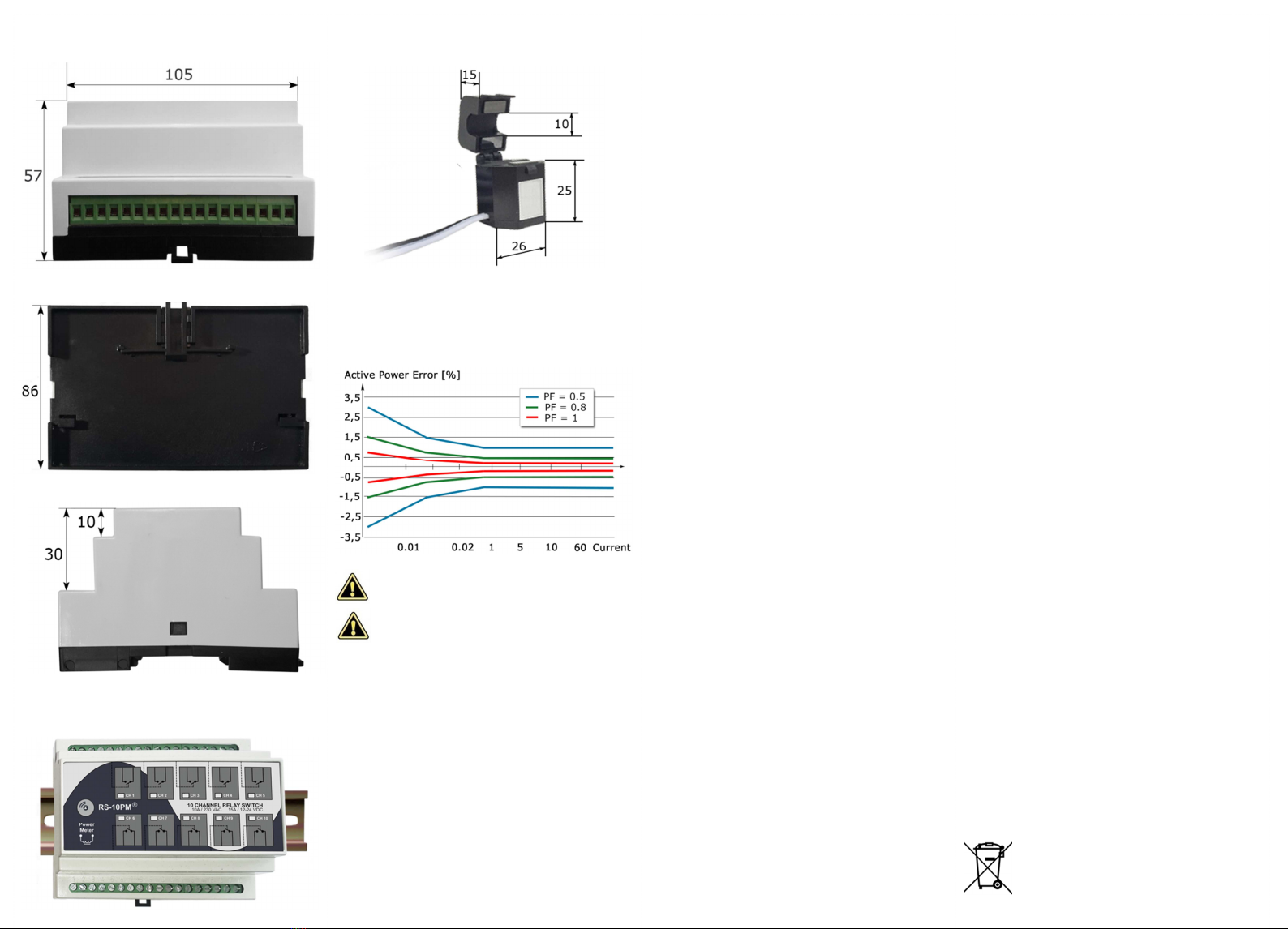
ENCLOSURE DIMENSIONS (mm)
DIN RAIL MOUNTING
CLAMP DIMENSIONS (mm)
ACCURACY
Power network parameters are measured out y the
most advanced True RMS measuring technology
assuring maximum accuracy and precision (±1% for
loads greater than 4.8W).
Power measurement takes into account all
actual fluctuations of the Mains voltage.
Energy Usage
data is saved into nonvolatile
memo
ry of the module at any 1 kWh and will
e automatically restored in case of power
reaks. After excluding the module from the Z-
Wave
network, Energy Usage record will reset to 0.
COMMAND CLASSES
• Basic • Switch Binary • Sensor Multilevel
• Meter • Association Group Information
• Device Reset Locally • Z-Wave Plus Info
• Multi Channel • Configuration
• Manufacturer Specific • Power Level
• Firmware Update • Association • Version
• Multi Channel Association
WARRANTY
We warrant that the device is free from defects in
parts and workmanship under normal use for 24
months from date of purchase. The original
purchase invoice or sales receipt is the proof of
date of purchase y the Customer.
If the Device has manufacturing defects or in any
case of alleged lack of conformity, the Customer
shall send a claim. Once we receive the Warranty
Claim, we must inform the Customer if the
Warranty is applica le and the address where the
Device shall e sent in order to verify the defects
(if any). The Device shall e sent y the Customer
at its own costs and expenses, and with the
original packaging, the supplied accessories and
documents proving date of purchase. We must
then inform the Customer a out the defects and on
its repair or replacement (where applica le). The
Warranty Period of the replaced or repaired Device
shall not e extended. We will ship the repaired or
a replaced Device to Customer freight prepaid. We
will not e lia le for damages to property caused
y faulty device. We will not e lia le for indirect,
incidental, special, consequential or punitive
damages, or for any damage, including, inter alia,
loss of profits, savings, data, loss of enefits,
claims y third parties and any property damage or
personal injuries arising from or related to the use
of the Device. If the Device cannot e replaced
with another of the same type (e.g. the Device is
no longer in production or no longer availa le for
selling in the Customer’s country), it may e
replaced with a different one having similar
technical specifications to the faulty one. Such
replacement shall e considered as a total
fulfillment of our o ligations.
Warranty exclusion:
- Defects caused y normal wear of parts or
especially su ject to wear, such as parts that
require periodic replacement during the normal
operation of the system;
- Splits, cracks, scratches, dents, scratched or
discolored surfaces and parts, reakage of plastic
parts and any other cosmetic damage;
- Damages resulting from use of the system other
than that provided, including ut not limited to the
failure to follow instructions contained in the
operating manual;
- Damages caused y accident, a use, misuse,
dirt, viruses, liquid contact, fire, earthquake,
improper or inadequate maintenance or cali ration,
negligence or other external causes;
- Environmental damage and / or defects caused
y smoke, dust, dirt, soot, or other external
influences;
- Damages caused y modifications and alterations
in the functionality or features;
- Damages resulting from transportation or
inadequate packaging when returning the product
to an authorize service center;
- Damages resulting from surges in the power
and/or telecommunication network, improper
connection to the grid in a manner inconsistent
with the operating manual, or from connecting
other devices not recommended y the maker;
- Damages caused y operating or storing the
device in extremely adverse conditions, i.e. high
humidity, dust, too low (freezing) or too high
am ient temperature;
- Products whose warranty sticker has een
removed, damaged or rendered illegi le;
- Expiration of the Warranty Period.
If a defect is not covered y the Warranty, we will
inform the Customer a out the extra expenses for
the repair or replacement.
TECHNICAL SPECIFICATIONS
10 Independent Relay Outputs
Capa le to control AC and/or DC loads
Wide Power Supply range: 110-240VAC, 50/60Hz
Max. AC output: 10A / 110-230V (resistive load)
Max. DC output: 12A / 12-30VDC
Dura le relays with long life contact system
16A rated PCB power tracks and terminals
Front panel LED indication of active outputs
User configura le Power Up Memory function
User configura le parameters for utton type –
push utton, toggle switch or follower switch
(individual setting for each channel)
True RMS Power meter with 60A current clamp
(included), reporting all power data to the Z-Wave
controller (True RMS Voltage, Frequency, Current,
Instant Active Power, Power Factor and Energy
Usage)
ABS enclosure for standard DIN Rail mounting
Dimensions: 105 x 86 x 57mm
Dura le tactile uttons on the front panel
Conforms to EU regulations: EN55022 EN610006
Radio protocol: Z-Wave Plus, GEN 5, 868.42MHz
Antenna range: up to 50m outdoor / 30m indoor
DISPOSAL GUIDELINES
The product does not contain hazardous chemicals.
Do not dispose of electrical appliances as
unsorted municipal waste, use separate
collection facilities. Contact your local
government for information regarding
the collection systems availa le.
Other Haseman Electric Relay manuals


