Microelettrica Scientifica MC2-30V User manual
MC2-30V
Doc. N° MO-0499-ING
Copyright 2019
Date
17.03.2022
Rev.
2
Pag.
1
of
63
MICROPROCESSOR
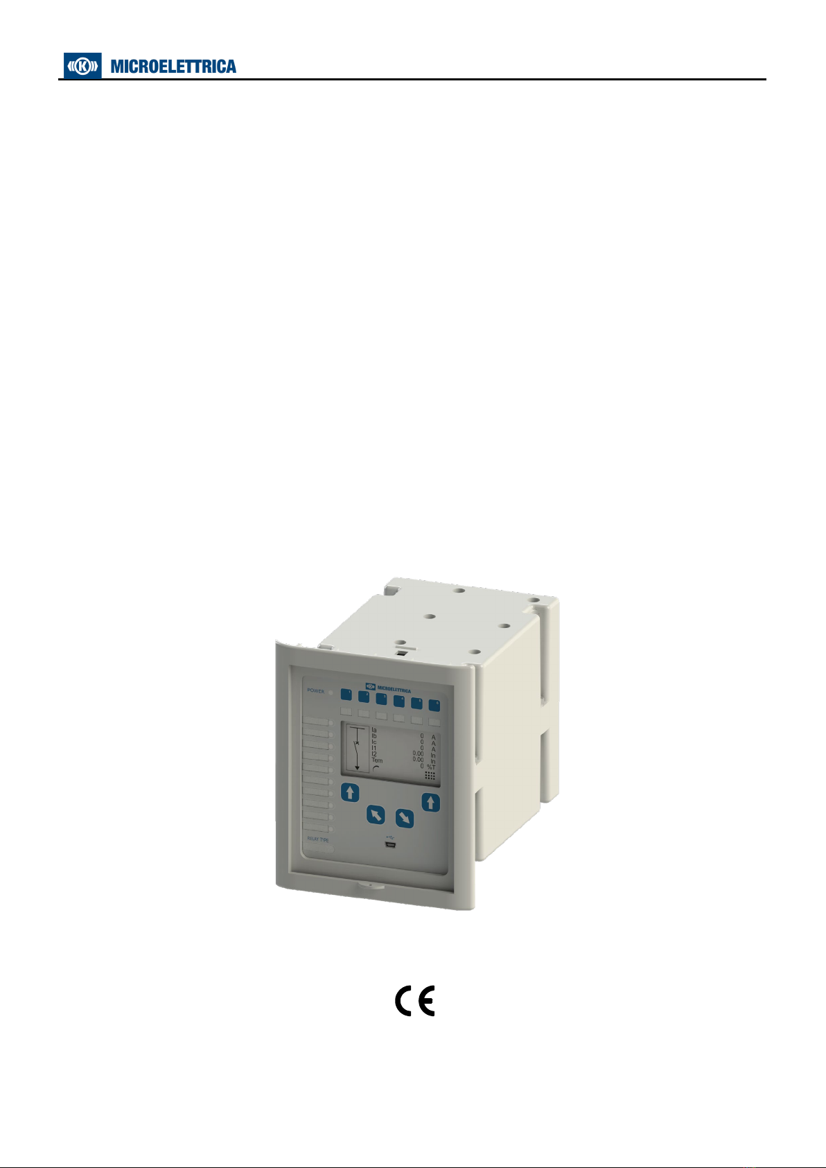
THREE PHASE VOLTAGE PROTECTION RELAY
WITH
ISLANDING DETECTION
TYPE
“MC2-30V”
OPERATION MANUAL

MC2-30V
Doc. N° MO-0499-ING
Copyright 2019
Date
17.03.2022
Rev.
2
Pag.
2
of
63
1. General Utilization and Commissioning Directions _________________________________________________________5
1.1 - Storage and Transportation _____________________________________________________________________5
1.2 - Installation __________________________________________________________________________________5
1.3 - Electrical Connection___________________________________________________________________________5
1.4 - Measuring Inputs and Power Supply_______________________________________________________________5
1.5 - Outputs Loading ______________________________________________________________________________5
1.6 - Protection Earthing ____________________________________________________________________________5
1.7 - Setting and Calibration _________________________________________________________________________5
1.8 - Safety Protection _____________________________________________________________________________5
1.9 - Handling ____________________________________________________________________________________5
1.10 - Maintenance ________________________________________________________________________________5
1.11 - Waste Disposal of Electrical & Electronic Equipment __________________________________________________5
1.12 - Fault Detection and Repair _____________________________________________________________________5
2. General _________________________________________________________________________________________6
2.1 - Power Supply ________________________________________________________________________________6
3. Front Panel ______________________________________________________________________________________6
4. Keyboard and Display ______________________________________________________________________________7
4.1 - Display _____________________________________________________________________________________7
5. Icons of Display ___________________________________________________________________________________8
6. Signalization _____________________________________________________________________________________9
6.1 - Leds Manual Reset ____________________________________________________________________________9
6.2 – Display of the last trip _________________________________________________________________________9
7. Leds Configuration________________________________________________________________________________10
7.1 - Name _____________________________________________________________________________________11
7.2 - Link enable _________________________________________________________________________________11
7.3 - Status _____________________________________________________________________________________11
7.4 - Light Prog. _________________________________________________________________________________11
7.5 - Funct. Mode ________________________________________________________________________________11
7.6 - Functions __________________________________________________________________________________11
7.7 - Table 1 ____________________________________________________________________________________12
7.8 - Example: Change settings for “Led1” _____________________________________________________________13
7.8.1 - “Link Enable” ____________________________________________________________________________13
7.8.2 - “Flashing” ______________________________________________________________________________13
7.8.3 - “Funct.Mode” ____________________________________________________________________________14
7.8.4 -“Functions” _____________________________________________________________________________14
8. User Variables ___________________________________________________________________________________15
8.1 - Name _____________________________________________________________________________________15
8.2 - User Descr. _________________________________________________________________________________15
8.3 - Linked functions _____________________________________________________________________________15
8.4 - OpLogic____________________________________________________________________________________15
8.5 - Timer _____________________________________________________________________________________15
8.6 - Timer type _________________________________________________________________________________15
8.7 – Extra _____________________________________________________________________________________15
8.8 - Logical status _______________________________________________________________________________15
8.9 - Example: Setting “User Variable” ________________________________________________________________15
8.9.1 - “User description” (User descr.) _____________________________________________________________16
8.9.2 - “Linked Functions”________________________________________________________________________16
8.9.3 - “Operation Logic” (Oplogic) _________________________________________________________________17
8.9.4 - “Timer” ________________________________________________________________________________17
8.9.5 - “Timer type” ____________________________________________________________________________18
8.9.6 - “Extra”_________________________________________________________________________________18
9. Local Commands _________________________________________________________________________________19
10. Measure_______________________________________________________________________________________20
11. Maximum Values ________________________________________________________________________________20
12. Trip Recording __________________________________________________________________________________21
13. Partial Counters _________________________________________________________________________________23
14. Total Counters __________________________________________________________________________________24
15. Events ________________________________________________________________________________________25
15.1 – Events on display ___________________________________________________________________________26
16. System (System parameters) ______________________________________________________________________27
17. Settings _______________________________________________________________________________________28
17.1 - Modifying the setting of variables _______________________________________________________________29
17.2 - Password _________________________________________________________________________________30
17.3 – Menu: Communic. (Communication) ___________________________________________________________31
17.3.1 – Description of variables___________________________________________________________________31
17.3.2 – Front Panel USB serial communication port (RS232) ____________________________________________31
17.3.3 – Cable for connection from Relay to Personal Computer __________________________________________31
17.3.4 – Main serial communication port (RS485) _____________________________________________________31
17.4 - Menu: Customise (Human Machine Interface) ____________________________________________________32
17.4.1 – Description of variables___________________________________________________________________32
17.5 - Function: FileSys (File system and Disk management) ______________________________________________33
17.5.1 - Description of variables ___________________________________________________________________33
17.5.2 – Download file informations ________________________________________________________________33
17.6 - Function: 1U> (First Overvoltage Element F59)____________________________________________________35

MC2-30V
Doc. N° MO-0499-ING
Copyright 2019
Date
17.03.2022
Rev.
2
Pag.
3
of
63
17.6.1 - Description of variables ___________________________________________________________________35
17.6.2 - Operation _____________________________________________________________________________35
17.7 – Function: 2U> (Second Overvoltage Element F59) _________________________________________________36
17.7.1 - Description of variables ___________________________________________________________________36
17.7.2 - Operation _____________________________________________________________________________36
17.8 - Function: 1U< (First Undercurrent Element F27) ___________________________________________________36
17.8.1 - Description of variables ___________________________________________________________________36
17.8.2 - Operation _____________________________________________________________________________36
17.9 - Function: 2U< (Second Undercurrent Element F27) ________________________________________________36
17.9.1 - Description of variables ___________________________________________________________________36
17.9.2 - Operation _____________________________________________________________________________36
17.10 - Function: 1f> (First Overfrequency Element F81>) ________________________________________________37
17.10.1 - Description of variables __________________________________________________________________37
17.10.2 - Operation ____________________________________________________________________________37
17.11 - Function: 2f> (Second Overfrequency Element F81>)______________________________________________37
17.11.1 - Description of variables __________________________________________________________________37
17.11.2 - Operation ____________________________________________________________________________37
17.12 - Function: 1f< (First Underfrequency Element F81<) _______________________________________________38
17.12.1 - Description of variables __________________________________________________________________38
17.12.2 - Operation ____________________________________________________________________________38
17.13 - Function: 2f< (Second Underfrequency Element F81<) _____________________________________________38
17.13.1 - Description of variables __________________________________________________________________38
17.13.2 - Operation ____________________________________________________________________________38
17.14 - Function: 1Uo> (First Zero Sequence Overvoltage Element F59Vo) ___________________________________39
17.14.1 - Description of variables __________________________________________________________________39
17.14.2 - Operation ____________________________________________________________________________39
17.15 - Function: 2Uo> (Second Zero Sequence Overvoltage Element F59Vo) _________________________________39
17.15.1 - Description of variables __________________________________________________________________39
17.15.2 - Operation ____________________________________________________________________________39
17.16 - Function: U1< (First Voltmetric unlock islanding detector Element F81v) _______________________________40
17.16.1 - Description of variables __________________________________________________________________40
17.16.2 - Operation ____________________________________________________________________________40
17.17 - Function: U2> (Second Voltmetric unlock islanding detector Element F81v) _____________________________40
17.17.1 - Description of variables __________________________________________________________________40
17.17.2 - Operation ____________________________________________________________________________40
17.18 - Function: 1df/dt (First Frequency rate of change Element)__________________________________________41
17.18.1 - Description of variables __________________________________________________________________41
17.18.2 - Operation ____________________________________________________________________________41
17.19 - Function: 2df/dt (Second Frequency rate of change Element) _______________________________________41
17.19.1 - Description of variables __________________________________________________________________41
17.19.2 - Operation ____________________________________________________________________________41
17.20 - Function: TCS (Trip Circuit Supervision)_________________________________________________________42
18.20.1 - Description of variables __________________________________________________________________42
17.20.2 - Operation ____________________________________________________________________________42
17.21 - Function: IRF (Internal Relay Fault)____________________________________________________________43
17.21.1 - Description of variables __________________________________________________________________43
17.21.2 - Operation ____________________________________________________________________________43
17.22 - Function: Oscillo (Oscillographic Recording) _____________________________________________________43
17.22.1 - Description of variables __________________________________________________________________43
17.22.2 - Operation ____________________________________________________________________________43
17.22.3 – Available on software ___________________________________________________________________44
17.22.4 – Setting “User Trigger Oscillo” _____________________________________________________________45
17.22.5 – Example: Setting “Oscillo Trigger Logic” _____________________________________________________46
17.23 - Function: CB Mngn (Control C/B) _____________________________________________________________49
17.23.1 - Description of variables __________________________________________________________________49
17.23.2 – Push-Buttons (Programmable only via software) ______________________________________________49
17.24 - Function: ExtResCfg (External Reset Configuration) _______________________________________________51
17.24.1 - Description of variables __________________________________________________________________51
18. Input – Output (via software)______________________________________________________________________51
18.1 – Digital Input _______________________________________________________________________________51
18.2 – “DI” Configuration (via software) _______________________________________________________________51
18.2.1 – Example ______________________________________________________________________________52
18.2.2 – Name ________________________________________________________________________________52
18.2.3 – Status ________________________________________________________________________________52
18.2.4 – Functions _____________________________________________________________________________52
18.2.5 – Example: Setting “Digital Input” ____________________________________________________________52
18.3 – Physical Outputs____________________________________________________________________________53
18.4 - “DO” Configuration __________________________________________________________________________53
18.4.1 - Example configuration ____________________________________________________________________53
18.4.2 - Functions - Operation Mode________________________________________________________________54
19. InfoStatus _____________________________________________________________________________________58
19.1 - Description of variables ______________________________________________________________________58
20. Date and Time __________________________________________________________________________________59
20.1- Clock synchronization ______________________________________________________________________60
22. Healthy (Diagnostic Information) ___________________________________________________________________61

MC2-30V
Doc. N° MO-0499-ING
Copyright 2019
Date
17.03.2022
Rev.
2
Pag.
4
of
63
23. Dev.Info (Relay Version) __________________________________________________________________________61
24. Maintenance ___________________________________________________________________________________61
25. Wiring Diagram _________________________________________________________________________________62
26. Overall Dimensions ______________________________________________________________________________62
27. Electrical Characteristics __________________________________________________________________________63

MC2-30V
Doc. N° MO-0499-ING
Copyright 2019
Date
17.03.2022
Rev.
2
Pag.
5
of
63
1. General Utilization and Commissioning Directions
Always make reference to the specific description of the product and to the Manufacturer's instruction.
Carefully observe the following warnings.
1.1 - Storage and Transportation
Must comply with the environmental conditions stated in the product's specification or by the applicable IEC
standards.
1.2 - Installation
Must be properly made and in compliance with the operational ambient conditions stated by the Manufacturer.
1.3 - Electrical Connection
Must be made strictly according to the wiring diagram supplied with the Product, to its electrical
characteristics and in compliance with the applicable standards particularly with reference to human safety.
1.4 - Measuring Inputs and Power Supply
Carefully check that the value of input quantities and power supply voltage are proper and within the
permissible variation limits.
1.5 - Outputs Loading
Must be compatible with their declared performance.
1.6 - Protection Earthing
When earthing is required, carefully check its effectiveness.
1.7 - Setting and Calibration
Carefully check the proper setting of the different functions according to the configuration of the protected
system, the safety regulations and the co-ordination with other equipment.
1.8 - Safety Protection
Carefully check that all safety means are correctly mounted, apply proper seals where required and
periodically check their integrity.
1.9 - Handling
Notwithstanding the highest practicable protection means used in designing electronic circuits, the electronic
components and semiconductor devices mounted on the modules can be seriously damaged by electrostatic
voltage discharge which can be experienced when handling the modules.
The damage caused by electrostatic discharge may not be immediately apparent but the design reliability and
the long life of the product will have been reduced. The electronic circuits are completely safe from
electrostatic discharge (8 KV IEC 255.22.2) when housed in their case; withdrawing the modules without
proper cautions expose them to the risk of damage.
1.10 - Maintenance
Make reference to the instruction manual of the Manufacturer; maintenance must be carried-out by specially
trained people and in strict conformity with the safety regulations.
1.11 - Waste Disposal of Electrical & Electronic Equipment
(Applicable throughout the European Union and other European countries with separate collection program).
This product should not be treated as household waste when you wish dispose of it. Instead, it should be
handed over to an applicable collection point for the recycling of electrical and electronic equipment.
By ensuring this product is disposed of correctly, you will help prevent potential negative consequence to the
environment and human health, which could otherwise be caused by inappropriate disposal of this product. The
recycling of materials will help to conserve natural resource.
1.12 - Fault Detection and Repair
Internal calibrations and components should not be altered or replaced.
For repair please ask the Manufacturer or its authorized Dealers.
Misapplication of the above warnings and instruction relieves the Manufacturer of any liability.
MC2-30V
Doc. N° MO-0499-ING
Copyright 2019
Date
17.03.2022
Rev.
2
Pag.
6
of
63
2. General
The main features of the relays are:
User friendly front face with hi-resolution graphic display (240x128), 10 signal Leds, 6 push-buttons
(configurable) and four push-button for complete local managemen, USB for local communication.
Eight user programmable Output Relays.
Eight opto-isolated, self powered Digital Inputs.
RS485 communication port (independent from the USB port on front panel)
2.1 - Power Supply
The relay can be fitted with two different types of power supply:
Type 1
24V(-20%) / 110V(+15%) a.c.
24V(-20%) / 125V(+20%) d.c.
Type 2
80V(-20%) / 220V(+15%) a.c.
90V(-20%) / 250V(+20%) d.c.
Before energizing the unit check that supply voltage is within the allowed limits.
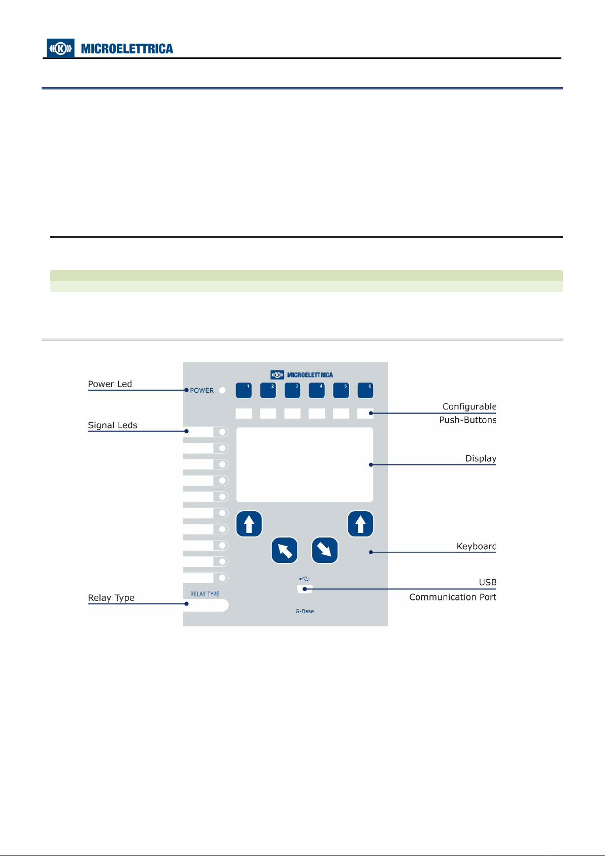
3. Front Panel
MC2-30V
Doc. N° MO-0499-ING
Copyright 2019
Date
17.03.2022
Rev.
2
Pag.
7
of
63
4. Keyboard and Display
Push-buttons Programmable
↓
Navigation
menu
By these buttons the options showed in
correspondence on the display are selected.
Increase These buttons are used to scroll the items of
the different menus (Local Control,
Measurements, Energy metering etc).
Decrease
By the key
select the windows showing the ICONS of the available menus.
By the key
,
select the desired icon and enter by key
The different elements can be selected by the key
and
.
The details of the individual menus are given in the following paragraphs.
4.1 - Display
The 240x128 pixel hi-resolution LCD display the available information (menu, etc.).
MC2-30V
Doc. N° MO-0499-ING
Copyright 2019
Date
17.03.2022
Rev.
2
Pag.
8
of
63
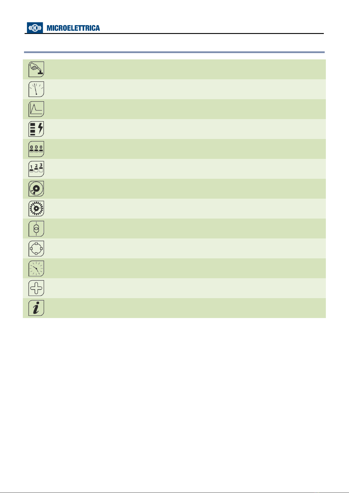
5. Icons of Display
LocalCmd Local Commands
Measure Actual Measurements
Max Val. Maximum Values
TripRec. Trip Recording
Counter Partial Counters (Resettable Counter)
ROCnt Total Counter (Read Only Counter)
Events Event Recording
Setting Function Settings
System System Settings
InfoStatus Information Status
TimeDate Time And Date
Healthy Diagnostic Information
Dev.Info Relay Version

MC2-30V
Doc. N° MO-0499-ING
Copyright 2019
Date
17.03.2022
Rev.
2
Pag.
9
of
63
6. Signalization
Eleven signal leds are provided:
1
Led Power Supply
Not programmable
Green
10
Leds
Programmable (via software)
N°
Colours
1
Green
2
Green
3
Green
4
Yellow
5
Red
6
Red
7
Red
8
Yellow
9
Red
10
Green
In case of auxiliary power supply failure the status of the leds is recorded and reproduced when power supply is
restored.
6.1 - Leds Manual Reset
For Leds manual reset operate as follows:
1
•
Press “Menu” for
access to the main
menu with icons.
3
•
Select
“LedClear”
•
Press “Select” to
execute the
command.
2
•
Select icon
“LocalCmd”.
4
•
When command has
been executed the
display shows
“Command Done”;
•
Press “Select”,
6.2 – Display of the last trip
Beside the signalization of the led “Trip”, indicating a generic function trip, the display shows a window
indicating the last function that was tripped and the number of events that are stored in the memory. The
display will show this window until the reset button or external reset are operated.
1
•
Press “Menu” to access to the main menu with icons.
Press “Home” to erase trip visualization.
Ex. “tTCS” (flashing) is the last trip.

MC2-30V
Doc. N° MO-0499-ING
Copyright 2019
Date
17.03.2022
Rev.
2
Pag.
10
of
63
7. Leds Configuration
The relay manage up to 10 signal leds (Programmable), 1 led “Power” (green).
For Leds programming (only via software) operate as follows:
- Open the software program and connect to the relay.
- Select “Change Windows” from “Menu” button (options)
- Select “Led Setting”
MC2-30V
Doc. N° MO-0499-ING
Copyright 2019
Date
17.03.2022
Rev.
2
Pag.
11
of
63
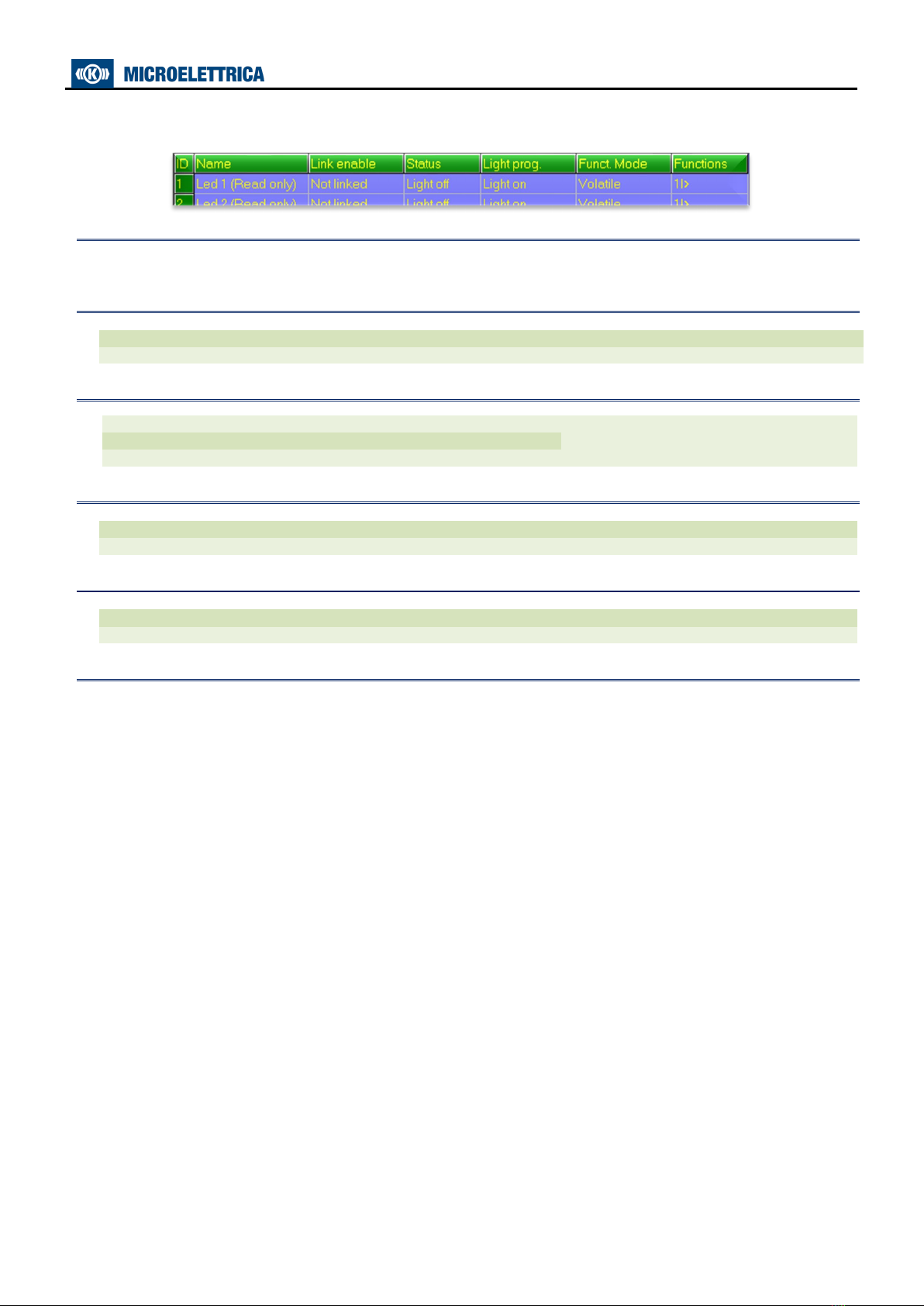
The window for leds configuration will show:
7.1 - Name
Led name – for leds position see picture
7.2 - Link enable
Linked
=
Enable to operate
Not Linked
=
Disable
7.3 - Status
7.4 - Light Prog.
Light-on
=
When cause appear led is illuminated
Flashing
=
When cause appear led is flashing
7.5 - Funct. Mode
Volatile
=
When cause disappear led turn-off (Not memorized)
Latched
=
When cause disappear led remain illuminated (memorized)
7.6 - Functions
Select the function assigned to specific led (see table 1).
It’s possible to configure only one function for each led.
For configuration multiple functions use “UserVar” function.
Light-off
=
Normal condition
Light-on
=
When cause appear led is illuminated
See “Light Prog”
Flashing
=
When cause appear led is flashing

MC2-30V
Doc. N° MO-0499-ING
Copyright 2019
Date
17.03.2022
Rev.
2
Pag.
12
of
63
7.7 - Table 1
1U>
Start
First overvoltage element
t1U>
Trip
2U>
Start
Second overvoltage element
t2U>
Trip
1U<
Start
First undervoltage element
t1U<
Trip
2U<
Start
Second undervoltage element
t2U<
Trip
1f>
Start
First overfrequency element
t1f>
Trip
2f>
Start
Second overfrequency element
t2f>
Trip
1f<
Start
First underfrequency element
t1f<
Trip
2f<
Start
Second underfrequency element
t2f<
Trip
1Uo>
Start
First zero sequence overvoltage element
2Uo>
Start
Second zero sequence overvoltage element
U1<
Start
First Voltmetric unlock islanding detector element
U2>
Start
Second Voltmetric unlock islanding detector element
1df/dt
Start
First Frequency rate of change element
2df/dt
Start
Second Frequency rate of change element
tTCS
Start
Trip coil supervision
IRF
Start
Internal Relay Failure
tIRF
Trip
DskClean
Disk near Full clean operation is required
DskFull
Disk Full Write should be lock
DskWR
Disk write in progress
DskFRMT
Disk Format in progress
DskCHK
Check disk in progress
manOpCmd
Manual Open Command
L/Rdisc
Local/Remote signal Discrepancy
CL-Cmd
Close Command
C/Bfail
Circuit Breaker failure
Gen.Start
Start
Generic
Gen.Trip
Trip
User Trigger Oscillo
User Variable for Oscillographic Recording
UserVar 0
User Variable
to
UserVar 24
Vcc
Reserved
Gnd
Reserved
ResetLog
Reset signal logic
P1
Push-button 1
P2
Push-button 2
P3
Push-button 3
P4
Push-button 4
P5
Push-button 5
P6
Push-button 6
0.D1
Digital Inputs
0.D1Not
to
0.D8
0.D8Not
0.R1
Output relays
0.R2
0.R3
0.R4
0.R5
0.R6
0.R7
0.R8
MC2-30V
Doc. N° MO-0499-ING
Copyright 2019
Date
17.03.2022
Rev.
2
Pag.
13
of
63
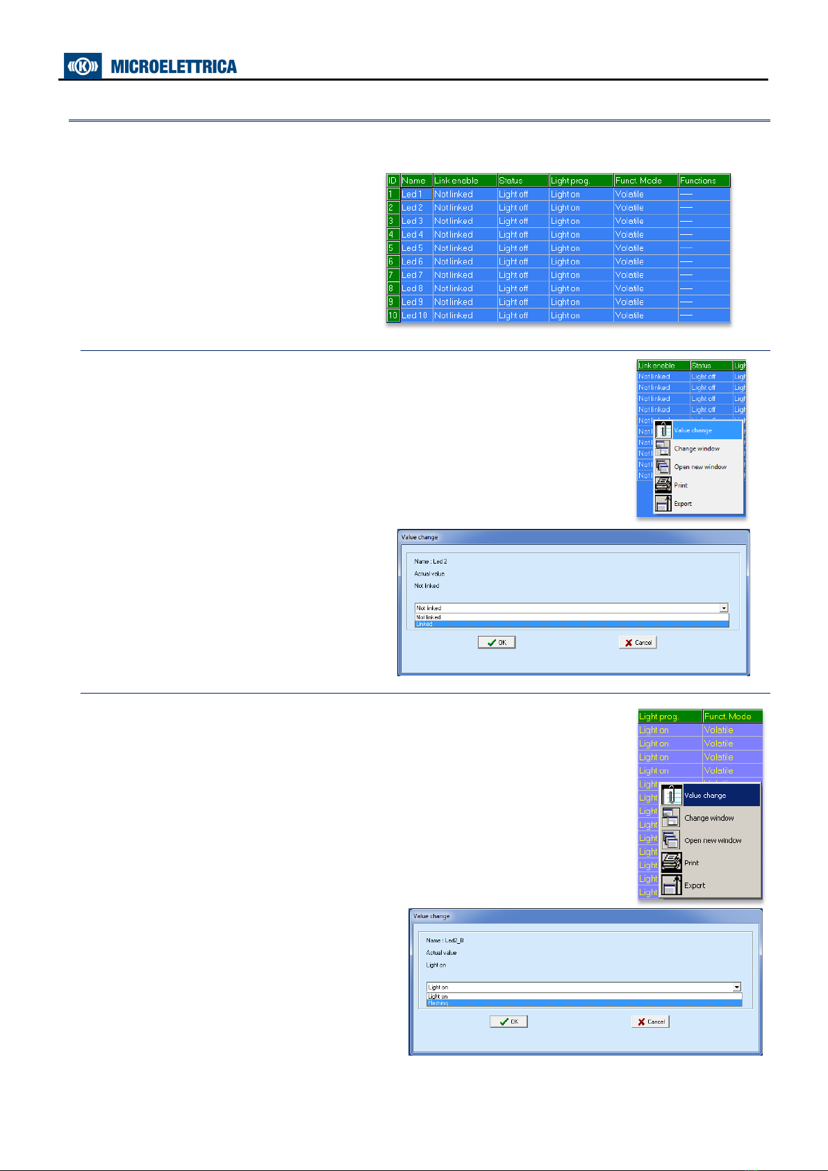
7.8 - Example: Change settings for “Led1”
Change settings for “Led1” : “Enable”, “Flashing”, “Latched”, “1U>”.
Main Windows:
7.8.1 - “Link Enable”
Select “Link enable” related to “Led 1” and press right button on mouse, select
“Value change”:
Select “Linked” and press “OK” (if Password is
request, see § Password):
7.8.2 - “Flashing”
Select “Light prog” related to Led 1 and press right button on mouse, select “Value
change”:
Select “Flashing” and press “OK” (if Password is
request, see § Password):

MC2-30V
Doc. N° MO-0499-ING
Copyright 2019
Date
17.03.2022
Rev.
2
Pag.
14
of
63
7.8.3 - “Funct.Mode”
Select “Funct.Mode” related to Led 1 and press right button on mouse, select
“Value change”:
Select “Latched” and press “OK”
(if Password is request, see § Password):
7.8.4 -“Functions”
Select “Functions” related to Led 1 and press right button on mouse,
select “Value change”:
Select “1U>” and press “OK”
(if Password is request, see § Password):
MC2-30V
Doc. N° MO-0499-ING
Copyright 2019
Date
17.03.2022
Rev.
2
Pag.
15
of
63
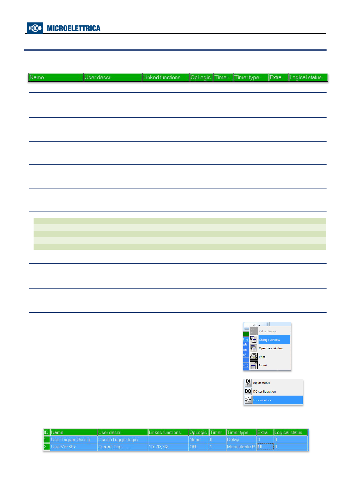
8. User Variables
The “User Variable” is a result of a logical operation (Or, AND, ecc...), it can be used like other logical output.
This operation is possible only via software.
8.1 - Name
Internal progressive name
8.2 - User Descr.
Custom identification label for user variable
8.3 - Linked functions
Selection functions
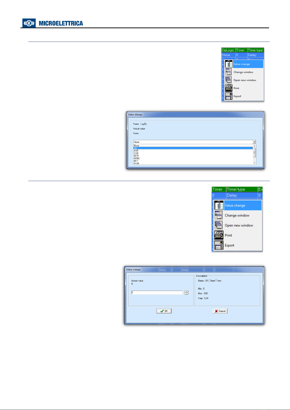
8.4 - OpLogic
Operation Logic
=
[None, OR, AND, XOR, NOR, NAND, NOT, Ff-SR, Counter, Rise-UP, Fall-Down]
8.5 - Timer
Time delay (0-600)s, step 0.01s
8.6 - Timer type
Delay
=
Add a delay on output activation. The “Timer” is edge triggered on rise edge.
Monostable P
=
Activated the output for the time “Timer”
Monostable N
=
Disactivated the output for the time "Timer".
Blinking
=
The output switches periodically at the frequency defined by "Timer".
Delay-Fall-Down
=
Delay-Fall-Down
8.7 – Extra
Extra Time (0 - 65000)s, step 1s
8.8 - Logical status
“User Variable” Logical status
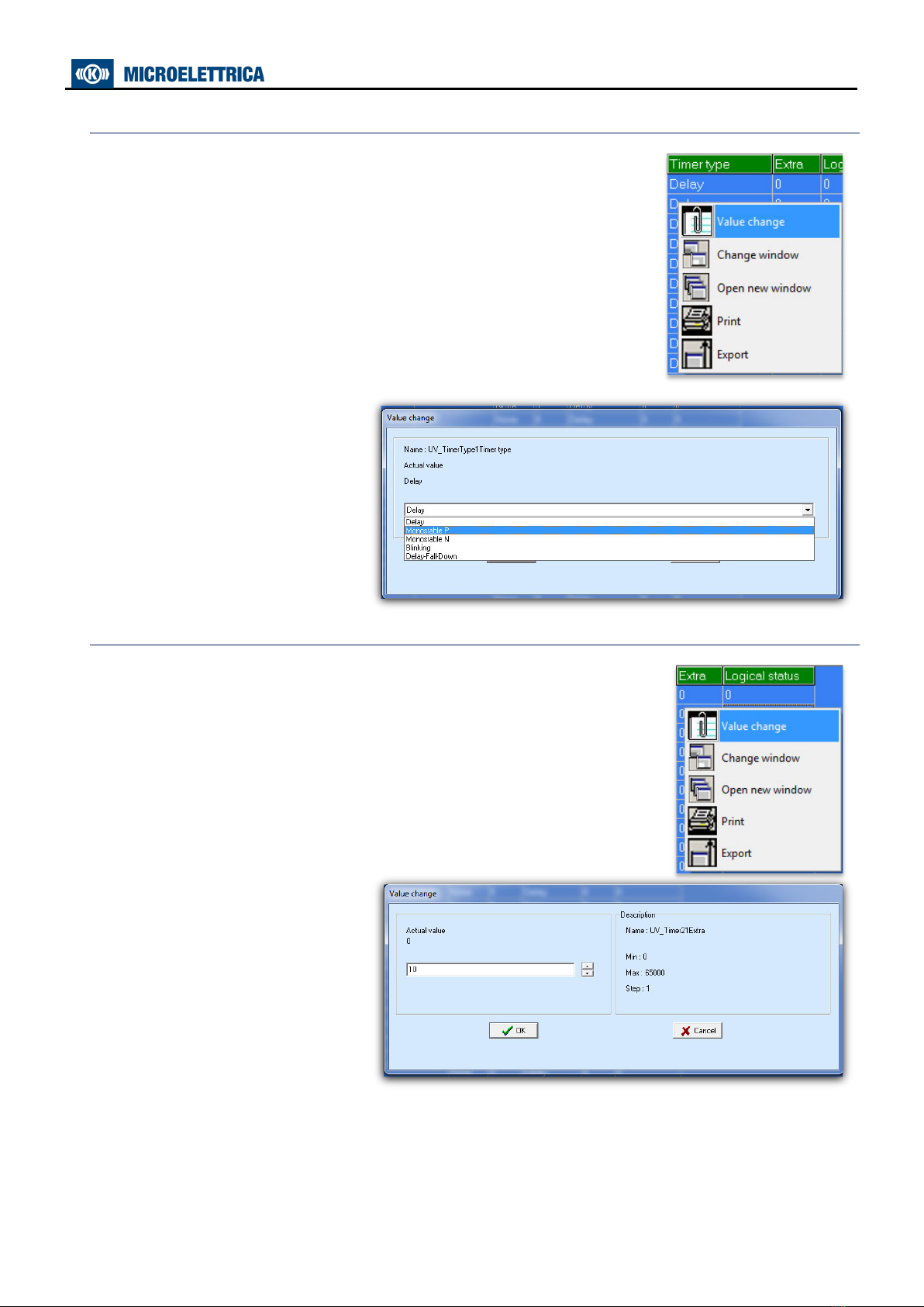
8.9 - Example: Setting “User Variable”
Open software program and connect to the relay.
Select “Change Windows” from “Menu” button
Select “User Variable”
Setting for “UserVar<0>” : “Voltage Trip”, “1U>,2U>”, “OR”, “1”, “Monostable P”, “10”.

MC2-30V
Doc. N° MO-0499-ING
Copyright 2019
Date
17.03.2022
Rev.
2
Pag.
16
of
63
8.9.1 - “User description” (User descr.)
Select “User descr” related to “UserVar<0>” and press right button on mouse,
select “Value change”:
Insert “Voltage Trip” into box and press
“OK”:
8.9.2 - “Linked Functions”
Select “Linked Functions” related to “UserVar<0>” and press right button on
mouse, select “Value change”:
Select “1U>, 2U>” from “Available” box via push-button “<Add”, and press “OK”.
For remove functions, use push-button “>Remove”.
MC2-30V
Doc. N° MO-0499-ING
Copyright 2019
Date
17.03.2022
Rev.
2
Pag.
17
of
63
8.9.3 - “Operation Logic” (Oplogic)
Select “Oper Logic” related to “UserVar<0>” and press right button on mouse,
select “Value change”:
Insert “OR” into box and press “OK”:
8.9.4 - “Timer”
Select “Timer” related to “UserVar<0>” and press right button on mouse,
select “Value change”:
Select “1” into box and press “OK”:
MC2-30V
Doc. N° MO-0499-ING
Copyright 2019
Date
17.03.2022
Rev.
2
Pag.
18
of
63
8.9.5 - “Timer type”
Select “Timer” related to “UserVar<0>” and press right button on mouse,
select “Value change”:
Select “Monostable P” into box and
press “OK”:
8.9.6 - “Extra”
Select “Extra” related to “UserVar<0>” and press right button on mouse,
Select “10” into box and press “OK”:

MC2-30V
Doc. N° MO-0499-ING
Copyright 2019
Date
17.03.2022
Rev.
2
Pag.
19
of
63
9. Local Commands
“Local Commands” allow to operate from relay front face controls like Thermal Memory reset, Leds reset, etc.
Menu
Description
Password
Led
Clear
Reset of signal Leds
No
Relays
Clear
Manual reset of output relays
No
main C/B
Cl.
Manual C/B closing (conditioned by Password)
Yes
main C/B
Op.
Manual C/B opening (conditioned by Password)
Yes
Event
Clear
Reset Events
Yes
LTrip
Clear
Reset Last Trip
Yes
Counter
Clear
Reset Counters
Yes
HistFail
Clear
Reset of Internal Failure Historic records
Yes
Leds
Test
Signal Leds test
No
Force
Osc
Force Oscillo Recording
Yes
Format
iDisk
Format internal disk
Yes
Check
iDisk
Check internal disk
Yes
To operate one command by the Front Face Keyboard, proceed as follows (Led Clear in the present example).
1
•Press “Menu” for access to the main menu with icons.
2
•Select “LocalCmd” icon with pushbutton “Increase” or “Decrease”.
•Press “Select” for access.
3
•Select with pushbutton “Increase” or “Decrease” the menu “LedClear”.
•Press “Select” to execute the command.
(if Password is request, see § Password).
4
•When command has been executed the display shows
“Command Done”; go to “3”.
MC2-30V
Doc. N° MO-0499-ING
Copyright 2019
Date
17.03.2022
Rev.
2
Pag.
20
of
63
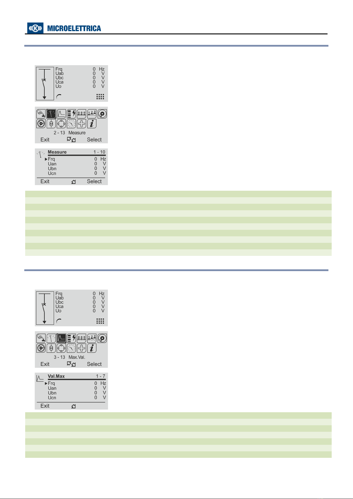
10. Measure
Real time values as measured during the normal operation.
1
•Press “Menu” for access to the main menu with icons.
2
•Select “Measure” icon with pushbutton “Increase” or “Decrease”.
•Press “Select” for access.
3
•Scroll the menu “Measure”with pushbutton “Increase” or
“Decrease” to display the measurement.
•Press “Exit” to go to the main menu.
Frq
(30 ÷70)
Hz
Frequency
Uan
(0 ÷99999)
V
Phase voltage A-N
Ubn
(0 ÷99999)
V
Phase voltage B-N
Ucn
(0 ÷99999)
V
Phase voltage C-N
Uab
(0 ÷99999)
V
Phase-to-voltage A-B
Ubc
(0 ÷99999)
V
Phase-to-voltage B-C
Uca
(0 ÷99999)
V
Phase-to-voltage C-A
Uo
(0 ÷99999)
V
Zero sequence voltage
V1
(0 ÷99999)
Vn
Positive sequence voltage
V2
(0 ÷99999)
Vn
Negative sequence voltage
11. Maximum Values
Maximum demand values recorded starting from 100ms after closing of main Circuit Breaker.
(updated any time the breaker closes).
1
•Press “Menu” for access to the main menu with icons.
2
•Select “Measure” icon with pushbutton “Increase” or “Decrease”.
•Press “Select” for access.
3
•Scroll the menu “Measure”with pushbutton “Increase” or
“Decrease” to display the measurement.
•Press “Exit” to go to the main menu.
Frq
(30 ÷70)
Hz
Frequency
Uan
(0 ÷99999)
V
Phase voltage A-N
Ubn
(0 ÷99999)
V
Phase voltage B-N
Ucn
(0 ÷99999)
V
Phase voltage C-N
Uo
(0 ÷99999)
V
Zero sequence voltage
V1
(0 ÷99999)
Vn
Positive sequencevoltage
V2
(0 ÷99999)
Vn
Negative sequence voltage
Table of contents
Other Microelettrica Scientifica Relay manuals


