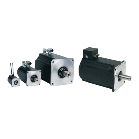
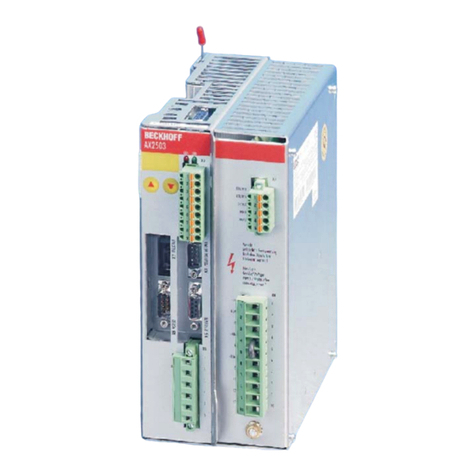
Haskel Q-Drive QGD Series User manual

88544_A
Q-Drive
Installation, Operation, and Maintenance Manual
Model: QGD and QGT

All trademarks used herein are the property of their respective owners.
© 2020 Haskel International, LLC. All Rights Reserved.
Haskel International, LLC
Telephone 818-843-4000
Website www.haskel.com
Email for Sales sales@haskel.com
Mailing Address: 100 East Graham Place
Burbank CA 91502 USA

iii
Contents
About This Product ........................................................................................................................................ v
Your Model Number and Serial Number ................................................................................................... v
Symbols in This Manual ............................................................................................................................ v
Limited Warranty ...................................................................................................................................... vi
Safety Instructions ......................................................................................................................................... 1
Warnings ....................................................................................................................................................... 1
Cautions ........................................................................................................................................................ 2
Safe Transport .............................................................................................................................................. 3
Lifting Instructions for Q-Drive ................................................................................................................... 3
Introduction.................................................................................................................................................... 5
Gas Section ............................................................................................................................................... 6
Q-Drive Actuator ........................................................................................................................................ 7
Coolant ...................................................................................................................................................... 7
Modes of Operation ................................................................................................................................... 7
Compressor Mode ........................................................................................................................... 7
Fill & Pause Mode ........................................................................................................................... 7
Fill & Stop Mode .............................................................................................................................. 7
User Interface ............................................................................................................................................ 7
User Accounts ................................................................................................................................. 7
Symbols on the Screen ................................................................................................................... 9
Performance ................................................................................................................................................ 11
Specifications .............................................................................................................................................. 11
Site Preparation and Inspection .................................................................................................................. 12
Installation and Setup .................................................................................................................................. 12
Securing the Q-Drive System .................................................................................................................. 13
Attaching Power Connections ................................................................................................................. 13
Attaching the Process Gas Filter ............................................................................................................. 13
Attaching Air, Gas, and Coolant Lines .................................................................................................... 14
Supplying the Oil for Lubrication ............................................................................................................. 15
Using Q-Drive System ................................................................................................................................. 16
Before You Begin .................................................................................................................................... 16
Powering On the System ......................................................................................................................... 16
Logging In to the HMI .............................................................................................................................. 17
Configuring the User Interface (UI) ......................................................................................................... 17
Running the Leak Test ............................................................................................................................ 19
Shutting Down the System ...................................................................................................................... 19
Purging the Gas Sections ........................................................................................................................ 19
Monitor the System ..................................................................................................................................... 21

iv
Monitoring the Gas Pressure at Inlet and Outlet ..................................................................................... 21
Monitoring the Gas Temperature ............................................................................................................ 22
Monitoring the Coolant Temperature ....................................................................................................... 22
Managing the System .............................................................................................................................. 22
About Alarms ............................................................................................................................................... 23
Troubleshooting .......................................................................................................................................... 25
Inspection and Preventive Maintenance ..................................................................................................... 26
Inspection Schedule ................................................................................................................................ 26
Checking the Surface and Connections .................................................................................................. 26
Running the Blow-By Test ....................................................................................................................... 26
Checking Oil ............................................................................................................................................ 27
Disassembling the Gas Section .............................................................................................................. 27
Performing a Visual Inspection ..................................................................................................... 28
Reassembling the Adapter Piece Assembly ................................................................................. 28
Reassembling the Gas Section ..................................................................................................... 34
Checklist for Inspection and Preventative Maintenance ......................................................................... 35
About Service and Repair ........................................................................................................................... 36
Ordering Replacement Parts ................................................................................................................... 37
Replacement Procedures ........................................................................................................................ 38
Re-Assembling Drive Rod Assembly ...................................................................................................... 38
Replacing the Piston Seals ..................................................................................................................... 40
Replacing Oil Filter and Oil ...................................................................................................................... 41
Removing the Oil Filters ................................................................................................................ 41
Installing New Oil Filters ................................................................................................................ 43
Draining Oil from Actuator ............................................................................................................. 44
Adding New Oil .............................................................................................................................. 45
Re-Assembling Drive Rod Assembly ...................................................................................................... 46
Replacing the Tie Rods ........................................................................................................................... 48
Replacing Check Valves.......................................................................................................................... 49
Replacing Cooling Jacket ........................................................................................................................ 50
Points of Connections ................................................................................................................................. 51
List of Alarms .............................................................................................................................................. 57
Errors ....................................................................................................................................................... 57
Warnings ................................................................................................................................................. 58
Information Message ............................................................................................................................... 59

v
About This Product
This manual describes how to install, operate, and maintain the following models of the Haskel Q-
Drive: Haskel, LLC reserves the right to make changes to the Q-Drive and its firmware that might not
be documented in this manual.
Model Type Diameter of Gas Section (mm)
First stage Second stage
QGT150-90
Two stage 150 90
QGT150-63 63
QGT90-63 90 63
QGD150
Double-acting
150 150
QGD90 90 90
QGD63 63 63
Your Model Number and Serial Number
In any service calls or to order parts, include the model, serial number, and firmware version. The
serial number is located on the right side of the frame and on the Settings page of the screen. The
Settings page also shows the current version of the system’s firmware.
Symbols in This Manual
Indicates conditions that can cause damage to the equipment.
Indicates conditions that can cause injury.
Disconnect Power Before Servicing
Identifies the manufacturer
Electrical Shock Hazard
Hot Surface Hazard
Lockout/Tagout before servicing
Model
Serial Number

vi
Requires forklift to move.
Use two people to lift the component.
Limited Warranty
Haskel International manufactured products are warranted free of original defects in material and
workmanship for a period of one year from date of shipment to first user.
This warranty does not include packaging, seals, or failures caused by lack of proper maintenance,
incompatible fluids, foreign materials in the driving media, in the pumped media, or application of
pressures beyond catalog ratings. Products believed to be originally defective may be returned,
freight prepaid, for repair and/or replacement to the distributer, authorized service representative or to
the factory, if upon inspection by the factory or authorized service representative the probem is found
to be origanally defective material or workmanship, repair or replacment will be made at no charge for
labor or material, F.O.B the point of repair or replacement.
Permission to return under warranty should be requested before shipment and include the following:
the original purchase date, purchase order number, serial number, model number, or other pertinent
data to estableish warranty claim, and to establish warranty claim, and to expedite the return or
replacement to the owner.
If unit has been disassembled and reassembled in a facility other than Haskel, warrranty is void if it
has been improperly reassembled or substitute parts have been used in place of factory-
manufactured part.
Any modification to any Haskel product which you have made or may make in the future has been
and will be at your sole risk and responsibility, and without Haskel approval or consent. Haskel
disclaims any all liability, obligation, or responsibility for the modified product, and for any claims,
demands, or causes of action for damage or for personal injuries resulting from the modification
and/or use or such a modified Haskel product.
HASKEL’S OBLIGATION WITH RESPECT TO ITS PRODUCTS SHALL BE LIMITED TO
REPLACEMENT, AND IN NO EVENT SHALL HASKEL BE LIABLE FOR ANY LOSS OR DAMAGE
CONSEQUENTIAL OR SPECIAL, OF WHATEVER KIND OR NATURE, OR ANY OTHER EXPENSE
WHICH MAY ARISE IN CONNECTION WITH OR AS A RESULT OF SUCH PRODUCTS OR THE
USE OR INCORPORATION THEREOF IN A JOB. THIS WARRANTY IS EXPRESSLY MADE IN
LIEU OF ALL OTHER WARRANTIES OF MERCHANTIBILITY AND FITNESS FOR A PARTICULAR
PURPOSE. NO EXPRESS WARRANTIES AND NO IMPLIED WARRANTIES WEHTHER OF
MERCHANTABILITY OR FITNESS FOR A PARTICULAR PURPOSE OR OTHERWISE, OTHER
THAN THOSE EXPRESSLY SET FORTH ABOVE, SHALL APPLY TO HASKEL PRODUCTS.

Q-Drive Installation, Operation, and Maintenance Manual
1 of 59
Safety Instructions
Use this system in strict accordance with all safety regulations. Follow all applicable national and
regional regulations.
Make sure the environment in which the machinery is to be used is safe for the processed media.
Read and understand the operating instructions in this manual and all safety labels.
A trained person must operate this system. Training includes instruction in operation under both
normal conditions and emergency conditions.
Qualified electrical personnel must perform installation and maintenance. Before opening the
electrical control cabinets, turn off and lock out the main isolating switch. Be aware that live parts
might be present. Replace any removed covers before restarting the system.
Never start service or reach into the system unless the machine is locked AND tagged.
Never change or defeat the function of electric interlocks or other machine shutdown switches.
All protective earth wires must remain connected at all times.
Warnings
WARNING: Conditions that can cause injury.
Never remove the warning tags or labels.
Anyone in the vicinity of the system must wear the personal protection equipment (PPE): safety
glasses, steel-toe shoes, protective/safety gloves, hard hat, and any equipment that is a site
requirement.
For an immediate shutdown, press the E-Stop button on the system.
Use the site lockout procedure for power and start controls.
Qualified electrical personnel must install and maintain the system.
Do not open the Variable Frequency Drive Unit (VFD) until 5 minutes have elapsed after
switching off the machine.
The machinery will fault if the shop air drops below 4bars or exceeds 9.6 bars

Q-Drive Installation, Operation, and Maintenance Manual
2 of 59
Cautions
CAUTION: Conditions that can cause damage to the equipment.
Be alert for high gas temperature and oil leaks. Alarms are not audible by default.
Do not spray water on the system.
Do not allow any metal to touch the inner surface of the gas barrel. Any scratch can cause
immediate leaks after re assembly. The barrel must re honed.

Q-Drive Installation, Operation, and Maintenance Manual
3 of 59
Safe Transport
This work instruction is designed to ensure the consistent handling and shipping practices are used
on Q-Drive units. Use this procedure to prepare unit for shipping and place unit in shipping container.
Tools Purpose
PPE Required for Operator Protection
Forklift (with extended forks) To lift and move unit/crate
Hand Tools (impact driver) and
hardware
To install parts and close crate
Lifting Instructions for Q-Drive
1. On the sides of the unit, at the bottom, there are 2 locations that are present for forklift forks
to be inserted.
2. Also at the bottom on the front of the unit, the unit can be lifted from.

Q-Drive Installation, Operation, and Maintenance Manual
4 of 59
3. Once the forks are inserted, the unit can be lifted and transported as desired.
**NOTE**: Only individuals with a Forklift Driving License (which requires classroom
and practical training/testing) can use the Forklift.

Q-Drive Installation, Operation, and Maintenance Manual
5 of 59
Introduction
The Haskel Q-Drive system is a Gas Booster driven by electricity that pumps gas from a supply
vessel, increases the gas pressure, and then delivers the gas to a pipeline or another vessel. See
“Performance” section for the maximum gas pressure for each model.
The QGD models are double-acting Gas Boosters, in which pistons both retract and extend.
The QGT models use two-stage compressors that compresses the gas two times.
The drive is housed in a cabinet that manages and monitors power, gas, and air supplies.
Isometric View of Q-Drive
Top View of Q-Drive
Electrical Cabinet
Status and
control
touchscreen

Q-Drive Installation, Operation, and Maintenance Manual
6 of 59
Q-Drive with exposed Gas Section
Gas Section
Each gas section boosts the inlet pressure independently through a common gas inlet.
The Compression Ratio (Cr) is the ratio of Outlet Pressure to Inlet Pressure. The maximum
Compression Ratio for the Q-Drive system is 5. Higher Cr increases the gas temperature, but
contribute to early failure of Piston Seals. Piston Seals are also affected by the Cycle Rate, the purity
of the gas, and the type of operation.
Tie Rods hold the components of the Gas Section together. These Tie Rods must be tightened to the
proper torque. Each Cooling Jacket has a label that shows the tightening pattern and required torque
for each tie rod.
Flow of gas from supply vessel to filling vessel.
Gas Section without
Cooling Jacket and Barrel.
Gas Section with Cooling
Jacket and Barrel.
45kW Servo Actuator
Drive Rod
Piston Assembly
Adapter Piece
Supply of gas
is depleting.
Gas fills the
Outlet vessel.
T0:
Temp at Inlet
Check Valve of
supply vessel
T2: Temp at Outlet
Check Valve of
supply vessel
Interstage Vessel (Two
-
Stage models
T1:
Temp at Outlet
Check Valve of
filling vessel
T3: Temp at inlet
valve of filling
vessel
Retainer
Plate

Q-Drive Installation, Operation, and Maintenance Manual
7 of 59
Q-Drive Actuator
To increase gas pressure, the electrically-driven Actuator moves the Drive Rods in the Gas Sections.
Coolant
Circulating coolant draws heat from the gas sections and the lubrication circuit. A Chiller must be
connected to the coolant ports.The capacity needed for the Chiller depends on your application.
Consult with Haskel representative for specific recommendation for your application.
Modes of Operation
Three modes of operation control the way the system functions.
Compressor Mode
The most common mode is to run the system continously, depleting the inlet gas vessel and filling the
outlet gas vessel. The pump runs until the gas pressure reaches the value of the Target Output
Pressure and then stops until the gas pressure decreases to the deadband value that is set by user.
The deadband is the range of pressure values in which no operations occur. At the deadband value,
the pump restarts and increases the gas pressure to restore it to the target pressure.
Fill & Pause Mode
The pump runs until the gas pressure reaches the value of the Target Output Pressure and then
pauses. The system is still running and gas is still in the system, but the pump is paused. To restart
the pump, tap the Ack button .
Fill & Stop Mode
The pump runs until the gas pressure reaches the value of the Target Output Pressure and then
stops. The air-actuated valves block the inlet and outlet pressure and vent the Q-Drive system.The
compresson is now concluded.
User Interface
A Programmable Logic Controller (PLC) monitors temperature and pressure of the non explosive
process media throughout the system. The Human-Machine Interface (HMI) connects to the PLC to
display the values on the touchscreen and allows you to make changes. You can view the status and
current values at any time, but you must log in to the HMI to make changes.
The HMI screen is a touchscreen where user can see a button or icon, tap the screen to simulate
pressing it.
Buttons or icons that have the appearance of height indicate a value user can
change.
Areas of the screen that have a recessed appearance indicate a current value of
live data that user cannot change.
User Accounts
The HMI has 3 standard accounts:
The Supervisor account can make any changes to the operation of the system.
The Operator account can stop and start operations, but cannot change parameters:
The Service account can reset the counters after preventive maintenance.

Q-Drive Installation, Operation, and Maintenance Manual
8 of 59
After you log in, you see the home screen for your model of the Q-Drive model.
Example of the Home screen (for Two-Stage)
The screens in the user interface use the following symbols for indicators and buttons.

Q-Drive Installation, Operation, and Maintenance Manual
9 of 59
Symbols on the Screen
Symbol Definition
Banner reports status:
Running = pumping and compression in process
Off Ready = Pump is in Stop condition and ready to be started.
Off Not Ready = there is an active alarm, refer to your alarms.
Operator CPM Limit = Operator is in control of Cycle Rate.
The Start button is not displayed until you log into the system.
While the system is running, the Start button is illuminated
green.
The Stop button is on every screen.
Status indicator for pump.
Status indicator for the mode of operation. Compressor Mode
is the most common mode. Other modes are “Fill & Pause”
and “Fill & Stop.”
Status indicator for whether gas is in the system.
Status indicator for gas temperature. When the temperature is
too high, the indicator changes to High Gas Temp and flashes
red.
Home button is on every screen.
Displays the Settings screen.
Alarm button displays the Active Alarm screen.
Up and down arrows scroll the alarm log.
Logs out the current account while the system continues to
run. To make changes, tap the Locked button to log in again.

Q-Drive Installation, Operation, and Maintenance Manual
10 of 59
Symbol Definition
Pauses the pump temporarily, regardless of operating mode,
but does not vent or isolate the system.
When using Fill & Pause mode, the Ack button restarts the
pump.
Set or change the Cycle Rate, Cycles per Minute (CPM). The
button shows the current value.
Set or change the target output pressure for the gas (BAR/psi).
Set or change the temperature scale. When you select C, the
pressure units change to the metric bar; when you select F, the
pressure units change to psi.
Displays the current stroke force during running. The forward
stroke pushes to the right and the backward stroke pushes to
the left. The maximum force is 150 kN (33,721 lbf), which
usually occurs at maximum gas pressure.

Q-Drive Installation, Operation, and Maintenance Manual
11 of 59
Performance
Model Minimum
Inlet
psi (bar)
Maximum
Inlet
psi (bar)
Maximum
Outlet
psi (bar)
Maximum
Recommended
Compression
Ratio (Cr)
Minimum
Speed
(CPM)
Maximum
Speed
(CPM)1
Maximum
Stroke Force
(kN) / lbf
QGT150-90 75 (5) 440 (30) 3400 (234) 25 1 40 150 / 33,721
QGT150-63 75 (5) 220 (15) 6600 (455) 25 1 40 150 / 33,721
QGT90-63 75 (5) 1500 (104) 6600 (455) 25 1 40 150 / 33,721
QGD150 75 (5) 1150 (80) 1150 (80) 5 1 40 150 / 33,721
QGD90 75 (5) 3400 (235) 3400 (235) 5 1 40 150 / 33,721
QGD63 75 (5) 6600 (455) 6600 (455) 5 1 40 150 / 33,721
1 Consult Haskel representative for higher speed and pressure requirements.
Specifications
Physical Environment
Dimensions 98 in L x 34 in W x 54 in H
2.5 m L x 0.86 m W x 1.4 m H
Weight 2500 lbs (estimated max)
1134 kgs
Noise Level 77.0 dB(A)
Connections (Haskel International recommends BuTech ¾ in M/P fittings and tubing.)
Blow By 3/4 in tube OD, 316 SST
Purge 1/4 in tube OD, 316 SST
Vent Lines 3/8 in tube OD, 316 SST
Gas Outlet and Inlet 1/2 in tube OD, 316 SST
Air Supply 1/2 in NPT female, brass for 80-120 psi
0.04 SCF at 100 psi (shop air)
Coolant Outlet and Inlet 1/2 in BSPP female
Coolant System
Maximum Pressure 150 psig (10.3 barg)
Coolant Ratio 80% glycol: 20% water by volume
Coolant Flow 14 usg/min (3.18 m3/hr)
Electrical System
Heating Power 3-Phase 380-480 V
Supply Current 60 A
Frequency 50-60 Hz
Lubrication System
Oil type Syn-Gear EP150
Capacity 30 litres (8 gallons)
Gas Temperature
Maximum Temperature 370 °F (188 °C)
Minimum Temperature at Inlet 32 °F (0 °C)
Operating Environment

Q-Drive Installation, Operation, and Maintenance Manual
12 of 59
Ambient Temperature 32—131 °F (0—55 °C)
Ambient Humidity 0-95%
Storage/Shipping Environment
Ambient Temperature -13—158 °F (-25—70 °C)
Site Preparation and Inspection
Before delivery, plan the site for the system to avoid problems and expense of delays.
Choose an orientation that maintains alignment with machinery, power, and lines.
Allow a minimum of 2 ft (0.6 m) of clearance space on all sides and 4 ft (1.2 m) on front side of
the system.
Allow a minimum of 3 ft(0.9 m) of clearance space above the system (above the hoods).
Allow space for a catch tray and for access to plugs and to remove the system.
Plan the location and depth of the anchor bolts.
Prepare the electrical requirements listed in the “Specifications” table.
At delivery, inspect the exterior packaging for any damage or any signs of tampering such
as broken security seals. As you unpack the system, look for unusual dents or punctures.
Use the following procedure if you find damage.
1. Note the damage or loss with the exact exception on the Proof of Delivery.
2. Take photographs of the damage to external packaging, evidence of tampering, or broken
security seals. Keep all damaged product and packaging for a possible inspection.
3. Go to the Field Evaluation Report and fill out the report within 14 days of delivery. Send the
report and following information to the Haskel regional sales office:
Photographs and a description of the damage.
Estimate of damage or loss.
Written Proof of Delivery with the noted exceptions.
Checklist
Surface is clean, dry, and level.
Space around and above the system is sufficient.
Location of holes for anchor bolts is correct.
No shipping damage.
Installation and Setup
CAUTION: Qualified electrical personnel must perform installation and maintenance.

Q-Drive Installation, Operation, and Maintenance Manual
13 of 59
Securing the Q-Drive System
The drive requires 4 anchor bolts. The mounting holes are 21.8 mm (0.866 in) in diameter.
1. Insert the 4 anchor bolts. Do not lubricate.
2. Level the system.
Bottom View of Q-Drive with Location of Anchor Bolts
Attaching Power Connections
Use a Mennekes® 3 Phase twist-lock connector.
Mennekes® 3 Phase twist-lock connector
Attaching the Process Gas Filter
The owner is responsible for filtration of any inlet process media to the QDRIVE system.
The filter should not have more than 1% pressure drop across it @ the flowrate (in order not
to lose incoming media pressure).
The filter should be rated for the incoming media pressure and temperature.
Leveling Bolts
Clearance Holes
for Anchor Bolts

Q-Drive Installation, Operation, and Maintenance Manual
14 of 59
The filter needs to be @ 10 micron rating
Attaching Air, Gas, and Coolant Lines
Port Connection Port ID
Blow By BULK 3/4" TUBE X 3/4" FEM NPT 1
Purge BULK 1/4" TUBE X 1/4" FEM NPT 2
QGT Vent Lines (4) BULK 3/8" TUBE X 3/8" FEM NPT 3
QGD Vent Lines (3)
Gas Outlet BULK 1/2" TUBE X 1/2" FEM NPT 4
Gas Inlet BULK 1/2" TUBE X 1/2" FEM NPT 5
Air Supply STRAIGHT BULKHEAD 1/2" FEM NPT 6
Coolant Outlet 3/4" JIC37 BULK FEM 7
Coolant Inlet 3/4" JIC37 BULK FEM 8
Drain Hole 1/4" TUBE OD 9
Ports on the Rear Side
1
2
3
4
6
7
8
5
1 Blow By
2 Purge
3 Vent Lines
4 Gas Outlet
5 Gas Inlet
6 Air Supply
7 Coolant Outlet
8 Coolant Inlet
9 Drain Hole
9
1
This manual suits for next models
7
Table of contents
