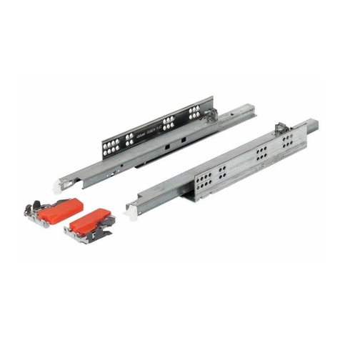
BLUM 21KA000 User manual

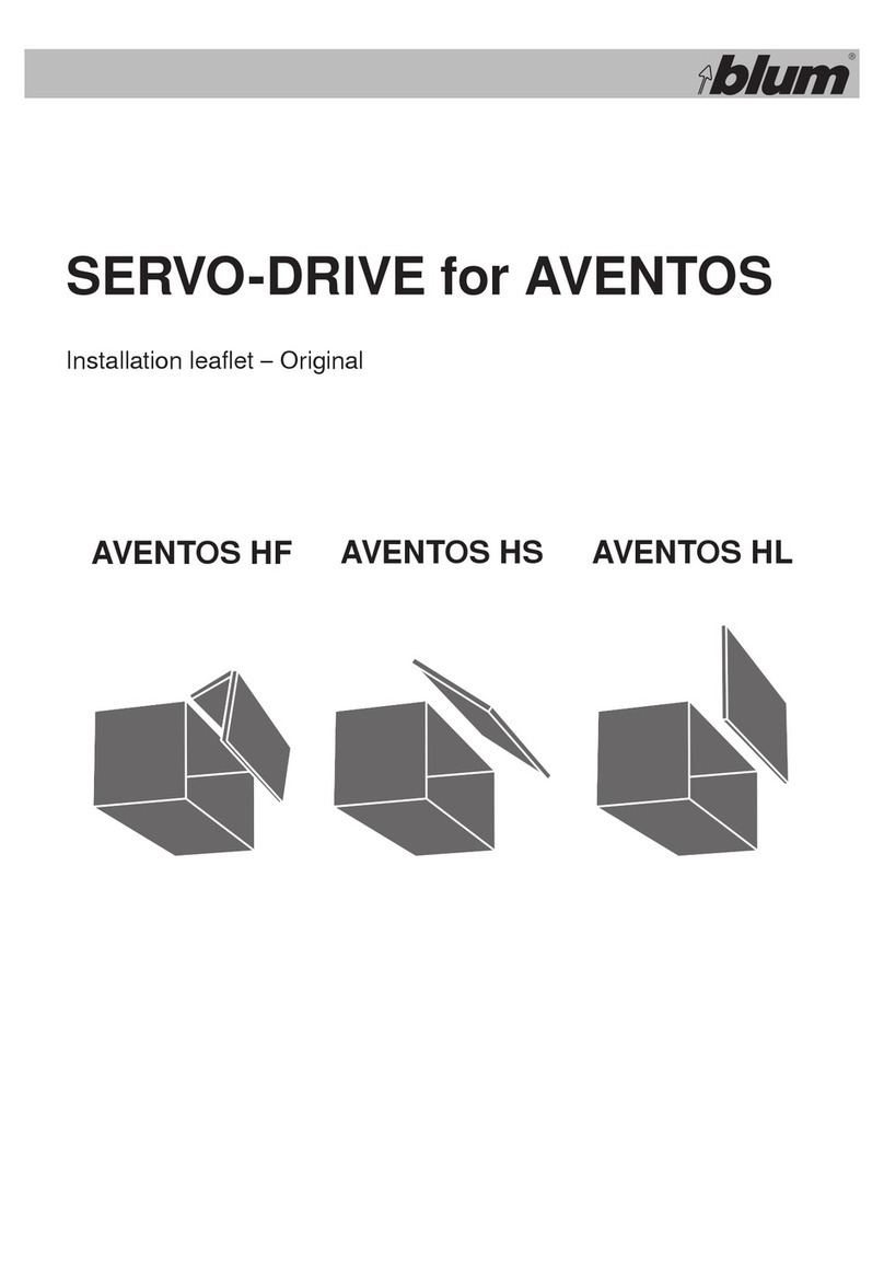
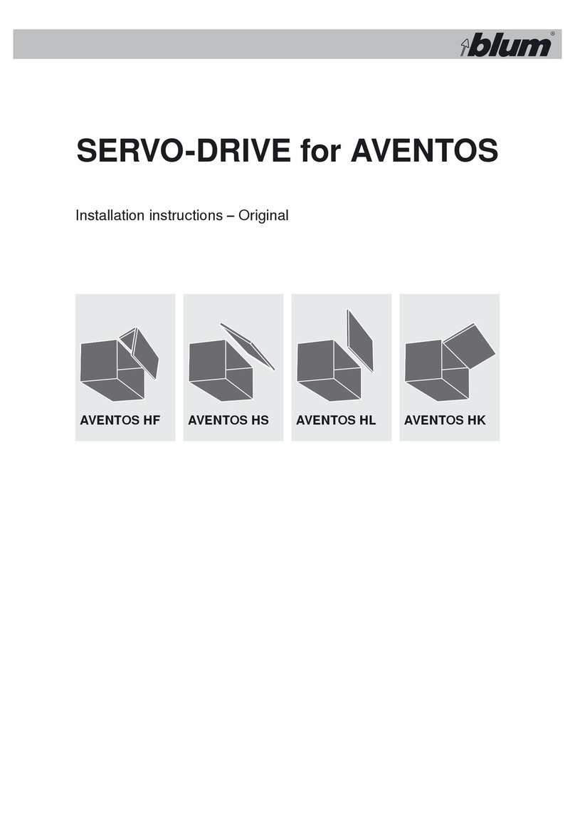
SERVO-DRIVE for AVENTOS
Opens and closes automatically

© 2016 Blum, Inc.
2
Opening and Closing
Lift Systems in an Effortless Way
AVENTOS lift systems open with just a light touch ‒ and then close again with
the press of a button. An inspiring feature that is certain to impress, thanks to
SERVO-DRIVE for AVENTOS, the electrical opening support for lift systems.
2

© 2016 Blum, Inc. 3
Contents
SERVO-DRIVE for AVENTOS
4SERVO-DRIVE Features
6Components for SERVO-DRIVE
8SERVO-DRIVE for AVENTOS HF
10 SERVO-DRIVE for AVENTOS HS
12 SERVO-DRIVE for AVENTOS HL
14 SERVO-DRIVE for AVENTOS HK
16 Electrical Specifications
17 Wiring Options
18 Assembly for AVENTOS HF/HS/HL
20 Assembly for AVENTOS HK
22 Overview of Functions
26 Cover Cap Assembly
26 Battery Replacement
27 Assembly Aids
28 Part Number Index
3

© 2016 Blum, Inc. Subject to technical modifications without notice
4
A light touch on the front using your
hand or elbow is all that's required to
open doors with SERVO-DRIVE
for AVENTOS.
Even large and heavy doors open
effortlessly. For the user, this means
easy access to the cabinet interior.
Comfortable and easy closing
Provided by the easy to reach switch
on the cabinet side.
This enables the doors to close
easily and ergonomically. The proven
BLUMOTION function also ensures
silent and effortless closing.
Features
Effortless Opening and Closing
SERVO-DRIVE for
AVENTOS

Dimensions in millimeters (inch equivalents as noted) © 2016 Blum, Inc. 5
Completely safe – even when closing
Even when the switch has just been pressed for closing – the closing procedure is halted
immediately if the user again reaches into the cabinet and/or an object is placed between the cabinet and the door.
Completely under control
Even though lift systems open and close automatically, the motion can be interrupted at any time.
In addition, lift systems with SERVO-DRIVE for AVENTOS can also be easily opened and closed
manually at anytime, e.g. when there is a power outage.
SERVO-DRIVE
inside
BLUMOTION
inside
Completely synchronized
Up to three drive units can be set for synchronized
motion. Synchronization is ideal for multiple cabinets
that share one wide door.
Collision avoidance
For corner applications, it is especially important that
lift system fronts do not open simultaneously. Thanks
to the “collision avoidance” function, you can set drive
units so that only one front opens at a time.
The Focus is on the User
SERVO-DRIVE for
AVENTOS

© 2016 Blum, Inc. Subject to technical modifications without notice
6
Lift mechanism
Blum distance bumper
Cabling
Power supply and wall mount bracket
Drive unit
SERVO-DRIVE switch
Cover plate
Overview of ComponentsSERVO-DRIVE for
AVENTOS

Dimensions in millimeters (inch equivalents as noted) © 2016 Blum, Inc. 7
Lift mechanism
▀ SERVO-DRIVE-compatible lift mechanism with
tool-free attachment of the drive unit. Please see
AVENTOS brochure (LIT.1000) for more details.
Drive unit
▀ Attaches to the left lift mechanism
▀ Tool-free attachment
▀ Same drive unit used for AVENTOS lift mechanisms
HF, HS and HL
▀ Drive unit with adapter plate for AVENTOS HK lift
mechanism
▀ Additional setting features for synchronization
and collision avoidance
Cover plate
▀ Covers the lift mechanism and drive unit
▀ Extendable to an internal depth of
350 mm to cover the
universal cable
SERVO-DRIVE switch
▀ Attaches to both cabinet sides
▀ Wireless connection to the drive unit
▀ Frequency 2.4 GHz
▀ Certified for use worldwide
Blum distance bumper
▀ Distance bumpers ensure the required trigger path of 2
mm
Cabling
▀ Proven cabling components such as the SERVO-DRIVE
universal cable, cable connectors and cable end
protectors
▀ Easy, practically tool-free cabling
Power supply
▀ Proven SERVO-DRIVE power supply
Wall mount bracket for power supply
▀ For secure mounting
Additional components for AVENTOS HS and HL
▀ Cross stabilizer (new length and configuration)
▀ Modified lever activation
▀ Repositioned screw locations for lift mechanism mounting
After lift mechanism installation and adjustment,
SERVO-DRIVE components are attached to the lift mechanism and cabinet.
Please see the AVENTOS brochure (LIT.AVT1000)
for all other lift system components.
Individual Components SERVO-DRIVE for
AVENTOS

© 2016 Blum, Inc. Subject to technical modifications without notice
8
Ordering InformationSERVO-DRIVE for
AVENTOS HF
NOTE: For additional AVENTOS HF components and installation instructions,
please see AVENTOS brochure (LIT. AVT1000)
SERVO-DRIVE set
Set includes:
▀ Drive unit
▀ 60" universal cable
▀ Cable connector
▀ Cable end protector (qty 2)
Part no.
SERVO-DRIVE set 21FA000
Cover set
Set includes:
▀ SERVO-DRIVE cover plate (left)
▀ Cover plate (right)
▀ Non-handed cover cap (qty 2)
▀ SERVO-DRIVE switches (qty 2)
▀ Ø5 mm Blum distance bumper (qty 6)
▀ Color: gray
Part no.
Cover set 21F8000.NA
A B
Power Supply Set - see page 12
C
A
B
C
B
B
C
B
BC
B

Dimensions in millimeters (inch equivalents as noted) © 2016 Blum, Inc. 9
Ordering Information SERVO-DRIVE for
AVENTOS HS
NOTE: For additional AVENTOS HS components and installation instructions,
please see AVENTOS brochure (LIT. AVT1000)
SERVO-DRIVE set
Set includes:
▀ Drive unit
▀ 60" universal cable
▀ Cable connector
▀ Cable end protector (qty 2)
Part no.
SERVO-DRIVE set 21FA000
Cover set
Set includes:
▀ SERVO-DRIVE cover plate (left)
▀ Cover plate (right)
▀ Non-handed cover cap (qty 2)
▀ SERVO-DRIVE switches (qty 2)
▀ Ø5 mm Blum distance bumper (qty 4)
▀ Color: gray
Part no.
Cover set 21S8000.NA
Arm assembly set
Set includes:
▀ SERVO-DRIVE arm assembly (left)
▀ Standard arm assembly (right)
▀ Stabilizer rod cover cap (qty 2)
Part no.
Arm assembly set 21S3500.01
A B C
NOTE: Stabilizer rod cutting dimension
for SERVO-DRIVE application is length =
interior cabinet width minus 164 (6-7/16")
BB
B
B
B
C
A
D
Power Supply Set - see page 12
D

© 2016 Blum, Inc. Subject to technical modifications without notice
10
Ordering InformationSERVO-DRIVE for
AVENTOS HL
Power Supply Set - see page 12
D
NOTE: For additional AVENTOS HL components and installation instructions,
please see AVENTOS brochure (LIT. AVT1000)
SERVO-DRIVE set
Set includes:
▀ Drive unit
▀ 60" universal cable
▀ Cable connector
▀ Cable end protector (qty 2)
Part no.
SERVO-DRIVE set 21FA000
Cover set
Set includes:
▀ SERVO-DRIVE cover plate (left)
▀ Cover plate (right)
▀ Non-handed cover cap (qty 2)
▀ SERVO-DRIVE switches (qty 2)
▀ Ø5 mm Blum distance bumper (qty 4)
▀ Color: gray
Part no.
Cover set 21L8000.NA
Arm assembly set
Set includes:
▀ SERVO-DRIVE arm assembly (left)
▀ Standard arm assembly (right)
▀ Stabilizer rod cover cap (qty 2)
Cabinet height Part no.
300 to 349 21L3200.01
350 to 399 21L3500.01
400 to 550 21L3800.01
450 to 580 21L3900.01
A B C
NOTE: Stabilizer rod
cutting dimension
for SERVO-DRIVE
application is length =
interior cabinet width
minus 164 (6-7/16")
B
B
A
B
B
C
D

Dimensions in millimeters (inch equivalents as noted) © 2016 Blum, Inc. 11
Ordering Information SERVO-DRIVE for
AVENTOS HK
Power Supply Set - see page 12
C
NOTE: For additional AVENTOS HK components and installation instructions,
please see AVENTOS brochure (LIT. AVT1000)
SERVO-DRIVE set
Set includes:
▀ Drive unit
▀ 60" universal cable
▀ Cable connector
▀ Cable end protector (qty 2)
Part no.
SERVO-DRIVE set 21KA000
Cover set
Set includes:
▀ SERVO-DRIVE cover plate (left)
▀ Cover plate (right)
▀ Non-handed cover cap (qty 2)
▀ SERVO-DRIVE switches (qty 2)
▀ Ø5 mm Blum distance bumper (qty 4)
▀ Color: gray
Part no.
Cover set 21K8000.NA
A B
B
B
B
B
A
C

© 2016 Blum, Inc. Subject to technical modifications without notice
12
SERVO-DRIVE switch
For adding additional activation switches to a SERVO-DRIVE for
AVENTOS application.
▀ Up to six switches can be
added per drive unit
NOTE: A switch can only be synchronized to one drive unit
Part no.
SERVO-DRIVE switch 21P5020
Electrical ComponentsSERVO-DRIVE for
AVENTOS
Power supply set
Set includes:
▀ Power supply
▀ Wall mount bracket
▀ Three-prong power cord
▀ Cable connector
▀ Cable end protector (qty 3)
▀ Cable clips (qty 10)
▀ 19 feet universal cable
▀ Technical information
Power supply set Z10NE02UG10
Part no.
Space requirements and safety distance for power supply
A safety distance of 30 mm must be maintained for air circulation
SERVO-DRIVE power supply components
Supplies power to the drive units
▀ Energy Star Certified
▀ UL certified
▀ Can power up to 16 drive units
▀ Connect to switched GFCI outlet
▀ Cable length is six feet
NOTE: Three-prong power cord required Part no.
Power supply Z10NE020G
Three-prong power cord Z10M200U
Input specifications
Input voltage 100-240 VAC
Input frequency 50-60 Hz
Input current 1.7 A
Inrush current 100 A maximum at 240 VAC
Protection class Class I
Earth leakage current 3.5 mA maximum
Output specifications
Output voltage 24 VDC
Output power max. 72 W
Minimum load None
Load regulation 2%
Ripple and noise 1% peak-to-peak maximum
Over voltage protection At 33 VDC
Overload protection 10.5 A hiccup trip and restart mode with
auto recovery
Short circuit protection Continuous
General specifications
Efficiency ≥ 87%
Switching frequency 65 kHz
No load loss (standby) < 0.5 W
Energy Star Level V
Safety / Approvals
EN / IEL 60950, 60335-1
UL 60950-1, 1310
Environmental information
Operating temperature
32° F‒104° F normal, derate from full
capacity to 75% capacity from 104° F‒140° F
Storage temperature -4° F to 185° F
Protection IP40

Dimensions in millimeters (inch equivalents as noted) © 2016 Blum, Inc. 13
Wiring options
For wall cabinets For SERVO-DRIVE in wall and base cabinets
Wiring Options SERVO-DRIVE for
AVENTOS
Installing cable connector
Insert cable for distribution into open slot
Insert cable for power into open slot
Rotate orange lever to lock into place
Slide cable end protector over exposed cable
NOTE: Ensure piercing pins are not damaged
4
3
1
2
1
2
3
4

© 2016 Blum, Inc. Subject to technical modifications without notice
14
Drive unit preparation
Before SERVO-DRIVE for AVENTOS installation, the lift mechanism
tension adjustment should be made and door operation balanced.
The AVENTOS arm assembly must be in the completely open position
for drive unit installation. Attach the opening angle stop (if required)
only after drive unit installation and before the reference run.
Use the lift mechanism selection switch to select the appropriate
lift system application.
Installation of universal cable
Lift orange universal cable lock lever Insert universal cable (either end of the
cable can be used)
Once cable is inserted, press down on
universal cable lock lever
1 3
1 2 3
2
Installation of SERVO-DRIVE activation switch
NOTE: Use of boring template (M31.2000) recommended, see page 27
The activation switch should be installed by pressing into the cabinet
side with your hand. Do not use hammer to install.
Installation of Blum distance bumpers
For AVENTOS HF – install into drawer front.
Use of six distance bumpers is recommended.
For AVENTOS HS/HL ‒ install into drawer front.
Use of four distance bumpers is recommended.
11
12
30 min.
90 max.
Ø35
*
Assembly for
AVENTOS HF/HS/HL
SERVO-DRIVE for
AVENTOS

Dimensions in millimeters (inch equivalents as noted) © 2016 Blum, Inc. 15
Drive unit installation
Insert the drive unit into back of lift
mechanism and slide forward
Position drive unit into front of lift
mechanism with locator pin
The drive unit can be locked when the orange
slide is no longer visible in the view window.
To lock drive unit to the lift mechanism,
slide the lift mechanism selection switch
to the locked position (reference noted
positions on drive unit). There will be an
audible click when locked.
1
2
3
1
1
2
3
SERVO-DRIVE for
AVENTOS

© 2016 Blum, Inc. Subject to technical modifications without notice
16
Installation of SERVO-DRIVE activation switch
NOTE: Use of boring template (M31.2000) recommended, see page 27
The activation switch should be installed by pressing into the cabinet
side with your hand. Do not use hammer to install.
Installation of Blum distance bumpers
Install into door front. Use of four distance bumpers is recommended.
Two may be sufficient for smaller, lighter doors.
11
12
30 min.
90 max.
Ø35
8
3232
10 min.
*
Assembly for
AVENTOS HK
SERVO-DRIVE for
AVENTOS
Drive unit preparation
Before SERVO-DRIVE for AVENTOS installation, the lift mechanism
tension adjustment should be made and door operation balanced.
Depending on lever arm position, set drive unit accordingly.
Installation of universal cable
Lift orange universal cable lock lever Insert universal cable (either end of the
cable can be used)
Once cable is inserted, press down on
universal cable lock lever
1 2 3
2
1
1 2 3
75°

Dimensions in millimeters (inch equivalents as noted) © 2016 Blum, Inc. 17
Drive unit installation
Position drive unit onto lift mechanism
with locator pin.
To lock drive unit to the lift mechanism,
hold drive unit in place and press down
the three orange lock tabs.
SERVO-DRIVE for
AVENTOS
1
2
1
2

© 2016 Blum, Inc. Subject to technical modifications without notice
18
Deactivation
Additional Features
Activating the SERVO-DRIVE switch
Activating synchronization
Activating collision avoidance
Reset Wireless
Reset Motion
Start reference run
Optional
A
C
D
F
E
B
Function buttons layout
▀ Drive unit
▀ <Reset Motion> button
▀ Motion LED
▀ <SWITCH> button
▀ <SYNC> button
▀ <COLL> button
▀ <Reset Wireless> button
▀ Wireless LED
▀ SERVO-DRIVE switch
1
2
3
4
5
6
7
8
9
Start-Up
1
2 3
4
5
6
7
8
9
Overview of FunctionsSERVO-DRIVE for
AVENTOS

Dimensions in millimeters (inch equivalents as noted) © 2016 Blum, Inc. 19
A Activating the SERVO-DRIVE switch
Setting up the wireless connection between the SERVO-DRIVE
switch and the drive unit. Each switch can only be assigned to one
SERVO-DRIVE unit.
Press and hold the <SWITCH> button
until the LED flashes
Press and hold the SERVO-DRIVE switch
until the LED lights up continuously.
Repeat steps 1 and 2 for additional SERVO-DRIVE switches in the cabinet.
C Activating synchronization
For instructions on activating synchronization, see page 24
D Activating collision avoidance
For instructions on activating collision avoidance, see page 24
B Start reference run
The drive unit recognizes the required parameters using the reference run, setting both upper and lower limits for the motion of the door.
Reference run is required:
LED flashes orange
Close the front manually Press on front: The reference
run starts automatically
Front opens and closes two
times a
utomatically: under no
circumstances
should you try to
manually interrupt or stop the
process
NOTE: If the reference run is interrupted, it should be reset. See reset motion on page 25 then restart reference run.
1 32 4
1 2
Additional Features
Start-Up
Optional
Operation
Lights up continuously
Flashes
Start-Up SERVO-DRIVE for
AVENTOS

© 2016 Blum, Inc. Subject to technical modifications without notice
20
C Activating synchronization
Up to three drive units can be synchronized allowing them to move
simultaneously. This function is required for several cabinets with one
wide front.
Press and hold the <SYNC> button on the 1st drive unit until
the LED flashes
Press and hold <SYNC> on the 2nd drive unit until the LEDs on
both synchronized drive units light up continuously
NOTE: Repeat steps 1 and 2 for all additional drive units
1 2
D Activating collision avoidance
To avoid the collision of door fronts, drive units (six maximum) are
linked so that only one door can be opened at a time. A door front is
prevented from opening as long as a linked door front remains open.
Press and hold the <COLL>
button on the 1st drive unit
until the LED flashes
Close the door manually
Manually open the door of
the unit to be linked
Press and hold <COLL> on
the 2nd drive unit until the
LED lights up continuously
(the same will happen in the
first cabinet)
NOTE: Repeat steps 1 through 4 for all additional cabinets
1 2 3 4
Additional FeaturesSERVO-DRIVE for
AVENTOS
This manual suits for next models
13
Table of contents
Other BLUM Servo Drive manuals