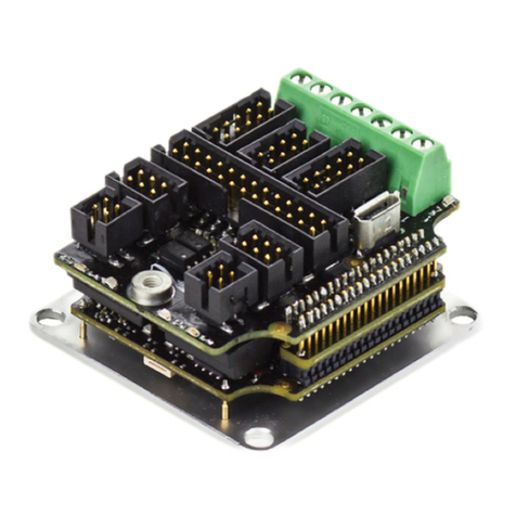
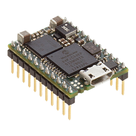
INGENIA Everest XCR User manual

INGENIA-CAT S.L.
AVILA 124
08018 BARCELONA
Everest XCR - Product Manual
Edition 08/04/2019
For the most up to date information visit the online manual.

1. Table of Contents
1. Table of Contents 2
2. General Information 4
2.1. Manual revision history ....................................................................................................................................... 4
2.2. Disclaimers and limitations of liability ............................................................................................................... 4
2.3. Contact ................................................................................................................................................................. 4
3. Safety Information 5
3.1. About this manual................................................................................................................................................ 5
3.2. Warnings............................................................................................................................................................... 5
3.3. Precautions .......................................................................................................................................................... 5
4. Product Description 6
4.1. Part Numbering.................................................................................................................................................... 6
4.2. Specifications....................................................................................................................................................... 7
4.3. Product Revisions .............................................................................................................................................. 12
4.4. Thermal Specifications...................................................................................................................................... 12
5. EtherCAT Specifications 15
6. Installation 16
6.1. Unpacking .......................................................................................................................................................... 16
6.1.1. Back Installation ................................................................................................................................................ 16
6.1.2. Front Installation ............................................................................................................................................... 17
6.1.3. Rework................................................................................................................................................................ 18
7. Connectors Guide 19
7.1. Connector Overview .......................................................................................................................................... 19
7.2. Supply................................................................................................................................................................. 19
7.3. Motor.................................................................................................................................................................. 20
7.4. Feedback Connector.......................................................................................................................................... 20
7.5. EtherCAT Connectors......................................................................................................................................... 24
7.6. Mating Connectors............................................................................................................................................. 25
7.6.1. Mating terminals and cables common for all signal connectors .................................................................... 26
8. Signalling LEDs 29
8.1. Start-up Sequence ............................................................................................................................................. 29
8.2. Driver Status LEDs.............................................................................................................................................. 30
8.3. EtherCAT Status LEDs ........................................................................................................................................ 30
8.4. CANopen Status LEDs ........................................................................................................................................ 30
9. Wiring and Connections 32
9.1. Everest XCR Connection Diagram ..................................................................................................................... 32
9.2. Protective Earth ................................................................................................................................................. 33
9.3. Power Supply and Motor Power........................................................................................................................ 35
9.3.1. Single Power Supply .......................................................................................................................................... 35

9.3.2. Dual Power Supply............................................................................................................................................ 35
9.3.3. Power Supply EMI Filter..................................................................................................................................... 36
9.3.4. Shunt Braking Resistor Connection.................................................................................................................. 36
9.3.5. Motor Connections............................................................................................................................................. 37
3 Phase Brushless .............................................................................................................................................. 37
DC Motor............................................................................................................................................................. 37
Motor Choke ....................................................................................................................................................... 38
9.3.6. Power Wiring Recommendations ..................................................................................................................... 38
Cable Selection .................................................................................................................................................. 38
Soldering Power Pins......................................................................................................................................... 39
9.4. Safe Torque Off (STO), Brake and Motor Temperature.................................................................................... 39
9.4.1. STO bypass (needed when no STO functionality is implemented)................................................................. 42
9.4.2. Motor electromagnetic / electromechanical brake ......................................................................................... 43
9.4.3. External temperature sensor wiring ................................................................................................................. 44
9.5. Feedbacks........................................................................................................................................................... 45
9.5.1. Digital Halls ........................................................................................................................................................ 45
9.5.2. Absolute Encoder 1 ............................................................................................................................................ 47
9.5.3. Absolute Encoder 2 ............................................................................................................................................ 48
9.5.4. Incremental Encoder......................................................................................................................................... 49
9.5.5. Feedback wiring recommendations ................................................................................................................. 51
9.6. Inputs and Outputs............................................................................................................................................ 51
9.6.1. Digital Inputs Interface ......................................................................................................................................52
9.6.2. Analog Input Interface ....................................................................................................................................... 53
9.6.3. Digital Outputs Interface ................................................................................................................................... 54
9.7. Communications................................................................................................................................................ 55
9.7.1. CANopen interface ............................................................................................................................................. 56
CAN wiring recommendations .......................................................................................................................... 57
9.7.2. EtherCAT interface ............................................................................................................................................. 58
Recommended EtherCAT cables and connectors............................................................................................ 59
Ethernet over EtherCAT (EoE) protocol - Used by Motion Lab 3...................................................................... 60
10. Dimensions 62
11. Service 63

Everest XCR - Product Manual|General Information
INGENIA |08/04/2019
4
2. General Information
2.1. Manual revision history
Revision Release Date Changes PDF
v1 01 Apr 2019 Initial version Export as pdf
For the most up to date information use the onlineProduct Manual.
2.2. Disclaimers and limitations of liability
The information contained within this document contains proprietary information belonging toINGENIA-CAT S.L.
Such information is supplied solely for the purpose of assisting users of the product in its installation.
INGENIA-CAT S.L.rejects all liability for errors or omissions in the information or the product or in other
documents mentioned in this document.
The text and graphics included in this document are for the purpose of illustration and reference only. The
specifications on which they are based are subject to change without notice.
This document may contain technical or other types of inaccuracies.The information contained within this
document is subject to change without notice and should not be construed as a commitment byINGENIA-CAT S.L.
INGENIA-CAT S.L.assumes no responsibility for any errors that may appear in this document.
Some countries do not allow the limitation or exclusion of liability for accidental or consequential damages,
meaning that the limits or exclusions stated above may not be valid in some cases.
2.3. Contact
INGENIA-CAT S.L.
120-124 Ávila St.
08018 Barcelona
Spain
Telephone: +34 932 917 682
E-mail:[email protected]
Web site:www.ingeniamc.com

Everest XCR - Product Manual|Safety Information
INGENIA |08/04/2019
5
3. Safety Information
3.1. About this manual
Read carefully this chapter to raise your awareness of potential risks and hazards when working with the Everest
XCR Servo Drive.
To ensure maximum safety in operating the Everest XCR Servo Drive, it is essential to follow the procedures
included in this guide. This information is provided to protect users and their working area when using the Everest
XCR Servo Drive, as well as other hardware that may be connected to it. Please read this chapter carefully before
starting the installation process.
3.2. Warnings
The following statements should be considered to avoid serious injury to those individuals performing the
procedures and/or damage to the equipment:
•To prevent the formation of electric arcs, as well as dangers to personnel and electrical contacts, never
connect/disconnect the Everest XCR Servo Drive while the power supply is on.
• Disconnect the EverestServo Drive from all power sources before proceeding with any possible wiring
change.
•After turning off the power and disconnecting the equipment power source, wait at least 10 seconds before
touching any parts of the controller that are electrically charged or hot.
3.3. Precautions
The following statements should be considered to avoid serious injury to those individuals performing the
procedures and/or damage to the equipment:
• The EverestServo XCR Drive components temperature may exceed 100 ºC during operation.
• Some components become electrically charged during and after operation.
•The power supply connected to this controller should comply with the parameters specified in this
document.
• When connecting the EverestServo XCR Drive to an approvedpower source, do so through a line that is
separate from any possible dangerous voltages, using the necessary insulation in accordance with safety
standards.
•High-performance motion control equipment can move rapidly with very high forces. Unexpected motion
may occur especially during product commissioning. Keep clear of any operational machinery and never
touch them while they are working.
•Do not make any connections to any internal circuitry. Only connections to designated connectors are
allowed.
•All service and maintenance must be performed by qualified personnel.
• Before turning on the EverestServo XCR Drive, check that all safety precautions have been followed, as well
as the installation procedures.

Everest XCR - Product Manual|Product Description
INGENIA |08/04/2019
6
4. Product Description
Everest XCR is a high power, highly-integrated, digital ready-to-go servo drive. The drive features best-in-class
energy efficiency thanks to its state of the art power stage, and can be easily configured with Ingenia's free-to-
download softwareMotionLab 3.
Everest XCR is enabled withEtherCATandCANopencommunications.
Main features:
•Ultra-small footprint
•80 VDC, 30 ARMScontinuous
•Up to 99% efficiency
•Up to 75 kHz current loop, 25 kHz servo loops
•10 kHz ~ 100 kHz PWM frequency
• 16 bit ADC withVGA for current sensing
•Supports Halls, Quadrature encoder, SSI and BiSS-C
•Up to 4 simultaneous feedback sources
•Full voltage, current and temperature protections
•Safety Torque Off (STO SIL3 Ple) inputs
Typical applications:
•Collaborative robot joints
•Robotic exoskeletons
•Wearable robots
•AGVs
• UAVs
•Industrial highly integrated servomotors
•Smart motors
•Battery-powered and e-Mobility
•Low inductance motors
4.1. Part Numbering
Product Ordering part
number
Status Image
Everest XCR
Ready-to-use servo drive featuring EtherCAT
and CANopen communications.
EVE-XCR
For applications requiring a pluggable drive enabled with EtherCAT or CANopen, please seeEverest NET.
For applications not requiring CANopen or EtherCAT, please seeEverest CORE.
PRODUCTION

Everest XCR - Product Manual|Product Description
INGENIA |08/04/2019
7
4.2. Specifications
Part number →EVE-XCR
Electrical and power specifications
Minimum power supply voltage 8 VDC
Maximum absolute power supply
voltage
80 VDC (continuous)
85 VDC (peak 100 ms)
Recommended power supply
voltage
12 VDC ~ 72 VDC
This voltage range ensures a safety margin including power supply tolerances and regulation
during acceleration and braking.
Internal drive DC bus capacitance 30 μF
Logic power supply voltage
(optional)
8 to 50 VDC
Providing the logic supply is optional, as the drive is supplied from the DC bus (single supply) on
its full operating voltage range. When supplied from logic, an intelligent switch will stop
consuming from the DC bus.
Nominal phase continuous current
(RMS)
30 A
Maximum phase peak current
(RMS)
60 A @ 3 sec
Active current limiting based on power stage and motor temperature.
Efficiency Up to 99% @ 20 kHz, 80 V, 30 A
Bus voltage utilisation > 97% @ 20 kHz, 80 V, voltage mode, no load
Motion control specifications
Standby power ≥2.5 W
Lowest standby losses measured with dual supply at 12 V logic, with an active Ethernet
communication, and commutation turned OFF
Supported motor types •Rotary brushless (SVPWM and Trapezoidal)
•Rotary brushed (DC)
Power stage PWM frequency
(configurable)
10 kHz, 20 kHz (default), 50 kHz & 100 kHz
Current sensing 3 phase, shunt based current sensing. 16 bit ADC resolution. Accuracy is
±2% full scale.

Everest XCR - Product Manual|Product Description
INGENIA |08/04/2019
8
Current sense resolution
(configurable)
Current gain is configurable in 4 ranges:
•2.475 mA/count
•1.352 mA/count
•0.570 mA/count
•0.379 mA/count
Current sense ranges
(configurable)
Current ranges for the 4 configurable current gains:
•±81.1 A
•±44.3 A
•±18.7 A
•±12.4 A
Max. Current loop frequency 75 kHz
Max. servo loops frequency
(position & velocity)
25 kHz @ 75 kHz current loop
Feedbacks •Digital Halls (Single ended)
•Quadrature Incremental encoder (RS-422 or Single ended)
•Absolute Encoder (RS-422 or Single ended): up to 2 at the same time,
combining any of the following:
•BiSS-C (up to 2 in daisy chain topology)
•SSI
Supported target sources •Network communication (EtherCAT or CANopen*)
*CANopen is the communication enabled by default. In order to use EtherCAT, the FW must be
updated.
Control modes •Cyclic Synchronous Position
•Cyclic Synchronous Velocity
•Cyclic Synchronous Current
•Profile Position (trapezoidal & s-curves)
•Profile Velocity
•Interpolated Position (P, PT, PVT)
•Homing

Everest XCR - Product Manual|Product Description
INGENIA |08/04/2019
9
Inputs/outputs and protections
General purpose Inputs and
outputs
4 x non-isolated single-ended digital inputs - 5 V logic level & 3.3 V
compatible. Can be configured as:
•General purpose
•Positive or negative homing switch
•Positive or negative limit switch
•Quick stop input
4 x non-isolated single-ended digital outputs - 5 V logic level (continuous
short circuit capable with 470 Ωseries resistance) - 8 mA max. current. Can
be configured as:
•General purpose
•Operation enabled event flag
•External shunt braking resistor driving signal
1 x ±10 V, 16 bit, fully differential analog input for load cells or torque
sensors. Can be read by the Master to close a torque loop.
Shunt braking resistor output Configurable over any of the digital outputs (see above).
Enabling this function would require an external transistor or power driver.
Motor brake output 1 A, 50 V, dedicated brake output. Open drain with re-circulation diode.
Brake enable and disable timing can be configured accurately.
PWM modulation available to reduce brake voltage and power consumption.
Safe Torque OFF inputs 2 x dedicated, isolated (> 4 GΩ, 1 kV) STO inputs (from 3.3 V to 30 V).
The STO inputs include a current limiter at ~ 5 mA to minimize losses.
Motor temperature input 1 x dedicated, 5 V, 12-bit, single-ended analog input for motor
temperature (1.65 kΩpull-up to 5 V included).

Everest XCR - Product Manual|Product Description
INGENIA |08/04/2019
10
Protections •Hardcoded / hardwired Drive protections:
•Automatic current derating on voltage, current and
temperature
•Short-circuit Phase to DC bus
•Short-circuit Phase to Phase
•Short-circuit Phase to GND
•Configurable protections:
•DC bus over-voltage
•DC bus under-voltage
•Drive over-temperature
•Drive under-temperature
•Motor over-temperature (requires external sensor)
•Current overload (I2t). Configurable up to Drive limits
•Voltage mode over-current (with a closed current loop,
protection effectiveness depends on the PID).
•Motion Control protections:
•Halls sequence / combination error (Pending
implementation)
•Limit switches
•Position following error
•Velocity / Position out of limits
Communications for Operation
CANopen (by default) CiA-301, CiA-303, CiA-305, CiA-306 and CiA-402 (4.0) compliant.
125 kbps to 1 Mbps (default).
Note: when configured as CANopen the Ethernet ports can still be used to configure the drive.
EtherCAT (Software selectable) CANopen over EtherCAT (CoE)
File over EtherCAT (FoE)
Ethernet over EtherCAT (EoE)
Note: CANopen is the communication enabled by default. In order to use EtherCAT, the FW must
be updated.
Environmental conditions
Aluminium case Yes (interface board not covered)
Isolation between case and live
circuits
> 200 MΩ. Measured between PE (case) and GND_P and +SUP.
Maximum voltage between PE (case) and live circuits: 440 V continuous,
800 V impulse according to IEC 61800-5-1.
Note: The drive includes 2 nF capacitance between the power supply negative (GND_P) and the
enclosure (PE).

Everest XCR - Product Manual|Product Description
INGENIA |08/04/2019
11
Case temperature Operation:
•-40 ºC to +60 ºC at full current (Minimum power up temperature is -30
ºC)
•+60 ºC to +85 ºC with derated current
For further information, see Thermal Specifications below.
Storage:
-40 ºC to +100 ºC
Maximum humidity 5% ~ 85% non-condensing
ESD and EMC immunity ESD immunity IEC 61000-4-2: ± 30 kV contact discharge , ± 30 kV air
discharge
EFT immunity IEC 61000-4-4: > 40 A
Surge immunity: IEC 61000-4-5 IPPM > 8 A
Mechanical specifications
Dimensions 42.1 mm x 29.1 mm x 23.1 mm
Dimensions include mating connectors
Weight 38 gr
Certifications
Certification CE, RoHS
STO SIL3 (certification pending)
Environmental Specifications IEC 60068-2-1: 2007-03 - Cold (Operational) test
IEC 60068-2-2: 2007-07 - Dry heat (Operational) test
IEC 60068-2-78: 2012-10 - Damp heat, steady state (operational) test
IEC 60068-2-38: 2009-01 - Composite temperature / humidity cyclic
(operational) test

Everest XCR - Product Manual|Product Description
INGENIA |08/04/2019
12
4.3. Product Revisions
Revision Date Notes
1 01 Jun 2018 Initial prototype
2 01 Oct 2018 Second prototype. Known issues or pending features:
•Ethernet physical layer is affected by commutation noise
3 20 Dec 2018 Known issues or pending features:
•Noisy phase current measurement (+/- 150 mA)
•CANopen under development
•Trapezoidal commutation under development
•Halls errors under development
•Efficiency & Bus voltage not yet measured empirically
•STO certification pending
4 14 Apr 2019 First official product release.
5 24 Mar 2019 • Added CANopen variant
•Added trapezoidal commutation
•Improved current sensing measurement
6 24 May 2019 •Improvements related to industrialization
4.4. Thermal Specifications
The following diagram depicts the general dissipation model and the equivalent thermal model.

Everest XCR - Product Manual|Product Description
INGENIA |08/04/2019
13
Following figure show the maximum phase current at different Everest Case temperature. For highestcurrentat a
given temperature, low PWM frequency is preferred. The 10 kHz frequency will reduce power losses but may not be
suitable for low inductance motors or acoustic noise sensitive
Notice that current is expressed in RMS.To obtain the equivalent current in amplitude just multiply it by√2.
To ensure a proper performance of Everest XCR, thecase temperature must be held always below 85 ºC (Tc-
max=85 ºC)
Following figure show the theoreticalPower Losses at different operating points.

Everest XCR - Product Manual|Product Description
INGENIA |08/04/2019
14
Please, use the following procedure to determine the required heatsink:
1. Based on the voltage & continuous current required by your application and Currentderating graph
determine the Case temperature Tc. Remember that Case temperature must be always below 85 ºC (Tc< 85
ºC)
a. For example: If the application requires 30 A@ 80 V (20 kHz) the Tcwill be 72.5 ºC
2. Based on the voltage & continuous current required by your application and Power losses graph determine
the generated Power LossesPLto be dissipated.
a. For example: If the application requires 30 A@ 80 V (20 kHz) the PLwill be 28.5 W
3. Determine the Thermal impedance of the used thermal sheetRth(c-h)
a. For example, a thermal sheetTGX-150-150-0.5-0,which has an estimated thermal impedance ofRth(c-
h)=0.2 K/W
4. Based on the ambient temperature and using the following formula determine the maximum thermal
impedance to air of the required heatsink Rth(h-a)
a. For example: If the application requires 30 A@ 80 V(20 kHz)working at Ta= 25 ºC and we use a
thermal sheet with Rth(c-h)=0.2 K/W the required thermal impedance of the heatsink will be Rth(h-a)=
1.87 K/W

Everest XCR - Product Manual|EtherCAT Specifications
INGENIA |08/04/2019
15
5. EtherCAT Specifications
Ports available 2
LED Signals Status LED
Link/Act LED
Supported Mailbox CoE, FoE, EoE
SDO info
Supported
Segmented SDO
Supported
SDO complete access
Supported
Modes of Operation DS402 drive device profile
Voltage mode
Current mode
Cyclic Synchronous Current Mode
•
Max. Update rate up to 100
μ
s (10 kHz)
Current amplifies mode
Profile Velocity
Profile Position
Homing modes
Interpolated Position Mode
Cyclic Synchronous Position Mode
•
Max. Update rate up to 100
μ
s (10 kHz)
Cyclic Synchronous Velocity Mode
•
Max. Update rate up to 100
μ
s (10 kHz)
Synchronization modes SM synchronous
Distributed clock
Process data object Configurable
Up to 20 bytes in each direction

Everest XCR - Product Manual|Installation
INGENIA |08/04/2019
16
6. Installation
6.1. Unpacking
When unpacking the Everest XCR please ensure the following:
•Remove the drive from the bag carefully.
•Check that there is no visible physical damage. If any, report it immediately to the carrier.
• Check the part number of the drive on the side label.
Mounting the Everest to a Heatsink or Cooling Plate
The Everest XCR has 4x M2.5 threaded holesfor assembling the drive to a cooling plate or heatsink. The maximum
threaded length is 6.4 mm. Assembling the Everest correctly is essential to:
1. Provide a conduction heat dissipation path.
2. Ensure electrical conduction between the drive and Protective Earth, chassis or the motor enclosure. This is
strongly recommended for EMC.
3. Secure the drive in place to prevent any damage.
6.1.1. Back Installation
The preferred way to assemble the Everest XCR is from the back using a thermal interface tape (Suggested part
numbers are T-Global Technology LI98-1140-27-0.25, for best assembly strength and tolerant to minor surface
imperfections,LI98-1100-27-0.15 for high quality flat rectified surfaces or Berquist Bond-Ply 100 series) and 4 x M2.5
screws. Follow this steps:
1. Ensure the bottom surface of the Everest and the heatsink are clean and dry. Isopropyl alcohol (isopropanol)
applied with a lint-free wipe or swab should be adequate for removing surface contamination such as dust
or finger prints. Do not use “denatured alcohol” or glass cleaners which often contain oily components.
Allow the surface to dry for some minutes before applying the tape. More aggressive solvents (such as
acetone, methyl ethyl ketone (MEK) or toluene) may be required to remove heavier contamination (grease,
machine oils, solder flux, etc.) but should be followed by a final isopropanol wipe as described above. Note:-
Be sure to read and follow the manufacturers’ precautions and directions when using primers and solvents.
2. Cut a 34 mm x 27 mm piece of the thermal tape.
3. Apply the tape to the Everest bottom at a modest angle with the use of a squeegee, rubber roller or finger
pressure to help reduce the potential for air entrapment under the tape during its application. The liner can
be removed after positioning the tape onto the first substrate.
4. Assemble the Everest to the heatsink ensuring alignment to the holes by applying compression to ensure a
good wetting of the substrate surfaces with the tape. Proper application of pressure ~ 5 kg and time (> 5 s) is
crucial for best thermal performance as the surface adhesive will have better wetting. A twisting motion
during assembly will improve wetting.This should be a back and forth twisting motion during the
application of compression. Moderate heat (<85ºC) can be employed to increase wetting percentage and
wetting rate of the substrates and to build room temperature bond strength.
5. Screw the 4 x M2.5 screws applying between 0.17 and 0.3 Nm of torque. Note that the M2.5 thread should be
handled gently. The threads may penetrate the thermal interface material if the corners have not been
trimmed.
Note, for highest heat dissipation performance (high current and voltage application) thermal grease or silicone
may also be used. However it complicates and makes a dirtier process.

Everest XCR - Product Manual|Installation
INGENIA |08/04/2019
17
6.1.2. Front Installation
Front installation can be done using the Flat heatsink that is supplied with the thermal tape and 4 x M2.5 x 8 DIN965
screws (PN EVE-FHS). .
1. Assemble the Everest-XCR to the flat heatsink following the Back Installation process.
2. Use appropriate thermal interface material between the previously cleaned Flat Heatsink and the other
surface. 3M8805, t-Global Technology LI98, thermal grease, can be used.
3. Screw using M3 screws with appropriate torque according to the base material.

Everest XCR - Product Manual|Installation
INGENIA |08/04/2019
18
6.1.3. Rework
Rework that requires removing the Everest from the plate should be done carefully:
1. Remove the 4 M2.5 screws.
2. Separe the Everest from the heatsink by prying, torquing or peeling. Make sure the forces are applied to the
Everest enclosure and not to the PCB or connectors.
3. The thermal tape will be destroyed upon separation and must be replaced. The surfaces should be re-
cleaned according to the recommendations mentioned above. Do not try to reuse the thermal tape.
4. Heating the substrates can reduce the adhesion level and make removal easier

Everest XCR - Product Manual|Connectors Guide
INGENIA |08/04/2019
19
7. Connectors Guide
7.1. Connector Overview
7.2. Supply
P1 connector
2.6 mm diameter gold plated solder pads or flying leads option. Pad pitch is 5.08 mm.
Pin Signal Function
1 POW_SUP Power supply positive
2 GND_P Power supply return

Everest XCR - Product Manual|Connectors Guide
INGENIA |08/04/2019
20
Notes
Recommended section wire is 2.5 mm2~ 5.3 mm2, AWG 10 ~ AWG 13 for applications working at maximum
current. Adapt the cable diameter to your current needs.
It is recommended to use flexible silicone cables to ensure low mechanical stress to the board as well as high
temperature ratings (≥110 ºC). Diameter of the cable Jacket (insulator) should be less than 5.08 mm to prevent
collision between wires.
When using power supply only (no logic supply) always connect pins 27 (+LOG_SUP) and 29 (GND_D) of I/O
connector J2 together.
7.3. Motor
P2 connector
2.6 mm diameter gold plated solder pads or flying leads option. Pad pitch is 5.08 mm.
Pin Signal Function
1 PH_A Motor phase A
2 PH_B Motor phase B
3 PH_C Motor phase C
4 PE Protective earth connection, internally connected to standoffs and drive housing.
Notes
Recommended section wire is 2.5 mm2~ 5.3 mm2, AWG 10 ~ AWG 13.
For long cables it is essential to use a shielding connected to protective earth at both ends of the cable.
7.4. Feedback Connector
Other manuals for Everest XCR
2
Table of contents
Other INGENIA Servo Drive manuals

INGENIA
INGENIA Everest CORE User manual

INGENIA
INGENIA Jupiter JUP-20/80 User manual

INGENIA
INGENIA Earth EAR-3/40-C-P User manual

INGENIA
INGENIA Everest XCR User manual

INGENIA
INGENIA Neptune User manual

INGENIA
INGENIA Triton Core User manual

INGENIA
INGENIA Titan GO User manual

INGENIA
INGENIA Nix series User manual

INGENIA
INGENIA Triton Go User manual

INGENIA
INGENIA Titan GO User manual