Hasselblad 2000FC User manual

HASSfLBTAD-
Instruction
manual

Hasselblad
2000FC
The Hasselblad 2000F(. . 2 1/4x2 1/4 single-lensrellex camera leaturing lens,
magazine,viewlinde tring screeninterchangeability. Its unique design
givesyou a choice of shuttet tptioits, focal plane or leaf
, depending on your .
requirements.
The'2000' in the designation2000FCstands
for the fastestshutter speed,
1/2000
s,
the'F' st,."',vlr
f
ot focal planeshutter and the'C' stands
for the (Synchro-)
Compur leaf shuttf'r'.
.\, Jtou
canwork with the camera'Sown f
ocalplaneshutter
or with theleaf qr,i,'r. ouilt into lensesmade
for theHasselblad
500C, 500C/IuI,
5008L and 1(tt , rittlsince1957.
Lenses
espet
i::'; ."'.signed
for the Hasselblad
2000FCwill bereferred to as
F
lensesin tlt.'l :, ,i.ructionmanual. Lenses with Synchro-Compur leaf shutters will
beref
erred r" .*C lenses
F lenses,v',tich have no built-in shutter, can only be used with the camera's focal
plane shutter.But when a C lensis attached to the Hasselblad 2000FC, you can
either usethe canrera's
focal plane shutter or the leaf shutter in the lens.
The focal plane shutter serves
asa blind when the leaf shutter is the shutter of
choice. The leaf shutter provides the advantageof flash synchronization at all
shutter speeds
dowtt to 1/500 s.
The Hasselblad 2000FC ha"qan electronically timed focal plane shutter with
X synchronization at I/90 s.r'4rt
slower.Electronic shutter timing makesfor
extremely accurateshutte- ation.
A choice of mirror *
rapher cansel-'
the mirror re
The mirr
The pro
also
beei
This mc
the car
Itisc
mQn:
you
mother feature of the Hasselblad2000FC. The photog-
tu producing instant mirror return or a program in which
te i"'' "no,sition
until the film isadvanced
after exposure.
rraised
position f
or specialpurposeapplications.
,rnntional multiple exposureson the same frame has
theHasselblad
2000FC.
erooperation and describesomeof the waysto utilize
id features.
'ircroughly study a new or unfamiliar camera's instruction
eraisput to use.The f
ew minutes spentthis way can save
uthle later on.

2000FC
21
2t_)
1.
2.
t
J.
4.
5.
6.
7.
8.
9.
10.
11.
12.
13.
t4.
15.
16.
17.
18.
19.
20.
2t.
22.
23.
24.
25.
Magazine release
catch
Folding crank for film advance
and shutter cocking
Magazine designation
Film indicator
Film winding crank
Film plane marking
Frame counter window
Film advanceindicator window
Shutter cocking indicator window
Strap lug
Pre-releaselatch
Mirror program settings
Mirror program disc
Shutter release
button
Cable release
socket
External bayonet accessory
mount
Internal bayonet accessorymount
Exposure value scale
Exposure value index (red)
Button for cross-couplingof
shutter and diaphragm
Focusing ring
Distance scale
Depth-of-field scale
Aperture ring with aperture scale
Shutter speed
ring with shutter
speedscale
Fig. 1

26.
27.
28.
29.
30.
31.
JJ.
34.
35.
36.
37.
38.
39.
Catch for focusing hood
and fine-focus magnifier
Fine-focus magnifier
Focusinghood
Index for shutter speeds
Index for aperture scale
Index for distancescale
Synchronization terminal for
focal plane shutter
Shutter speed
prong
Depth-of-field preview catch
Fixed grip ring
Projecting aperture
grip
Lens lock release
button
Lever for locking shutter speedring
Battery compartment with
batterycassette
40. Tripod plate and 3/s/'
tripod socket
41. Accessory
rail
42. Straplug
43. Magazine support catches
44. Roll holder key
45. Film consumption indicator
46. Magazine slide
47. Focusing
screen
2(XX)FC] lens
Fis..2

Open the focus'ing hood (28) by sliding
the catch (26) to the right.
The magazine slide (46) must be removed
prior to exposure. A nrumber should show
in the fra'me counter window (7), and the
indicator wrindows (8 and 9) should dis-
play white signals.
Button (20) for cross-coupling of shutter
and diaphr'agm.
Folding crank (2) which is wound one
full turn to advance the film and cock the
shutter.
Mirror program disc (13). To be pressed
at the start of shutter cocking with the
crank (2) when intentional double expo-
sures are desired. Rotate the disc with a
coin to select a mirror action program.
Pre-releaseop'eration using the latch (11)
outs camera reaction time 'to a minimum.
Only actu,al ,shutter release then takes
place when the camera is triggered.
The camera is released when the release
latch (14) is pressed.The button conta'ins
a cablerelease
socket.
,4
CAMERA OPERATION IN BRIEF The fine-focus magnrifier (27) pops up
when the catch (26) on an open focusing
hood is again slid to the right.
The focusing hood (28) can be removed.
Just slide it back off the camera body
after first r,emoving the film magazine.
The focusing screen (47) is also inter-
changeaDle.
Aperture, shutter speed and distance are
set against the indexes (29, 30, 31).
Focusby rotating the focusing
ring (21).
Synchronization terminal (32). X syn-
chronization
at I/90 sor longer.
Acces,soryrail (4I) for e.g. a sports view-
finder, spirit level or adjustable flash shoe.
The depth-of-field preview catch (34) can
be locked in the stopp,eddown position.
Lever (38) for locking the shutter speed
ring.
Battery cassette
for 6 V battery.
ii
L
The lens can
lock release
hould never
be remoVed
once the lens
button (37) is pressed
. It
be removed
unless
the cam-
I
*
era is cocked.
Bayonet acc,essory
mounts for supplemen-
tary lenses,filters and lensshades.
Tripod plate (40) with 3/e'tripod socket.
Fie. 3

Shutter
Shutter
settings
Shutter
speeds
Flash
synchronization
Focal plane
Speeds:
B, t-I12000 s
set
onthecamerats
shutter
speed
ring (25).
The flash contact is
connected to the camera's
flash terminal (32).
Shutter speeds
of 1/90 s
or longer seton tl '
camerats shutter ,d
ring (25).
F lens plus focal
plane shutter C lens plus focal
plane shutter
Focal plane
C lens plus leaf
shutter
Leaf shutter
Leaf shutter setat B.
Leaf shutter's syncltro-
nization selector sot at X.
Camera's shutter speed
ring locked in position C.
Speeds:
8,1.-112000
s
set
onthecamera'sshutter
speedring (25).
Speeds:
B, L-11500 sset
on theshutterspeedring
of thelens.
The flash contact is con-
nected to the flash terminal
of the lens.
Optional shutter speed
ranging from B, 1-L1500 s
set on the shutter speed
ring of the lens.
The flash contact is con-
nected to the camera's
flash terminal (32).
Shutter speeds
of l-l90 s
or longer set on the
camera's shutter speed
ring (25).

Left-hand grip
Fig. 5 shows the best way to hold a Has-
selblad 2000FC when photographing.
Cradle the camera in your left hand with
your left index finger resting lightly on
the release
button.
This leaves
your right hand free for other
operations such as film winding, shutter
cocking, focusing etc. Make it a habit to
use the left-hand grip when holding your
camera.
Focusing hood (Fig. 6 and 7)
The focusing hood (28) opens automat-
ically when the catch (26) ,is slid to the
right. The hood's fine-focus magnifier is'
usedfor critical focusing. It pops up when
the catch (26) is again slid to the right
with the hood open. To close the hood,
first flip the magnifier down until it clicks
into place. Then fold the hood walls down
over the focusing screen, side walls first,
followed by the rear wall and finally the
lid.
Changing viewfinders
1. Remove the film magazine.
2. Slide
the finder back out of the
grooves
(only slight resistance should be felt).
3. Slide another finder forward into the
grooves.
4. Reattach a film magazine.
Fig.5
eh

Fig.6
Fig.7
LENSES
Introduction
All the lenses made for the Hasselblad
500C, 500C/M, 500EL and 500ELM
(C lenses in which the C stands for the
built-in Synchro-Compur leaf shutters)
also fit the Hasselblad 2000FC. Howev,er,
a series of lenses (F lenses) have been
especiallydesignedfor the 2000FC.
F lenses
(F'ig.8)
Lenses for the Hasselblad 2000FC will be
referred to as F lensesin this instruction
manual (the 'F' standsfor the focal plane
shutter, but will not be found on the
lensesthemselves).Since
F lenseshave no
built-in shutters, they can not be used
with the Hasselblad 500C, 500C/M.
500EL or 500EL/M.
F lenseshave diaphragms which automat-
ically stop down to the preselected f/stop
when the camera is triggered and reopen
to the maximum aperture after concluded
exposure. However, the depth-of-field
yielded by the preselected f/ stop can be
previewed using the depth-of-field preview
catch (34).
C lenses
(Fig. 9)
Lenses made for the Hasselblad 500C,
500C/M, 500EL and 500EL/M will be
referred to as C lensesin this instruction
manual. (However, this designation will
not be found on the lenses themselves).
C lensescan even be used with the Has-
selblad 2000FC.
Parographs printed in bold face indicate
the useof C-len"o
Fig. 8
Fig. 9

Fig.10 Fig.11
The C lenses have diaphragm which auto-
matically stop down to the preselected
f/stop when the camera is triggered. They
also have built-in Synchro-Compur leaf
shutters fully synchronized at all shutter
speeds
(f-1l500 s).
The shutter is cocked and the diaphragm
reopens to its maximum aperture during
the film advancesequence.
CHANGING LENSES
F lenses
Lens removal (Fig. lO)
Make sure the shutter is cocked (white
signal in the shutter cocking indicator
window 9).
Hold the lens by the fixed grip ring (35)
but never press
on the button f
or cross-cou-
plins of shutter and diaphragm (20) during
lens removal because this could ceuse
damage to the cross-coupling mechanism.
Press the lens lock release button (37\
with your left index finger. Then remove
the lens by turning it counter-clockwise
one-fifth of a revolution using gentle
pressure
only.
Note: If the lens refuses to budge, the
camera is in the pre-release
mode. Restore
it to the normal mode by depressingthe
slotted mirror program disc (13) and
rotating the film advance crank (2) a full
turn.
Lensattachment (Fig. 11)
Make sure the shutter is cocked and not
in the pre-release
mode (see
p. 21). Other-
wise the lens mechanisur could be dam- Fig. 12

agedwhen the lens is attached. Also make
surethe diaphragm is cocked. The slot (A)
on the head of the cocking shaft should
point to the red dot (B). (Also see 'Dia-
phragm cocking' for details on the cock-
ing of releasedlenses.)
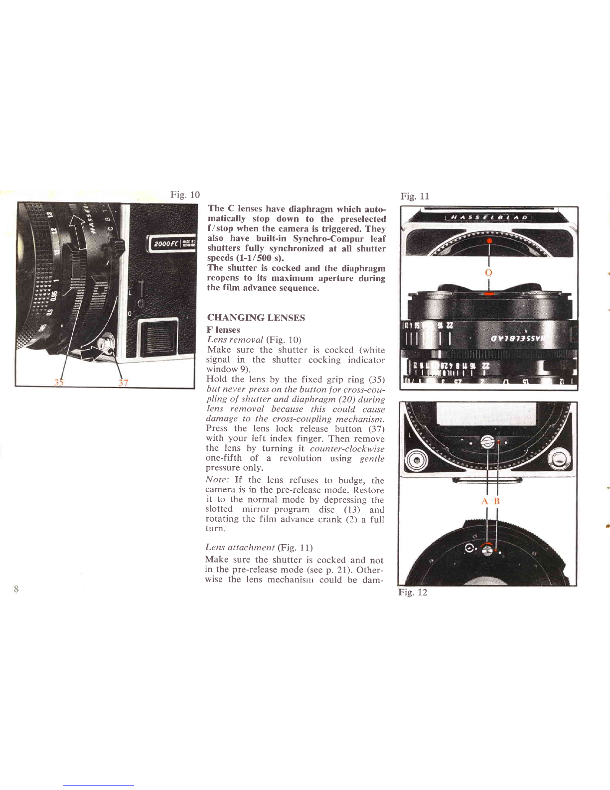
Align the red triangle at the rear of the
lens with the red dot (O) on the camera
lensmount (Fig. 11).Then carefully insert
the lens into the camera lens mount and
rotate the lens clockwise one-fifth of
furn-using gentle pressure-until the
lenslocks in place with an audible click.
Never press on the button for cross cou-
pling of shutter and diaphragm (20) while
changing lenses, since this could cause
damage to the cross-coupling mechanism.
C lenses
C lensesare attached and removed in the
samemanner as F lenses.
Diaphragm cocking (Fig. 12)
F lenses
When an F lens is attached to the camera,
the diaphragm mechanism in the lens is
automatically cocked at the same time as
the film is advanced with the folding
crank (2).
Make sure the diaphragm is cocked before
a lens is attached to the camera. The dia-
phragm is cocked when the slot (A) on
the head of the cocking shaft points to
the red dot (B). If the lens has been off
the camera and the diaphragm inad-
vertently released the diaphragm must be
recocked before the lens can be reattached
to the camera.
The diaphragm is cocked by rotating the
cocking shaft clockwise, using e.g. a coin
of suitable size in the shaft slot (A), slight-
ly less than one full turn until the shaft
stops in the cocked position. (This proce-
dure should be carried out with great
caution so that the coin or any other
device used to cock the shaft does not
skip out of the slot and damages the rear
lens element.)
Note: The same cocking procedure is also
employed for extension tubes.
C lenses
The shutter and diaphragm of C lensesare
cocked in the same manner as in F lenses.
BATTERY (Fig. L3)
The electronics responsible for shutter
timing are powered by a 6 V baittery (e.9.
PX-28).
Batteries marked with a lower voltage
must not be used.
Loading or replacing battery
- Pull out the battery oassette.
- Insert the battery with the (* ) terminal
facing the (+ ) marking in the cassette.
- To avoid inserting a battery rin a me-
chanically trriggeredcam,ex&,depressthe
slotted mirror program disc (
13) and
rotate the film advance crank (2) a full
turn.
(If a battery is inserted in a mechan-
i,cally triggered camera, the I'ife of the
battery will be dnastically reduced.)
- Reinsert the cassette containing the
battery in the cftmera.
A fre'sh battery of the above type should
last for at least 20,000 exposures. Check
regularly to ensure that the battery is
not leaking. To prevent the leakage
which sometimes occurs after protracted
storage, change the battery at least once
a year.

Fig.
16
Fig. 14 FILM MAGAZINES
All the film magazines in the Hasselblad
system fit the Hasselblad 2000FC except
the Magazine 80 for Polaroid film whose
pro
jecting glass plate will destroy the
shutter curtains in the camera.
Changing magazines
(Fig. 15)
Make sure the indicator windows (8 and
9) display white signals before a magazine
is switched.
The magazine slide (46) must be inserted
before the magazine can be removed from
the camera.
Slide the magazine release
catch (1) to the
right, swing down the magazine and lift it
off the camera's two support catches (43).
The magazine slide (46) protects the film
from fogging when the magazine is off the
camera.
A magazine is attached to the camera as
follows:
Hook the magazine securely onto the two
magazine support catches (43) and pivot
the magazine up against the upper locking
latches (A) while simultaneously sliding
the magazine release
catch (1) to theright.
Release the release catch. Then slide it
back to the left for secure locking.
Pull out the magazine slide" Your first
exposurecan now be made.
Note: A magazine can only be removed
from the camera when the magazine slide
is in place. No exposure can be made
when the slide is in an attached magaTine.
Fie. 17
Fig.15

Fig.18
fndicator signa,ls
(Fig. 16 and 17)
The camera body and film magazine have
indicator windows (8 and 9) whose dis-
plays are affected by the film advance.
The following signalscan be displayed in
the indicator windows:
A. Both windows white: Camera ready for
exposure.
B. Both windows red: An exposure has
been made but the film has not been
advanced nor the shutter cocked. Ad-
vance the film and cock the shutter with
the crank (2).
C. Film advance indicator window (8) red
and shutter cocking indicator window (9)
white: Magazine attached to a cocked
camera with the exposed frame un-ad-
vanced. Remove the magazine,trigger the
camera, replace the magazine and ad-
vancethe film.
D. Film advance indicator window (8)
white and shutter cocking indicator
window (9) red: Magazine with advanced
film attached to uncocked camera. De-
press the mirror program disc (13), in-
cluding the red center button, and wind
the crank (2) one full turn. The disc (13)
only has to be kept depressedduring the
initial phase of crank revolution.
General rule: Make sure the signalsin the
indicator windows (8 and 9) display the
seme color before attaching a magazine.
Miscellaneous
The film winding crank (5) is only blocked
at frame 1. So you can wind film onto
the magazine take-up spool any time after
frame 1is exposed.
The frame counter (7) is automatically
reset when the roll holder key (.4+1
is
removed.
The center of the ro11holder key (44)
features a film consumption indicator (45)
which is white when the film supply spool
is full but which gradually turns red as
each frame is advanced. A completely red
film consumption indicator means that
the final frame on a roll has been exposed
or that there is no film in the magazine.
The ASA or DIN film speed (B) can be
seton the film indicator (4).
Settings are made by flipping down the
indicator lid (4) and rotating the serrated
ring. There is space behind the lid (4)
for insertion of a film box tab as a
reminder.
Fis.19

Fig. 20 Fig.27 Fig.22
$
I
I
I
Fis.24 Fis.25
Fig.23

I
Loading of Magazine A12
Fig. 20. Fold out the magazine's
roll hold-
er key.
Fig.2l. Turn theroll holder key counter-
clockwise. Pull the roll holder out of the
magazlne.
Fig. 22. Flip up both spool clips. In-
sert an empty take-up spool onto the
prong on the take-up side and flip down
the take-up clip (with the knurled knob)
onto the spool.
Fig. 23. Insert a roll of film onto the
prong on the film side as shown in the
photograph and flip down the film clip
(with the red arrow) onto the film spool.
Make sure the entire paper band around
the film is removed first.
Fig. 24. Turn the roll film holder clock-
wise so that the film clamp (A, Fig. 25)
opens.
Fig 25. Pull out 3-4 inches of paper
backing and guide the backing under the
film clamp (A). Turn the roll holder key
counter-clockwise so that the paper back-
ing is held down by the film clamp (A).
Fig. 26. Insert the tongue of the paper
backing into a take-up spool slit.
Fig. 27. Roll the paper backing onto the
take-up spool, turning the clip knob clock-
wise, until the arrow on the paper backing
is aligned with the arrow on the film clip.
Fig. 28. Carefully reinsert the roll holder
into the magazine and lock it in place by
turning the roll holder key (44) clockwise.
Fie. 29. Make sure the magazine slide (46)
Fig.26 Fig.27
Other manuals for 2000FC
2
Other Hasselblad Film Camera manuals

Hasselblad
Hasselblad XPAN II User manual

Hasselblad
Hasselblad Xpan User manual

Hasselblad
Hasselblad 202FA User manual

Hasselblad
Hasselblad 501CM User manual

Hasselblad
Hasselblad XPAN II User manual

Hasselblad
Hasselblad 503CW User manual

Hasselblad
Hasselblad 905SWC User manual

Hasselblad
Hasselblad D 1600 F User manual

Hasselblad
Hasselblad 501CM User manual

Hasselblad
Hasselblad XPAN II User manual