Introduction to the Hasselblad Camera System
As a Hasselblad owner you have in your possession
a camera of exceptional quality the product of an in-
ternationally renowned tradition of excellence in the
world of photography. Victor Hasselblad, the father
of the cameras which bear his name, was himself an
accomplished photographer. It was to satisfy his own
exacting standards and diverse requirements that he
rst envisioned the Hasselblad system: a medium
formatsinglelensreexcamerawithinterchangeable
lenses and lm magazines A photographer rst and
businessman second, Victor Hasselblad would never
sacrice quality for ease of production. To this day,
Hasselblad cameras are painstakingly crafted with this
principle in mind.
The Hasselblad system has been taken to the ends of
the earth and beyond - into space, to earn its reputa-
tionforreliabilityandabsolutedelity.Arangeofac-
cessoriesaordslimitlessexibilityand the potential
for paramount photography in any application. The re-
alization of this potential is of course dependent upon
theskill,careandjudgmentofthephotographer.
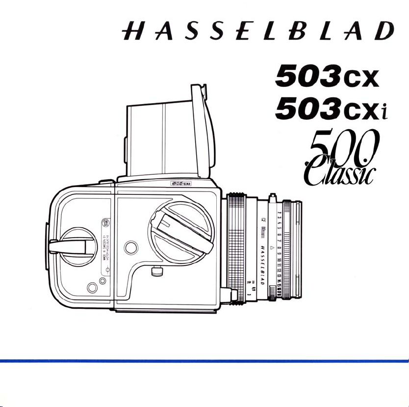
The Hasselblad 503CX, 503CXi and 500 Classic are
medium format single lens reex cameras featuring
lens,magazine,viewnderandfocusingscreeninter-
changeability. The 503CX is an upgraded version of
the500Classicwith‘TTL’(throughthelens)‘OTF’(O
The Film) ash metering and a number of additional
renements.The503CXiisafurtherrenementofthe
503CX. The Hasselblad 500 Classic is a 500C/M cam-
era body with a micro raster /line grid focusing screen
complete with the Planar CF 2,8/80 mm lens and the
A12lmmagazine
This instruction manual describes in detail how to op-
erate these cameras Where the operation of the cam-
eras is the same a single set of instructions common
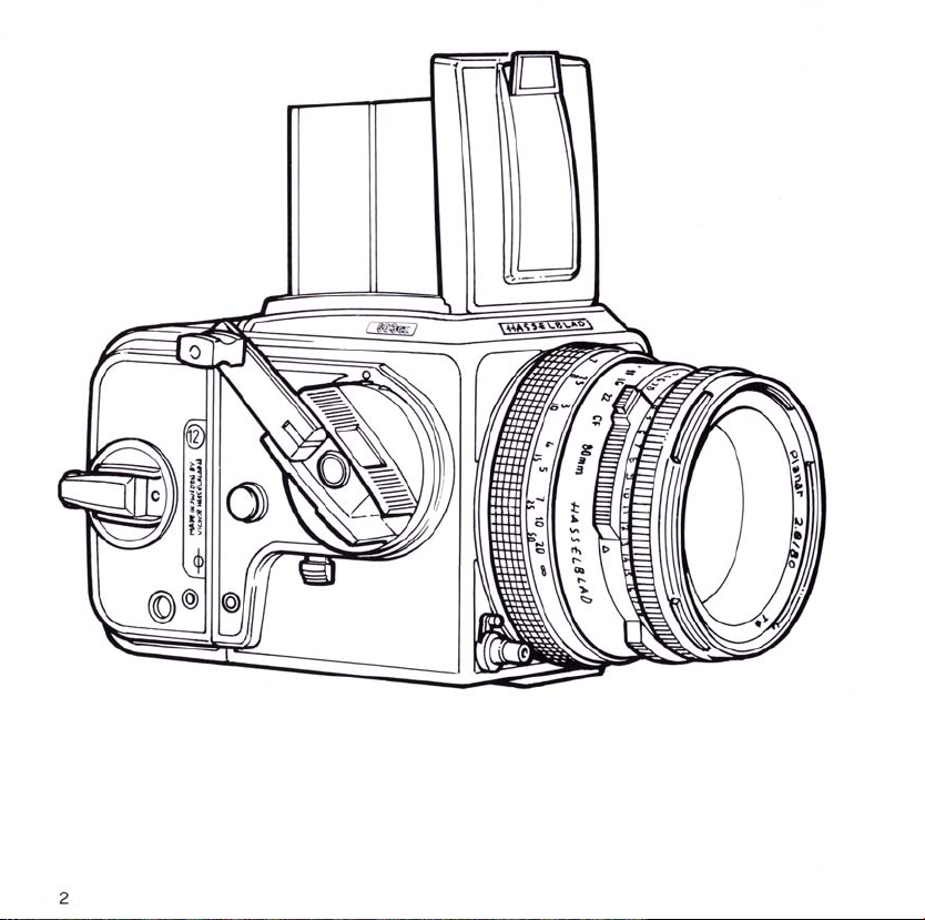
to both models is presented The illustrations accom-
panying the common instructions show the 503CX but
apply equally to the 503CXi and 500 Classic. Where
there are operating dierences between the 503CX,
503CXi and the 500 C/M, these are documented sep-
arately.
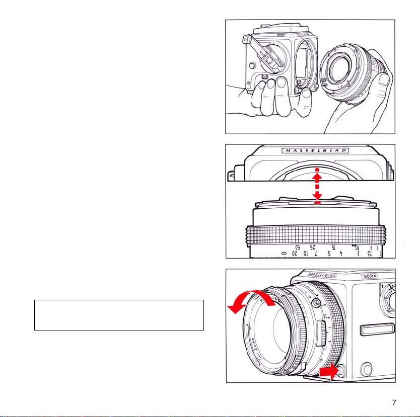
Lenses
Since the early 1950’s Hasselblad lenses have been
manufactured by Carl Zeiss in Germany. The Has-
selblad 503CX and 500 Classic use CF and C lens-
es made by Carl Zeiss With the exception of F-type
lenses, all Hasselblad lenses manufactured since 1957
can be used with the 503CX and 500 Classic. F-lenses
can only be used with the Hasselblad200 and 2000 se-
ries cameras. Use this manual to learn how to operate
your camera. The knowledge gained from reading it
will give you access to the Hasselblad potential. Ex-
ploiting the potential is left to your imagination!