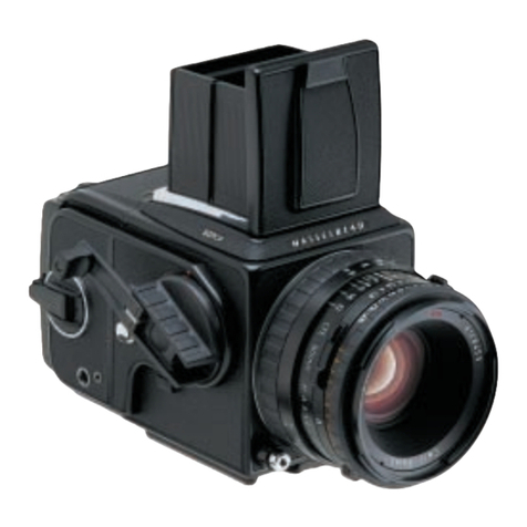
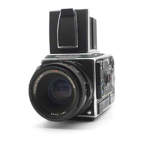
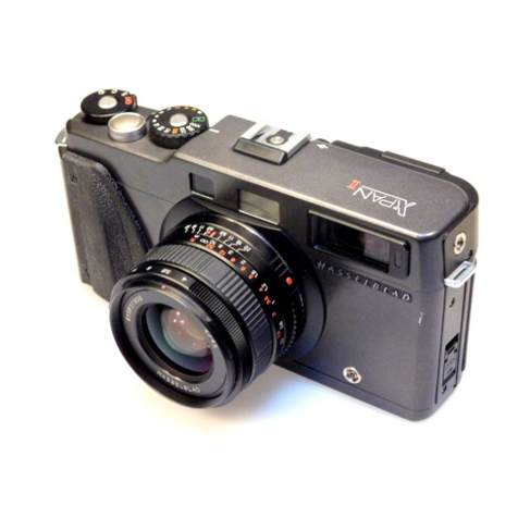
Hasselblad 905SWC User manual


I] A S S f T B T A D
9O5$wc
lnstructionManual
@
www.orphancameras.com

Welcome
to
the
Hasselblad
Camera
System
AsaHasselblad
owner,
youhaveinyour possession
acamera
of
exceptional
quality,
the
product
ofaninternationally
renowned
tradition
of excellence
in theworldofphotography.
lt gives
you
occess
totheworld's
largest
medium
formotcamera
system,
the
Hasselblad
System,
which
successfully
has
been
taken
to the
ends
ofthe
earthand
beyond
- into
space
- toeornits
worldwide
repu-
tationforquality
andreliobility.
Arange
ofaccessories
afford
greatflexibility
and
potentialfor suc-
cessful
photography
inalmost
anyapplicotion.
Among
the
different
camera
modelswithin
theHasselblad
System,
the905SWChas
a unique
position,
being
theonlymodelthat
is
notasingle
lensreflex
type.The
reason
is
thefamous
ZeissBiogon
CFi4.5
/38 mm wide-angle
lens.The
symmetrical
design
and a
veryshort
focal
length
of this
lens
leoves
noroom
foro viewfind-
ermirrorbetween
therear
ofthe lens
andthefilm.tnstead
ofbe-
ing attached
to a single
lensreflex
comero
body thelens
isper-
manently
attoched
to theshortand very
robust
diecostmetal
housing.
The
Hasselblad
905SWChas
odetachoble
opticalviewfinder
with
a built-in spirit level.Through-the-lens
viewingis possible
by
means
ofthe
speciolly
designedFocusing
screen
adapter
SWC
to-
gether
withany
oneofthemany
Hasselblad
viewfinders.

ii;t;ii:
i:r,i:!:i
TheHasselblod
905SWC
occeptsalldifferent
types
ofHasselblad
filmmagazinesfor 120,220
andPolaroid
typefilms
with6x6cm
and6x4.5
cm
imageformats.
Likeall Hasselblad
lenses
since
theearly 1950'swith fewexcep-
tions
, theBiogon
CFi4,5/38lens
ismanufactured
byCarlZeiss
in
Germony.
Thelens
canbefocused
downto0.3m (l ft.) and
pro-
videsafullimagecoveragewith
a 90"diagonalanglefield
ofview,
onexceptionallyhighdistortion
correction
andahighlyimproved
illuminotiondistribution.The
lenselements
havethehighly
effi-
cientCarlZeissT*
multi-loyer
anti-reflection
coating
onallglass-
to-airsurfaces.
Seealso
page14fordetoiled
information
onthe
optical
prop-
erties!
Thisinstruction
manual
provides
adetailed
description
ofhowto
operatetheHosselblad
905SWCcamero.Theknowledgegoined
fromcorefullystudyingit will giveyou occess
to theHasselblod
potentiol.
Exploiting
that potentialisleft toyour skilland
imaginotion!
Con
g
ratulations
o
n
y
our choice
ofduni
q
uecamero
!
tltitil
i:li:
,lt:t!!.|:
www.orphancameras.com

Contents
lntroductian
(jontents
5. Partsand
Components
6:,.
.G.ETTNG
STARTED
6. Lensshade
6. Lens
ProtectiveCover
7. Rear
Cover
MultiControl
7. Attaching
the
Magazine
7. Removing
the
Magazine
7. IheMagazineStatus
Indicator
7. Attaching
the
Viewfinder
7. Removing
the
Viewfinder
8. The
Winding
Crank
8. Strap
LugsandStrap
8. Removingthe
Strap
8. Holding
the
9055WC
8, OPERATING
DETAILS
Exposure
TimeExposure
Lock
Cable
Release
MultipleExposures
[ENs AND
SHUTTERFUNCTIONS
9.Shutterspeeds
and
Aperture
9, ExposureValues
9. Interlocking
ofShutterSpeed
and
Aperture
10.Focusing
and
Depth-of-field
10.Infrared
Photography
10,Flash
Synchronization
10.HyperfocalSetting
11,Loadingthe
Magazine
12.Film
Loadlndicator
12.Removing
the
Film
12.MagazineSlide
Holder
12.
FilmTabholder
12.
Film
Plane
position
12,
Magazine
for
PolaroidFilm
12.ViewfinderSWC
12.SpiritLevel
13.
lmage
Parallax
I3. OTHERUIEWFINDEf,S
.
13.FocusingScreenAdapterSWC
13.Using
theFocusingScreen
Adapter
14. Meter
prism
viewfindersPME45
andPME90
I
4..OlTrcAL PROPERTIES
14.MIF-function
14.Relativeillumination
14.RadialDistortion
15. ACCESSOR'ES
15.AccessoryMounts
15.Hasselblad
AccessoryChart
16.Comerocore
16.froubleshooting
16. Technical
Specificotions
17.Service
ond
Guorantee
8.
8.
8.
9.
9.

1.Viewfinderwithbuilt-inspirit
level 1&2
2. Rubber
eyepiecestray-light
protection
3. Shutter
release
buttonwiththreaded
cable
release
socket
4. Magazine
catch
button
5.Time
exposure/TTLviewinglock
6.Filmwinding
crank
7. Framecounter
8. Magazine
status
indicator
9. Windingcrank
10.Focusing
ring
11.Exposurevalueinterlock
button
12.Exposurevalueindex
13.Exposurevalue
scale
(EV)
14.Aperturering
15.Externallens
accessory
mount
16.Lens
shade
17.Internallens
accessorymount
18.
Shutterspeed
ring
19.Shutter
speedscale
20.Aperture
scale
21.Depth-of-field
scale
22.Lens
centralindex
23.Focusing
distance
scale,
inches/feet
and
metres
24.Viewfinder
mount
25.Viewfinder
releasecatch
26. Magazine
slide
27. Magazinehooks
28.
Strap
lug
29.
Pcflash
terminal
30.Magazine
supports
31.Tripod
sockets,1/4"
and3/8"threads
32.
Quick-coupling
plate
33.
Magazine
slideholder
34.Film
tab
holder
35.Magazine
slide
holder
slot
36.Filmloadindicator
37. Filmholderkey
38.Filmholder
*Acute Matte D designedby MINOLTA
5
www.orphancameras.com

ln the text, the positions of componentsare
described
in relotionto thecamera
as
you seeit
when
tokinga
photograph,
i.e.the
lens
is
onthe
front,theviewfinder
onthetop,
and thewinding
crankison theright handside.
Therelevant illustrations to a particular sec-
tion are indicated by the figures beside the
smoll headings in the text.
This
sectiondescribesthesteps
youmust
taketo
moke
thecomerareody
touse.
You
willfindcom-
pre
h
ensive
inform
ationonhow
too
perate
thecam-
erainthefollowingsections.Paragrophnumbers
in
italic
intheheodlines
and
inthetextrefer
tocorre-
sponding
illustrations
intheattachedillustrations
booklet.
Ensure
thatthecomeroiswound
beforeottaching
omogozine.Thewinding
cronkon
the
right
hond
side
ofthecomero
islocked
against
clockwiseroto-
tion
ifthecameroisfullywound.
Counterclockwise
rototionispossible
osthewinding
cronk
isona
ratchet.
lfthe
crqnkis
notlocked,
rotateitclockwise
until
itstops.
Removethelensshade
by
pushing
itagainst
the
lens
front
and
rotate
counter
clockwisetostop.Thelens
shadeisnowfreefrom
thebayonetandcan
be
re-
movedfrom
the
lensfront.
Attaching
thelens
shadeismadebyreversing
the
procedureabove.Align
theindexon
the
lens
shade
vertically.
Front protective cover '
4i
Turn
thecover
(bayonet
fitting)in
thedirectionof
thearrow
(counter-clockwise)
andremove.

Reorcover MultiControl
Depressthecatch,tilt thecoverbackwards,and
lift
it off.
Attaching the magozine 6, i
Ensurethatthemagazineslideisfullyinsertedand
thatthemagazinestatusindicatoriswhite.If the
indicator
is notwhite.referto theinstructionon
page7.
Restthe magazineonthecamera's
magazine
sup-
portsandensurethat
itis
properly
located.
Carefully
swingthe
magazine
towardsthecamerabody
and
checkthatthe
camera'smagazinehooksfitintothe
magazine
slots.
Push
the
magazinegently
but
firmly
againstthehookswhileslidingthemagazinecatch
buttontothe
right.
Releasethe
magazine
catchbuttonwhenthe
maga-
zinemakescontactwiththe
rear
plateofthecamera,
andpushit tothe
left
toensurethat
it hasreached
thelockedposition.Removethemagazineslideand
insertitintheslideholderonthebackofthe
maga-
zine
(see
page8).
Removing the mogazine C ,
It isadvisabletohavethecamerafullywoundand
themagazinestatusindicatorshowingwhite.Ifthe
magazinestatusindicatorshowsaredsignal,then
windthecamera
first.
Insertthemagazineslide
into
the
magazine
withthe
hingetowardsthefrontofthecamera.
Slide
themagazinecatchbuttontotheright,tilt the
magazinebackandlift itoff
the
magazinesupports.
Notethatthe cameracannotbeoperated
when
fi o magozine with theslideinsertedis
attached
z-:J 1e it. The mogazine connot be removed with-
out firstinserting
themagazine
slide.
Themagazine stotus indicotor g, lA;,;;ll,:;,;,
The
statusindicatorontherighthand
sideof the
magazineshowswhetherthe magazineisready
to
operate
(white)
ornot
(red),
i.e.thefilmhasnot
been
advancedafterthelatestexposure.
Donot
attach
amagazine
showingwhitetoacamera
that
isnotwound!
Windthecamerafirstbyafull
turn of
the
winding
crank,otherwiseyouwill lose
one
frame.
Do not attacha magazineshowingredto a fully
woundcamera!
It couldresultin anunintentional
doubleexposure,
since
theframeinpositioninthe
magazineprobablyalreadyisexposed.
Ifthestatusindicatorshowsred,release
thecamera
(page
8)beforeattachingthemagazine.Then,
when
youwindthecamera,the
filmwill beadvanced
to
thenextframe.
Attaching. the uiewfinder l.t
With thecatch
facingforward
slidetheviewfinder
into theaccessoryandviewfindermount
until it
positively
latches
ontothestud
located
at
the
front
endofthemount.
Removing
theviewfinder ,i$.
Releasetheviewfinderbypressingtheviewfinder
catchinthedirectionof
the
arrow
whileslidingthe
viewfinder
towardsthe
rear
ofthecamera.

www.orphancameras.com

Thewinding cronk
Thepermanently
attached
windingcrank has a
ratchet
to enable
theoperator
to rotate
thecrank
counter-clockwise.
This
design
allows
youtoposi-
tion
thecrank
toanydesired
starting
pointand
op-
erateit either
byonefull turnorbyapumping
ac-
tion.Thelatter
isnecessary
whenthecamera
isused
withamagazine
forPolaroid
film.
Straplugs,
attachingthestrap 15,16
Place
themain
bodyof
thestrapclipover
oneof
the
camera's
straplugs.
Press
thetipofthe
cliptowards
the
camera
whilepulling
backonthe
strapso
that
thestrap
clipslides
overthe
straplugandlocks
into
position.
Removing
thestrap Ii
Liftthe
cliplocking
platehigh
enough
topassover
the
straplug.
Slidetheclipforward
inthedirection
away
from
thestrap
untilit isfree.
Hotding the ilL\SWC 18
You
will findthat holding
thecamerain yourleft
hand
as
shownin theillustration
isthe
most
con-
venient
gripwhen
thecameraishand
held.The
right
handis
thenpositioned
to steady
thegripand
the
index
finger
on
the
right
handis
usedto
operate
the
camera
release
button.
Exposure
The
shutterrelease
buttonfor the905SWCis situ-
atedonthe
topofthecamera.
Ensure
that
thecamerais
woundand
the
magazine
slideremoved
beforean
exposureismade.
Time expo1ur-e-
loc_k 1gt,,
Thetime
exposurelocklever
has
twosettings:
O = Normal setting used
for all shutter speeds
except'B'.
T= The release
button locks after being de-
pressed
and remains locked until the le-
ver isreturned to the 'O' setting.
The'T' setting
canbeusedfortimeexposuresin
conjunction
with
theshutter
speedbeing
setto'B'.
The
windingcrankis locked
until theleveris re-
turnedto
the'0'setting.
This
lockingfunction'T'will
notoperate
when
/\ acablerelease
isused.With
the'B' settingon
4*:J theshutterspeed
theuseof a coblereleoseis
recomm
ended
(see
below).
Cable release *4.
Normally
thecombined
use
ofacablerelease
anda
camerasupportisrecommended
for
shutterspeeds
slower
thanli60s.
The
cablerelease
isattached
by
l4

screwing
it intothethreadedsocketin theshutter
release
button.
Multipleexposures :ii'
Thecamera
is
designedtopreventaccidentaldouble
exposures.
However,intentional
double
andmulti-
pleexposuresonthesameframecanbecarriedout
asfollows:
l.Depressthe shutter release
button and make
theinitial exposure.Themagazinestatusindi-
catorwill changetored.
2.Insertthemagazine
slide,
removethemagazine.
3.Windthecamerabyrotatingthewindingcrank
one
full revolutionor by usingapumping ac-
tion until thecrank stops.
4.Replace
themagazine
and
remove
theslide.
The
unit
isnowready
to
make
asecondexposureon
thesameframe.Youcanmakeadditionalexposures
inthesamemanner.
ln thiscasean exposure
is
made with o maga-
zineshowing aredstatus
indicator.Thisrepre-
sentson exception to the norm.
Shutterspeedandaperture- ,2i,
Theshutter
speedselectorringistheringlocated
closesttothe
front
ofthe
lens.
Thedesired
shutter
speedissetopposite
the
lensindex.
Thewhitescaleshowstheshutterspeeds,and
the
orangescale
theexposure
values
(EV).
Theapertureringislocatedbehindthe
shutterspeed
ring.The
desired
lens
aperture
is
alsosetopposite
the
lensindex.
Exposurevolues
Thecombinationofapertureand
shutterspeedset
oppositethe
lensindex,
determinestheexposure.
Everycombination
ofshutterspeed/aperturehasan
equivalentexposurevalue
(EV),
whichyoucanread
orsetagainsttheorangeEVindexonthe
sideofthe
lens.
Exposurevalues
can
alsobedetermined
byusingan
exposure
meterhaving
anEVscale.
lnterlocking of shutter speed
andaperture #
Ifyou
wanttochangeeithertheshutterspeed
or
ap-
erturewithoutchangingtheEV
(Exposure
Value),
youcan
interlock
theshutterspeedandaperture
settingrings.Thisiscarriedout
bydepressingthe
9
23
www.orphancameras.com

interlock
buttonontheright of theaperture
scale,
thenturningtheinterlockedrings
to thedesired
aperture
andspeedcombination.Wheninterlocked
the
rings
move
together,
increasing
or decreasing
the
apertureandshutterspeedwhilemaintaining
theEVfor
correctexposure.
Focusing_
and depth-of-fietd 2i,
The
focusingringis thewide
ringwitha knurled
rubbergrip,
setclosesttothecamerabody.Thedis-
tancescalesappearonthisring.Thelensisfocused
by rotating
thefocusing
ring until the measured
orestimated
distancebetweenthesubjectandthe
film
plane
appearsoppositethe
lens
index.Thedis-
tance
is
showninwhiteformetres,andin
orange
for
inches/feet.
Objectscloser
or
further
awaythantheselecteddis-
tancewill appear
sharp,within certainlimits.The
range
ofsharpfocus,i.e.
depth-of-fieldvarieswith
theaperture.
The
depth-of-fieldavailableat anygivenaperture
setting
canbereadoff thedepth-of-field
scaleon
both
sidesofthecentralindex.The
setting
inthe
il-
lustration
indicateshow
to read
thedepth-of-field
scaleatan
apertureof
f/l l,i.e.
approximatelyfrom
0.65m
(2.3
ft.)to1.5m
(s
ft.).
lnfrared photography 26;,,fi,
Infrared
(IR)
rays
(wavelengths
longer
than800nm)
form
animageona
plane
furtherawayfrom
thelens
thantheimageplaneforvisible
light.To
compen-
sate
for
thisdifference
you
have
toalignthechosen
10
distanceagainstthe
red
IRindexinsteadofthenor-
mallensindex.Proceed
asfollows:
l.Establish the distance to the subject either
by measuringor by focusingon the focusing
screenadapter
(see
page13).
2.Notethe measureddistance
or mark the dis-
tance
pointonthe
focusing
scaleoppositethe
lensindexline.
3.Adjustthefocusingring until theestablished
distance
point isopposite
theredIRindex.
Flashsylchronization tt,
Thebuilt-in shutterin theBiogon
CFi
lensis fully
synchronized.Aflashconnected
tothe
PC
terminal
fires
whentheshutter
isfullyopen.
When
inserting
a
flashcordinto
thesocket,
keep
the
lockbuttonpressedin.0n release,
thecordwill be
lockedinto
place.
Toremove,
press
inthe
lock
but-
tonagain.
Electronicflash
units canbe usedat all shutter
speeds
(B
andI s
*l/500
s).
Hyperfocolsetting ,.21y9*,31.;,
Theveryshortfocallengthofthe38mmBiogon
CFi
lensprovides
botha90'angleandalargedepth-of-
field.Thisallowssuccessfuluseof thehyperfocal
distancesettingmethod.Itisbased
onthe
fact
that
thesharplydefinedareaofaphotographicimageex-
tends
both
infrontofand
beyondthe
focusing
point
as
describedinthesectioncovering
'Focusing
and
depth-of-field'.
Thedistanceslimiting the sharply
definedareaareknown
asthe'near
limit' andthe
'far
limit'.

To
usethe
hyperfocaldistancesettingmethod,
first
determinethe
EV-settingandthenselectthe
slow-
estapplicableshutterspeed.
Thiswill giveyouthe
smallestpossibleaperture,
and
therefore
the
largest
depth-of-field.
Rotate
the
focusing
ringsothatthe
infinitymarkissettothefar
limit,i.e.opposite
the
selectedaperture
number
tothe
rightofthe
lensin-
dex.Now
you
can
read
the
nearlimit distanceop-
positetheaperture
numbertothe
left
ofthe
lensin-
dex.Usingthis
method
you
willgetan
imagethatis
sharp
fromthenearlimittoinfinity.
Example:ThemeasuredEV
is13.The
selected
shut-
ter
speedisli60s.
Thisresultsinanaperturevalue
off/ll. Bysettingthe
infinitymarkat
f/tl onthe
far
limit,the
nearlimit
will
landatadistanceof1.2m
(4ft.).
Atthewidestaperture
(f14.5)
thenear
limit is3m
(10
ft.)andatthesmallestaperture
(f|22)
the
near
limitisascloseas0.65m(26
in.).
Loading the magazine ;32t31
Themagazinemaybeloadedonoroffthe
camera.If
itistobeloadedoffthecamera,then
themagazine
slidemustbe
inserted,itsflatsidetowardsthe
rear.
Thisallowsremovalofthe
filmholderforloading.
Follow
theprocedure
below
incorrect
ordertoload
themagazine.
CW
= clockwise
C-CW
= counter-clockwise
32.
Foldoutthefilm holder
key.
33.Rotatethe key C-CWand withdraw the film
lrolder.
34.Place an empty take-up spool under the
groovedknob of the spool clamp bar. Insert
aroll of film under the other end of the bar,
turnedthesame
wayas
in theillustration. Be
sure
to removeall thepaperbandsurround-
ing anewroll offilm!
35.Turn thefilm holderkeyCWto openthe film
clamp.
Pull 8-10cm (3-4 in.) of paper
back-
ing off the film roll and slide the edgeunder
theclamp.
36.
Insert the tongueof the backing paperinto
theslot
in thetake-up
spool.
37.
IMPORTANT!
Turn thegroovedknob CWuntil thearrow on
thepaper
backing
isalignedopposite
thetri-
angular film load index on the spool clamp
bar,but no further.
38.
Turnthefilm holderkeyC-CWand
insert the
film holderinto themagazine.
Ensurethat it
is correctlypositioned.
Turn the film holder
key CWto lock the film holder in the maga-
zineand then fold it backin place.
39.Foldoutthefilm winding crank androtateit
CWabout ten turns until it stops.Turn the
crankC-CWif necessary
and
foldit in.
A Align thearrow on thepaper backingof oll
[-* UORD btack
&white
films
ogainst
theoblong
index
(and
nofurther)
onthespoolclamp
bar
ondnotthetriangular
indexasnormal.
Thefigure
(l) will nowbedisplayed
in theframe
counterwindow,
indicatingthat the magazine
is
loadedand
readyforuse. 1',t
www.orphancameras.com

The
magazine's
film
winding
crank
isblocked,
but
only
at
frame
(l). Apartially
exposed
film may
be
wound
offat
any
frame
after
that.
The
frame
counter
isautomatically
resetwhen
the
filmholder
iswithdrawn
from
the
magazine.
Film toad
Inthe
centre
ofthe
film
holder
key
there
isacrescent-
shaped
indicator
window
thatshows
white
whenthe
magazine
isfreshly
loaded.
Itgradually
changes
to
redasthe
filmiswound
through.
Anall
red
indica-
tor
shows
that
the
film
isusedup
or
thatthe
maga-
zine
isempty.
::::i.:::,::;i:i:
Afterthe
last
frame
has
beenexposed
and
the
film
advanced,
the
magazine
blocks
thecamera
against
furtherrelease.
Toremove
the
exposed
filmfold
out
the
film
winding
crank
and
rotate
itclockwise
until
you
can
feelthat
the
filmis
leavingthe
supply
spool.
Withdraw
the
filmholder
fromthe
magazine
and
re-
movethe
film.
:1:::i:i:::i
Mogazine slide holde
0nthe
rearofthe
magazine
isthe
slide
holderwhere
the
magazine
slide
could
bestowed
away
whennot
inuse.
Turn
theslide
withthe
hinge
towards
the
rear
to
fold
thebow
fullyintothe
slide
holder
recesses.
.::,-:a:::+::
FilmTab
Holder #i
The
end
tabofthefilmpackcan
be
inserted
in the
12
holderon
the
backof
the
magazine
as
areminder
ofthekind of film thathasbeen
loaded
intothe
magazine.
Film plane positio_n .
The
filmplane
position
isrepresented
by
thechrome
and
leatherette
contact
linebehind
themagazine
slideinsertion
slit.
Magazine for Polaroid fitm $;'
When
amagazine
forPolaroid
filmisused
with
the
905SWC
the
filmwinding
crank
cannot
complete
a
full
revolution.In
order
towind
thecamera,
fold
out
the
film winding
crank
and
move
it upanddown
withapumping
motionuntil
itstops.
Theoptical
viewfinder
can
be
attached
tothe
mount
ontopofthecamera
body.
Itshows
an
imagethat
is
slightly
larger
than
the
image
recorded
onthe
film.
There
arecorner
marksthatindicatetheheight
of
the6x4.5
cmformatand
also
a centre
mark.
The
lensscales
canbe
seen
through
acrescent-shaped
bifocal
optical
system
inthe
lower
partofthe
view-
finder
image.
Theoptical
system
allowsthe
wearing
ofspectacles
without
problem.
The
rubbereye-cuP'
which
protects
against
stray
light,
maybe
folded
for-
ward
if preferred.
ii:::i::rirri:i!
Sp,irit
leuel ffi
Atransparent
spirit
level
is
built
intothetop
ofthe
viewfinder
body.
Thespirit level
is displayed
be-

neaththeviewfinderimagearea.Ithasanaccuracy
ofloforeachmmofbubbletravel,
i.e.
as
long
asthe
bubblestayswithin the centrecirclethedeviation
ofthecamera
positionfromhorizontaldoesnotex-
ceedlo.
lmage parallax '4V,';
Thepositionoftheviewfinder
- aboveandslightly
behindthelenscausesaminordeviationbetween
theareacoveredbytheviewfinder
and
that
covered
bythelens.Thisarea
covered
bytheviewfinder
is
coloured
redin figure47.Thecentre
of theview-
finderareaislocatedabout7.5cm
(3
in.)
abovethe
centreofthelensarea.Thedifferences
in location
andsizeoftheviewfinderand
lensimage
areas
are
illustratedin thefigure.At successivelylongerob-
ject
distancestheparallaxbecomessmallcompared
withthe
fieldof
view.
For
accurate
compositionand
focusingusethefocusingscreenadapter
(see
below).
AllHasselblad
viewfinders
canbe used
on the
905SWCtogether
withtheFocusingscreenodapter
SWC
(Cat.
No.41050).
Focusings.c-re.en-.a-_d.ap_t-er
l.
WC-._
You
can
usetheFocusingscreenadapter
SWCto
checkthedepth-of-field,theexactarea
coveredand
imagecomposition.Theadapterattaches
to the
camerabodyinthesamewayasthe
magazine.The
image
onthescreen
canbeviewedthroughany
Hasselbladviewfinderand
focusinghood.
Using the focusing screenadapter
l. SettheshuttertoB.
2.Setthelensto themaximum aperture
(f/a.5).
3.Setthetimeexposurelockto'T'and pressthe
shutterreleasebutton.
/N Thecablereleose
cannotbeused.The'T'lockis
IA notoperotive
when
thecoble
release
is
used.
4.Tocheckthe
depth-of-field
selectthe
appropri-
ateworking aperture.
5.
After checkingreturn thetime exposure
lock
to'O'.Thisclosestheshutter.
6.
Wind thecamerato cockthe shutter.
Replace
thefocusingscreenwith amagazine.
13
www.orphancameras.com

Meter
prism
viewfrnders
PME45
iii prrlei
Meter
prismviewfinders
PME45
and
PME90
canbe
used
foraccurate
lightmetering
onthescreen
of
the
Focusing
screen
adapter
SWC.
The Meter prism viewfinders
PME3,
PME5and
PME5l
also
provide
correct
metered
values.
However'
oldermeter
prism viewfinders,
Focusing
screen
adapters
ortheir
combined
use
require
a
reduction
of
the
metered
value
byl-2 stoPs.
Experiment
todetermine
the
precisereduction!
Even
atthe
widest
aperture
the
image
produced
by
the
Biogon
T'tCFi
4.5138
mmlens
ischaracterized
by
extraordinary
sharpness
and
brilliance.
Thisto-
gether
withthe
very
lowradialdistortion
andthe
remarkably
widefocusing
range
from 0.3m to oo
makes
it very suitable
for architectural,
fashion,
industrial
and
technical
photography
or
whenever
thehighest
image
qualityis required.
Thegraphs
(figs
a9-51)
represent
the typicalcharacteristics
of MTF (Modulation
Transfer
Function),
Relative
Illumination
and
Radial
Distortion.
In thegraphs
the
horizontal
axis
represents
the
distance
fromthe
image
centre.
14
MTF-function $0.,
Thegraph
shows
the
Modulation
Transfer
Function,
which
isarepresentation
of
theoverall
lensquality,
foraspatial
frequency
of20line-pairs/mm
atanap-
erture
off/8.
Aflatcurve
witha
relative
value
near
1.0
indicatesa highquality
recording
with small
lossesonly.
Relatiue illumination !$'fx'
Thisgraph
represents
thefall-offof illumination
from
the
imagecentre,
which
isgiventhe
value
1.0,
towards
theedges.
It includes
"naturalfall-offl'as
well
asvignetting.
Radial distortion
This
graph
represents
thedislocation
in % ofthe
distance
fromthe
image
centre
ofanimage
point
fromitstheoretical
position.
Translated
toabsolute
values
the
max.distortion
ofthe
Biogon
CFi
lensis
farlessthan
0.1
mm.
.EE

Accessory mounts 55'i
Theundersideof
thecamerabodyhas318"andll4"
threadtripodsocketsinthecentreofthequickcou-
plingplate.
The
plateandsocketacceptflashgun
bracketsandtheplatealsofitsandeasilylocksinto
the
HasselbladTripod
quick-couplings.
Thelenses
accept
060
filtersand
lens
shadesonthe
front
bayonets.
Hasselblad.
ac.cesso.rychart ,fiE
The
accessorychartindicatestherangeofaccesso-
ries
availablewithintheHasselbladsystem.Please
refer
tothe
Hasselblad
productcatalogue
forcom-
plete
information
ontheentireHasselbladcamera
system.
t5
www.orphancameras.com

Yourcamera
isbuilt
togivelong
andtrouble-free
service,
especiallywhenyou
followthemaintenance
andcare
advice
attheend
ofthis
manual.
Ifhoweveryouencounter
anyoperating
dfficultiesbecause
youare
not
famil-
iarwiththe
Hasselblad
cameraslstem,
the
following
table
mayhelpto
resolvethem.
lf the
problem
persists
and
thecamerc
is still
underguarantee,
youshouldcontact
yourHasselbladdealer.
If theguarantee
hasexpired,
you
shouldcontact
aHasselbladauthorised
Service
Center
for advice.
Youcanobtain
theaddress
ofyournear-
estservice
centre
from
yourdealer,
distributor
ourhomepage
orbycontacting
usdirectly.
PnoeLrfrfi PosstsLE
CAUsE REMEDY
You
cannotoperate
theshuttet .Themagazine
slide
isstillin
place ' Remove
theslide
re|eacebutton..|..:.;l.::':.:.:;:l:..::
' ' , ' .
Thr
camera
isinthereleased
position .
Windthe
camera
'i , . :: -
Ihe
release
Uution
ramaint .
Thetimeexposure
lock
is
in
the 'Returnthe
locktotheOpposition
defresseA '';1.'...'...i,,.i...'''
.;..,'..,.i,.
T-position
''':','':'
..'.'.'''''
You
unnot
rem3vethe
magarine
.Themagazine
slideisnotfully
inserted 'Insertthemagazine
slidecompletely
SERVICEAND MAINTENANCE GUARANTEE
WhileHasselbladequipmentisextremelyreliableand
lf your camera
was
purchased
from an authorized
durable,camerasandlensesthatareinconstantin-
Hasselbladoutlet,
it iscovered
byan international
tensive
usein aprofessional
environment
should
be guaranteefor
one/ear.
Further
detailsontheguaran-
maintained
andservicedby
an
authorizedHasselblad teecanbe
found
on
page18.
Service
Center
atregular
intervals.
Furtherinforma-
tion
onservice
and
maintenancecan
be
found
on
page
18.
16

Technical
Specificatioils,
fihd
www.orphancameras.com

EQUIPMENT
CARE
A Hasselblod
camera
is designed
to withstandthe
rigoursof
professionol
use
inmostenvironments.
To
avoidthe possibility
of damage
however,
it should
be
protectedfrom
the
following:
Extremesof tem
peratute.
High temperotures
can hovean adverse
effecton
both thefilm and the comera.
Forthisreoson
you
should
notkeep
yourcamero
in places
where
it will
gethot,such
as
indirectsunlight
oronoshelfabove
o rodiator.
ln tropical
environments
fungus
growth
can
be
prevented
byensuring
yourequipment
iskept
inonarea
wheretheairis
circuloting.
Frequent
rap-
idand
severetemperature
changes
cancause
prob-
lemssuch
asthecorrosion
ofelectricol
contocts,
and
shouldtherefore
beavoided.
When
workingin ex-
tremely
coldtemperatures,
cameras
and especiolly
lensesshould
be
protected
asmuchas
possible.
Dust and grit.
Youshould
takecare
to
prevent
dirtofany
kindfrom
getting
into
yourcamera.
Whentaking
photographs
in coastal
areas
forexample,
thecamera
should
be
protected
fromsand
andsolt
watersproy.
Dustonthelens
glass
surfacecan
be
removed
witha
blower
brushor
averysoftbrush
ifnecessary.
Smeors
on thelens
glass
should
betreoted
with greatcou-
tion. Light smears
couldbe removedwith a high
quality lenscleoning
solution
onasoft,
cleantissue.
Heavysmears
should
betreated
bya
Hasselblad
serv'
ice
center.
tfindoubt
donotclean
lens
glossyourself.
Always
be
verycareful
nottoscrotch
the
lensortouch
anyof the
glass
surfaces
with
yourfingers!
18
Service.
Foultlesscamera
performonce
isessentiolto
the
pro-
fessional
photographer.
lt is therefore
advisable
to
checkthatyour comero
isfunctioningcorrectly
be'
forean important ossignment.
Youshouldalsore-
turn
yourcomeratoaHasselblod
Authorised
Service
Centre
foroccasionalchecking
and
preventive
moin-
tenance.
lf your comero
is usedconstontly
ond in-
tensively,
exposing
for example
hundredsof rollsof
film
perweek,check-ups
every
six
monthsare
recom-
mended.
HasselbladService
Centres
havetheexpert
staffand
speciolised
equipment
necessoty
toensure
that
yourcamero
remains
inperfect
workingorder.
Impact,
Yourcamerocan be damogedby severe
physical
shocks.
While
youwillobviously
trynottodropit,
you
shouldalsotake
care
not toleove
it whereit can
fall
orbe
knockedtotheground,
orrollobout,
suchoson
the
seatofacar.
Troubleshooting.
Yourcamero
isbuilttogive
longandtrouble-free
serv-
ice.lf howeveryou
encounter
onyoperating
difficul-
ties
because
youore
notfamiliarwiththe
Hasselblad
comero
system,
thefollowingtoblemayhelpto re-
solvethem.
Guarantee.
tf you purchasedyour camero
from an authorised
Hasselbladoutlet,it is covered
by on international
guarontee
for oneyear. The
guarantee
document
andaregistrationcord
oresupplied
withthe
comera.
Keepthe
guarontee
document
carefully,butfillinthe
registrationcardand
return
ittoyour Hasselbladdis-
tributor.
Other manuals for 905SWC
1
Table of contents
Other Hasselblad Film Camera manuals

Hasselblad
Hasselblad 501CM User manual

Hasselblad
Hasselblad 503CW-CFV II User manual

Hasselblad
Hasselblad 503CX User manual

Hasselblad
Hasselblad D 1600 F User manual

Hasselblad
Hasselblad H2F - User manual

Hasselblad
Hasselblad 503CW User manual

Hasselblad
Hasselblad 500 C User manual

Hasselblad
Hasselblad 2000FC User manual

Hasselblad
Hasselblad 2000FC/M User manual

Hasselblad
Hasselblad Xpan User manual