HATO 180C User manual

HATO 180C / 200C
GARAGE DOOR OPERATOR
USER’S MANUAL

2
OUTLINE
1. Safety instructions………………………………3
2. Main features …………………………………4
3. Technical specifications ………………………5
4. Check …………………………………………5
5. Installation and adjustment ……………………6
6. Programming …………………………………10
7. External terminal connections…………………16
8. Maintenance …………………………………17
9. Troubleshooting ………………………………17

3
INSTALLATION MANUAL
Our compliments for your excellent choice. The HATO 180C/200C electro-mechanical gear
motor has been produced for reliability and high quality.
This Manual will offer information you may need to install your gear motor assuring long-lasting
performance and to safeguard your safety. HOWEVER CAUTION IS UNQUESTIONABLY
INDISPENSABLE AND NOTHING IS BETTER THAN PREVENTING ACCIDENTS.
CONFORMITY DECLARATION:
It’s in accordance with Machine Directive 2006/42/WE and following modify.
It’s in accordance with the following directive CE:
Electromagnetic compatibility Directive 2014/30/UE and following modify.
Low tension Directive 2014/35/UE and following modify.
Radio directive RED 2014/53/UE
Have been applied the following harmonized norms:
EN ISO 12100:2012; EN 60204-1:2010; EN 60335-2-95:2015, EN 301 489-3 V1.4.1:2006; UNI
EN 12453:2002, where applicable EN 12445:2002
Current declaration are available on website
1.Safety instructions
Carefully read and follow all safety precaution, warnings before attempting to install and use
this garage door operator, incorrect installation can lead to severe injury.
The installation should be carried out by a qualified technician.
To avoid electrical shock, disconnect the power cord from the mains power outlet before
doing any repairs or removing the cover.
The door operator must be grounded.
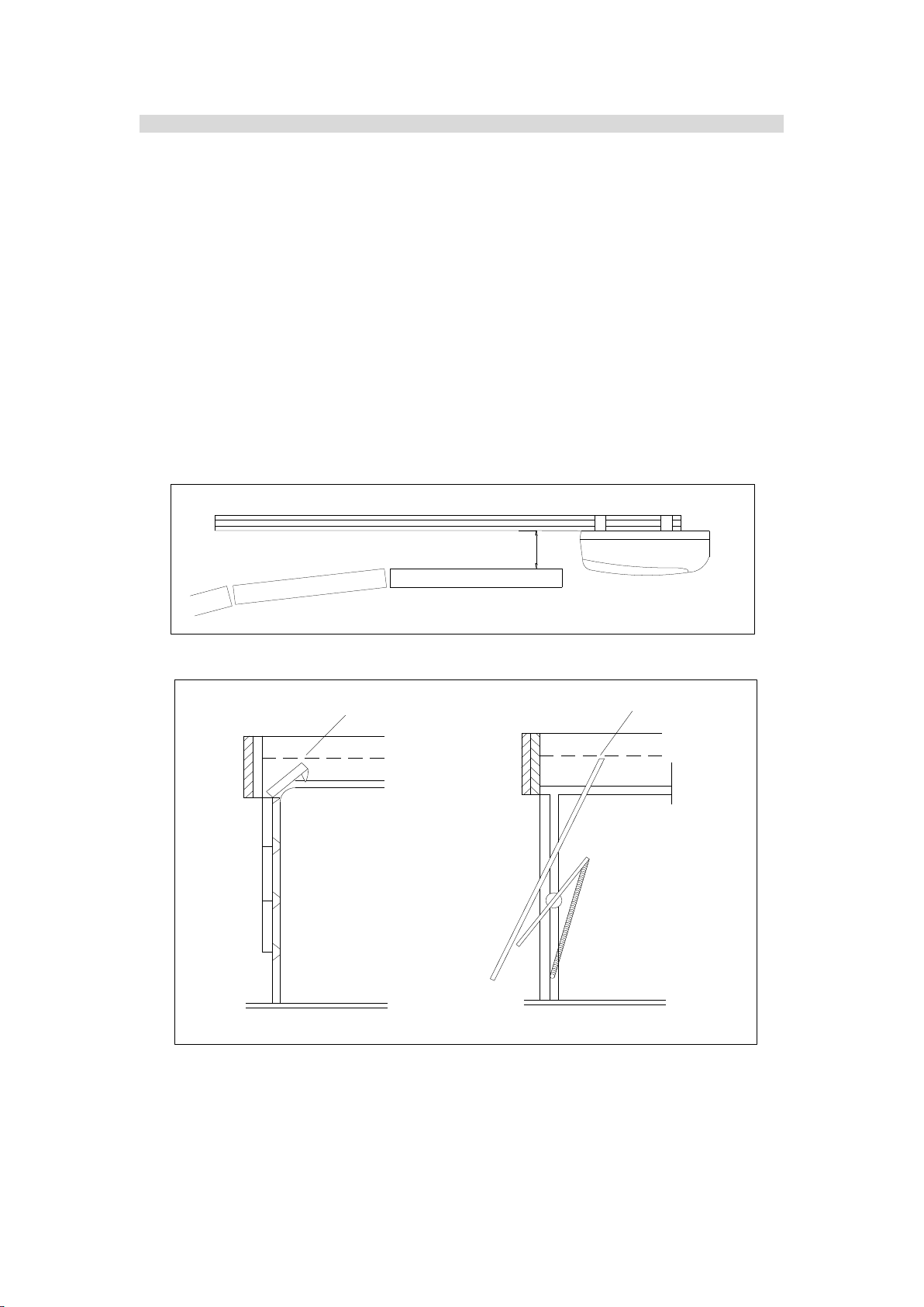
Before installation of the door operator, the door should be carefully checked for being
kept well balance. The door must be in good working order. Open and close the door
manually, make sure the door can be moved smoothly.
No one or vehicle is allowed to enter or leave the garage while the remoter is being
installed, do not allow children to play near the door.
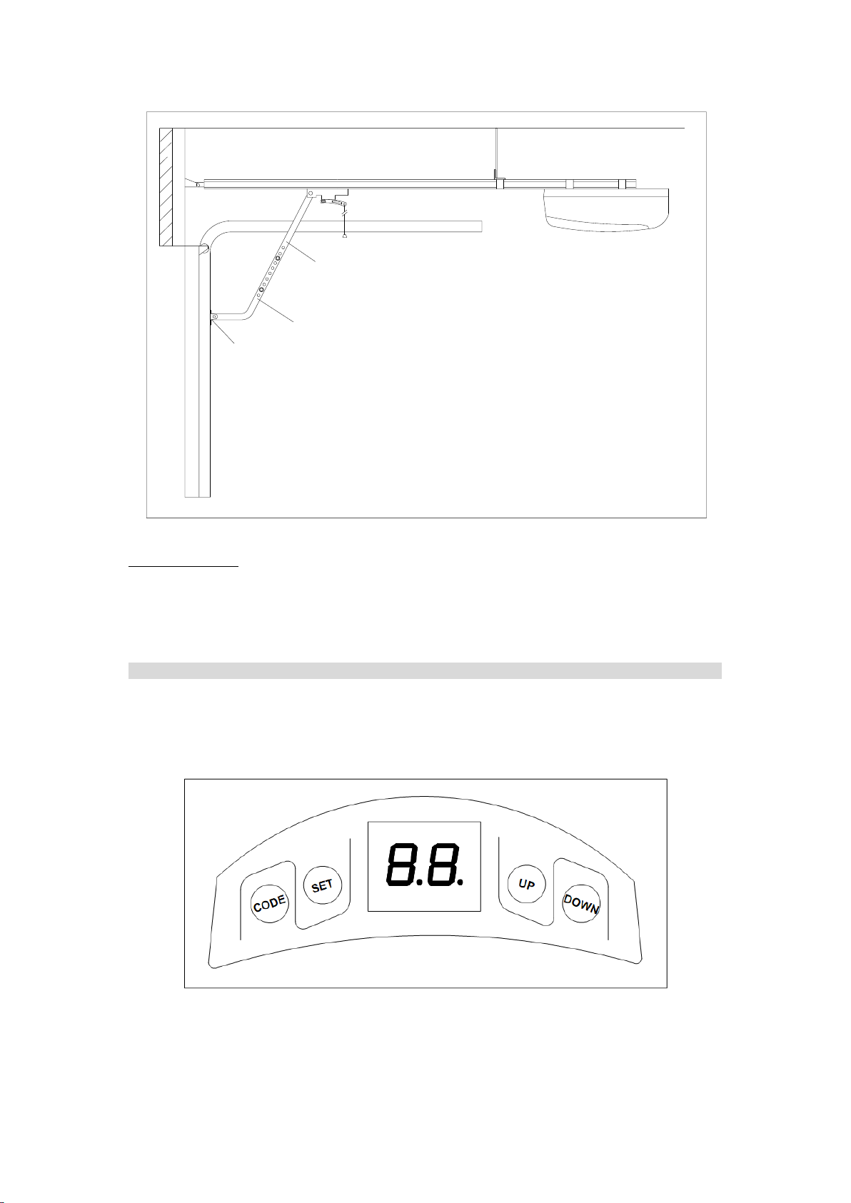
Locate any fixed control: within sight of door but away from all moving parts of the door
and at a height of more than 1.5m above the ground to avoid children reaching it.
Keep remote controls away from children, to prevent the door operator from being
activated involuntarily.
When opening or closing the door, do not attempt to walk or drive through the door.
The door should only be operated when it can be observed to avoid accidents.
Install and adjust the manual release so that the handle hangs less than 1.5m above the
floor.
Our company reserves the right to change the design and specification without prior
notification.

4
During the installation and the use of the automation, pay attention to the following safety
rules:
Distance security!
Mechanisms moving!
Do not install automation in an environment saturated with explosive mixtures!
Electric Shock!
Use gloves!
Use welding glasses!
Maintain ear protection!
Failure to comply with the instructions above may result in personal injury or property damage.
Our company does not accept responsibility for damage or injury resulting from installing this
operator.
2. Main features
The door operator is designed for garage door.
The control unit regulates all the necessary functions such as automatic lighting control,
automatic memory, automatic close, automatic reverse and photocell protection etc.,
extremely quiet and smooth operation.
Courtesy light will turns on in using and turns off after 3 minutes.
The operator memorizes the limit positions and unique braking system that slows the unit
down at the end of its travel. Soft start and soft stop control guarantees extremely smooth
and quiet operation.
Automatic reversion on obstruction during closing procedure.
The controller has a security LOCK function which prevents operation of the door from
transmitter.
In the event of power failure, the release device makes it possible to open and close the
door manually.
Hopping code remote control with max. 20 pcs hand transmitters.
Wiring terminals for battery, button switch, infrared photocell etc.

5
3. Technical specifications
Tools required
A ladder and Tape measure
Electric drill and assorted drill bits
Screwdriver
Spanner / Wrench
Multimeter / Test pen
Hacksaw / Cutter
Pliers / Hammer
Use a helper if possible to assist with the installation.
4. Check
After receiving the product, you should make an unpack-inspection, in which you should check
whether the product was damaged. If you have any problem please contact dealer.
Fig.1
Model
HATO 180C
HATO 200C
Motor power
80 W
100 W
Lifting capacity
800 N
1000 N
Max. door size
8 m2
12 m2
Power supply
220X(1±10%)V AC 50-60Hz
Motor
24VDC
Ambient temperature
-20ºC~+50ºC
Working humidity
≦90%
Courtesy light time
3 minutes
Radio frequency
433.92 MHz
Transmitter type
Rolling code
Transmitter battery
27A 12V
Bulb
24V 5W
1.Powerhead (x1) 3. Shuttle&Manual release cord(x1)
2. Chain drive rail assembly (x1)
6. Door bracket (x1)
5. Header bracket (x1) 8. Straight arm (x1)
10. Screw / Screw cap / Pin and R pin
11. Transmitter (x2)
R pin
Pin
Screw(M8x16mm) Screw cap(M8) Screw cap(M6)
7. L arm (x1)
Screw(M6x22mm) Screw(M8x55mm)
4. Powerhead
bracket (x3)
9. Angle iron (x1)

6
5. Installation and adjustment
Step1
Check the door is in good working condition, manually open and close the door to make
sure the door operates smoothly and freely.
The door must be well balanced.
Check to see if there is a solid frame in the wall above the center of the door.
Close the door.
Measure the door width, mark the centerline of the door using a pencil, and extend the
line down to the door surface, then up the wall above the door.
Check the installation height of the operator. Slowly open garage door and observe the
highest point of door while moving. Close the door again and mark this highest point on
the wall, mark a horizontal line across the vertical centerline around 40mm above the
highest point. (Note: there should be 80mm space between this horizontal line to the
ceiling. If there is not enough space, please use the max. height possible to allow the
header bracket to be fitted properly. )
Garage door
40mm
Fig.2
Tilt door
Sectional door
Highest point
Highest point
Fig.3
Fit the header bracket to the wall above the door, the centerline of the door should align
with the centerline of the bracket, The bottom edge of the bracket should align with the
horizontal line. Fix the header bracket to the wall with expansion bolts.

7
Hightest point of
garage door
Horizontal line
Centerline
40mm
Header bracket
Fig.4
Step 2
Insert the shuttle into the groove of the chain drive rail. Be sure it faces the right direction
(the release arm on the shuttle towards the powerhead). Fasten the four screws
(M6x22mm).
Straight arm
Pin and R pin (x1) M6x22mm Screw (x4)
The release arm
towards the powerhead.
Fig.5
Step 3
Place the powerhead on the floor, add cardboard packing to protect the powerhead from
scratching by the floor. Attach the powerhead unit to the chain drive rail, make sure the
spindle is inserted into the chain drive, then fix the brackets.

8
Steel rail
Powerhead bracket
Powerhead unit
Angle iron
M8X16mm screw (x2)
M8 screw cap(x2)
M6 screw cap(x4)
Mounting bracket (Not included in accessories)
M6X22mm screw (x2)
M6 screw cap(x2)
Fig.6
Step 4
Close the door.
Place the operator in the center of the floor. Lift the front end of the rail up to the header
bracket that has been mounted above the garage door, insert the bolt and secure it with
nut see Fig.7.
Header bracket
Bolt and nut
M8 Expansion bolt (Not
included in accessories)
Fig.7
Step 5
Raise and support the powerhead with a ladder and line up the rail with the centerline
marked on the door. The rail must be level.
Fix the rail to ceiling with mounting brackets (not included in accessories) and angle iron
see Fig.6, make sure that the rail is level. If necessary, Check the door does not touch any
part of the rail by opening or closing it manually.

9
Fig.8
Step 6
Fix the door bracket on the top edge of the door with screws (M8X55) and screw caps (M8).
Link the L arm to the door bracket with pin and R pin. Link the straight arm to the shuttle with
pin and R pin, then connect L arm to straight arm with two screws (M8X16) and screw caps
(M8), ensure the door arm can be moved freely. See Fig.8, Fig.9 and Fig.10.
L arm
Door bracket
Pin and R pin(X1)
M8 screw cap(X2)
M8x55 screw(X2) M8 Screw cap(X2)
M8X16mm Screw(X2)
Fig.9

10
Straight arm
Shuttle
L arm
Door bracket
Fig.10
Manual operation
If the door has to be operated manually due to a power cut or malfunction of the automated
system, pull the release rope, open and close the door manually. To reconnect the door, move
the door by hand until it engages into the chain shuttle.
6. Programming
SET button: Mode set and Confirm function
CODE button: Transmitter code set and clear function
UP button: Up limit
DOWN button: Down limit
Fig.11
With power on, the bulb will turn on about 2 seconds and then turn off. The LED will

11
display number from ’99’to ’11’, when ‘▬▬’ appears on the LED display, the operator is
now in normal state.
Fig.12
Transmitter
Button 1, button 2, button 3: The remote control works in a single channel mode. With
each press of the remote control button which has been programmed, the gate will open,
stop, close or stop cycle.
Button 4: LOCK button
Fig.13
Adding extra transmitter (learn)
1. Press the CODE, ‘Su’ is indicated on the LED display.
2. Press the transmitter button which you want to use (button 1, 2, 3), then press the same
button again.
3. ‘Su’ on the LED display will flash.
4. ‘▬▬’ is indicated on the LED display, then the learning process is finished.
Up to 20 transmitters may be used.

12
DOWN
UP
SET
CODE
DOWN
UP
SET
CODE
1 2
4
3
DOWN
UP
SET
CODE
Press the transmitter
button twice.
Fig.14
Deleting stored transmitters
1. Press and hold CODE, ‘Su’ is indicated on the LED display.
2. Do not release the button until ‘dL’ flashes.
3. ‘▬▬’ is indicated on the LED display, this indicates that all stored transmitters have been
deleted completely.
DOWN
UP
SET
CODE
CODE
SET
UP
DOWN
DOWN
UP
SET
CODE
1 2
3
Fig.15
Open and Close limit
1. Press and hold SET four seconds until ‘P1’ is indicated on the LED display. The operator is
now in programming mode.
2. Press SET again, ‘OP’ is indicated on the LED display.
3. Press and hold UP to set the open limit, ‘OP’ on the LED display will flash, release the
button until the door has reached desired position.
4. Press SET to confirm the open limit position, the LED will now indicated the ‘CL’.
5. Press and hold DOWN to set the close limit, ‘CL’ on the LED display will flash, release the
button until the door has reached desired position.
6. Press SET to confirm the close limit position.

13
7. The door will now do a complete open & close cycle.
DOWN
UP
SET
CODE
CODE
SET
UP
DOWN
DOWN
UP
SET
CODE
1 2
34
CODE
SET
UP
DOWN
DOWN
UP
SET
CODE
56
DOWN
UP
SET
CODE
UP
SET
CODE
DOWN
7
The door will do a complete open
&close cycle.
Fig.16
Adjusting obstruction force sensitivity
If the door meet an obstruction during closing, it will stop and reverse about 15cm~20cm.
1. Press and hold SET four seconds until ‘P1’ is indicated on the LED display.
2. Press UP button, ‘P2’ is indicated on the LED display.
3. Press the SET, the unit is now in force adjustment mode. Note: the factory preset is F5.
4. Press UP to increase force setting, maximum force setting is level 9 (F9). Press DOWN to
decrease force, minimum force setting is level 1(F1).
5. Press SET to confirm.

14
DOWN
UP
SET
CODE
CODE
SET
UP
DOWN
DOWN
UP
SET
CODE
1 2
34
CODE
SET
UP
DOWN
DOWN
UP
SET
CODE
5
Increase force
Decrease force
Fig.17
Infrared photocell
1. Press and hold SET four seconds until ‘P1’ is indicated on the LED display.
2. Press UP button twice until ‘P3’ is indicated on the LED display.
3. Press the SET. The factory preset is ‘H0’.
4. Press UP (‘H1’ will display) to enable the photocell. Press DOWN (‘H0’ will display) to
disable the photocell.
5. Press SET to confirm the setting.
DOWN
UP
SET
CODE
CODE
SET
UP
DOWN
DOWN
UP
SET
CODE
1 2
34a
CODE
SET
UP
DOWN
DOWN
UP
SET
CODE
4b
Photocell enable
5
CODE
SET
UP
DOWN
Photocell disable

15
Fig.18
Automatic closing (1~9 minutes adjustable)
1. Press and hold SET four seconds until ‘P1’ is indicated on the LED display.
2. Press UP button three times until ‘P4’ is indicated on the LED display.
3. Press the SET. The factory preset is ‘b0’.
4. Press UP or DOWN to set auto close time (b0-b9). Press UP to increase timer, press
DOWN to decrease timer. Note: To disable auto close set timer to ‘b0’.
5. Press SET to confirm the setting.
NOTE: Automatic closing is available only when the door is in fully opened position.
DOWN
UP
SET
CODE
CODE
SET
UP
DOWN
DOWN
UP
SET
CODE
1 2
34
CODE
SET
UP
DOWN
DOWN
UP
SET
CODE
5
Increase time
Decrease time
Fig.19
Door lock mode
1. Press and hold SET four seconds until ‘P1’ is indicated on the LED display.
2. Press UP button four times until ‘P5’ is indicated on the LED display.
3. Press the SET. The factory preset is ‘UL’.
4. Press UP to enable the door lock (‘LC’ will display). Press DOWN to disable to door lock
(‘UL’ will display).
5. Press SET to confirm the setting.
NOTE: LOCK function is available only when the door is in fully closed position.
After setting DOOR LOCK function, the transmitter locked, you need press button 4 of
transmitter to unlock, then press the other buttons to operate the door.

16
DOWN
UP
SET
CODE
CODE
SET
UP
DOWN
DOWN
UP
SET
CODE
1 2
34a
CODE
SET
UP
DOWN
DOWN
UP
SET
CODE
4b
Door lock enable
5
CODE
SET
UP
DOWN
Door lock disable
Fig.20
7. External terminal connections
J 7
J 8
J 6
RECEIVER
+24V PE GND PB
J 9
T2 T1
F1
AC24V/IN LAMP
Infrared
photocell
Button switch
Motor
Lamp
Transformer
Tachometer
J 1
Tighten the two screws
BAT
J2
C10 C19 VC1 D6
RL1
J4
J1
D8
R33 R23
D4
UV3
R21
R22
D7
D1
RL2RL3
D5
C15
D3
UV2
R10 C7 R37 R38
UR1
U3
C9
U2
(Black)
(Red)
C11 UV1
C4
R32 R31 R44R30R45C27
SW1 C24
U4
C18
R18
R15
C29
13
R12
R11
Q5 Q6 R13
Q4 ZD4R9
R26
Q2
C28 R28
C3 R17ZD1ZD2R2 C1
ZD3
R34 R4 R3 R8 C16 R7 R5 C17R6 U6 C8 R1
C26 R29 R27 R40 R39
R25 R24 C25 Q1 Q3
Fig.21

17
8. Maintenance
Check the door once a month. The door should be carefully checked for balance. The
door must be in good working order.
Check and add lubricant regularly.
The auto-reverse function should be regularly inspected, and adjusted if necessary. For
service, call an experienced serviceman.
We suggest for safety reasons, photocells be used on all doors.
Disconnect from mains supply before replacing bulb.
Be sure to read the entire manual before attempting to perform any installation or service
to the door operator.
All repairs must be carried out by qualified people.
Before each intervention remove power through the switch and lock in that position
The equipment must be maintained so as to preserve the conditions that ensure safe and
efficient operation.
Always use original spare parts.
Do not make interventions that modify the machine.
The modified equipment requires new CE mark
The settings of the operator must be performed by qualified personnel, in accordance with
the rules of reference. During these operations provide the presence of two operators for
safety.
9. Troubleshooting
Trouble
Possible causes
Solutions
The door fails to open and
close. LED display does not
light.
1. Power is OFF.
2. Fuse blown.
1. Make sure that power is ON.
2. Replace fuse.
After program the open and
close limit, the motor fails to
work.
1. The screws on the tachometer
(on motor) are loose.
2. Open and close limit.
1. Tighten the two screws. See
Fig.21
2.Reprogram the open and
close limit.
The door can open, fails to
close.
Infrared photocell function is
enable, but the photocell has not
been installed or infrared beam
is obstructed.
Make sure the infrared photocell
function is disable. Remove
obstructions or aligning the
transmitter and receiver.
Remote control does not
work.
1. Battery level may be low.
2. Transmitter
1. Replace the battery inside the
transmitter.
2.Re-program the transmitter.
The transmitter operating
distance becomes short or
indicator light on the
transmitter begins to dim.
Battery level may be low.
Replace battery.

18
DISTRIBUTOR/SALESMAN
Hato Polska S.C
Tomasz Słodkowski – Harmeet Singh
ul. Tunelowa 57
40-676 Katowice
POLAND
Warehouse/sales/service
ul. Żeromskiego 1
41-205 Sosnowiec
tel. 032/ 785-25-42
www.hato.com.pl
This manual suits for next models
1
Table of contents
Other HATO Garage Door Opener manuals
Popular Garage Door Opener manuals by other brands

Nice
Nice Spido Instructions and warnings for installation and use

Chamberlain
Chamberlain LiftMaster 3280cm 1/2 HP owner's manual

BFT
BFT BOTTICELLI SMART BT A 850 Installation and user manual

Genie
Genie G Series owner's manual

Craftsman
Craftsman 139.53927 owner's manual

Clifford
Clifford Premier owner's manual

BUTZBACH
BUTZBACH STAE operating manual

Chamberlain
Chamberlain AccessMaster Security+ M3100M-1/2HP owner's manual

Beam Labs
Beam Labs beamUP Series product manual

Chamberlain
Chamberlain Power Drive Security+ 248735 owner's manual

iOpener
iOpener RD20 manual

Downee
Downee WS200S Instructions for installation and use