Hatteland HD 12BRD SX1-A1 User manual
Page 1 of 7
IND100148-7 - Rev 06 - 16 Feb 2015 - Created by: 363
Hatteland Display AS, Stokkastrandvegen 87B, N-5578 Nedre Vats, Norway
Tel: (+47) 4814 2200 - mail@hatteland-display.com - www.hatteland-display.com
Mounting Bracket, Table / Desktop / Ceiling - 12”,15”,17”,19”
Procedure suitable for: Display (MMD/STD) and Panel Computer (MMC) Series X product ranges.
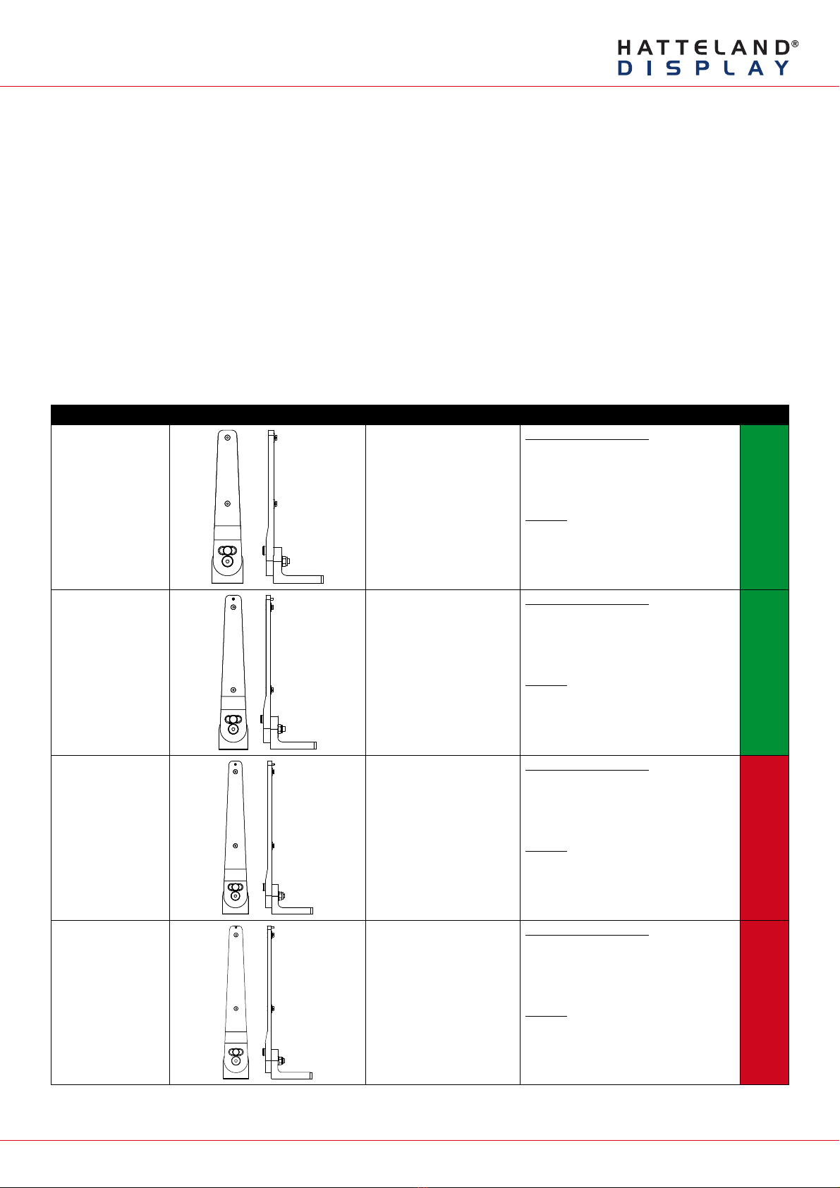
Two versions of bracket exists, please review the table below to identify your unit model and bracket type. Brackets
that are currently sold/delivered are marked with green color. Those which are obsolete (and replaced by newer type
of bracket) are shown in red color. The two bracket types exists due to slight variation in manufacturing regarding the
unit’s mounting holes (key hole) that exist with either “single key hole” or “double key hole”.
Bracket Arms are clearly marked with Typenumber label so you can identify which version you have (BRD or TMB).
Note: If you ordered a unit with mounting bracket from factory, the corresponding matching bracket has been already
been chosen to ensure correct fitting. If you order brackets separately at a later date, you should study the table
below carefully as well as review the type of key hole your Display or Panel Computer units has. If unsure, please
contact Hatteland Display for support in choosing the correct bracket version (BRD or TMB).
Table last updated 09 Feb 2015. Throughout 2015 the BRD (HW00) versions will be phased out of production and
only TMB (HW01) versions will remain available for manufactured units.
Typenumber Illustration Fits unit model Notes Status
HD 12BRD SX1-A1 HD 12T21 MMD-xxx-Fxxx
HD 12T21 STD-xxx-Fxxx
HD 12T21 MMC-xxx-xxxx
“HW blank” and “HW00”:
Sold since 2014. Fits Single Key Hole
Chassis only. Will be replaced by
“HW01”, when HW00 is out of stock.
“HW01”:
For Double Key Hole Chassis, use
HD TMB SX1-A1 (see next page).
HD 15BRD SX1-A1 HD 15T21 MMD-xxx-Fxxx
HD 15T21 STD-xxx-Fxxx
HD 15T21 MMC-xxx-xxxx
“HW blank” and “HW00”:
Sold since January 2013, fits only Single
Key Hole Chassis. Will be replaced by
“HW01”, when HW00 is out of stock.
“HW01”:
For Double Key Hole Chassis, use
HD TMB SX1-A1 (see next page).
HD 17BRD SX1-A1 HD 17T21 MMD-xxx-Fxxx
HD 17T21 STD-xxx-Fxxx
HD 17T21 MxC-xxx-xxxx
“HW blank” and “HW00”:
Sold since June 2012, fits only Single
Key Hole Chassis. Obsolete, replaced by
“HW01”.
“HW01”:
For Double Key Hole Chassis, use
HD TMB SX1-B1 (see next page).
HD 19BRD SX1-A1 HD 19T21 MMD-xxx-Fxxx
HD 19T21 STD-xxx-Fxxx
HD 19T21 MxC-xxx-xxxx
“HW blank” and “HW00”:
Sold since March 2012, fits only Single
Key Hole Chassis. Obsolete, replaced by
“HW01”.
“HW01”:
For Double Key Hole Chassis, use
HD TMB SX1-B1 (see next page).
Page 2 of 7
IND100148-7 - Rev 06 - 16 Feb 2015 - Created by: 363
Hatteland Display AS, Stokkastrandvegen 87B, N-5578 Nedre Vats, Norway
Tel: (+47) 4814 2200 - mail@hatteland-display.com - www.hatteland-display.com
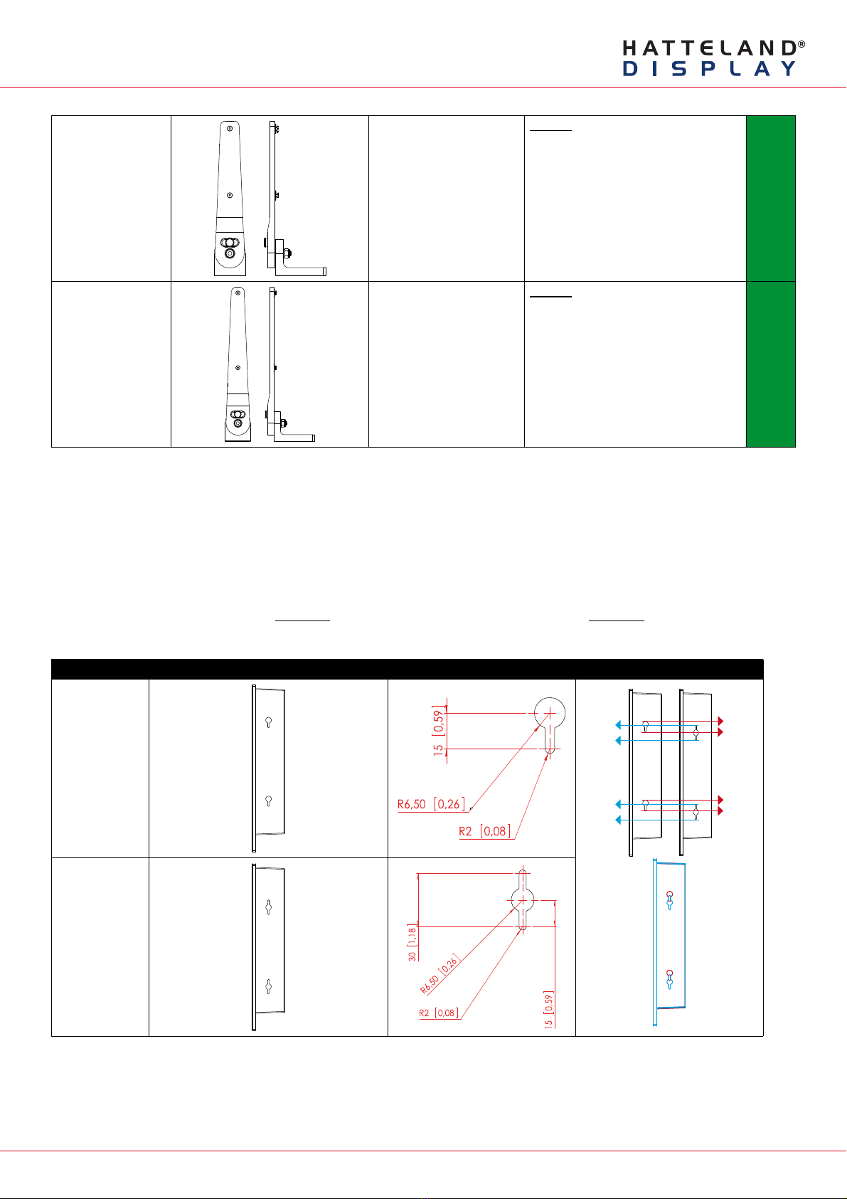
HD TMB-SX1-A1 HD 12T21 MMD-xxx-Fxxx
HD 12T21 STD-xxx-Fxxx
HD 12T21 MMC-xxx-xxxx
HD 15T21 MMD-xxx-Fxxx
HD 15T21 STD-xxx-Fxxx
HD 15T21 MMC-xxx-xxxx
“HW01”:
Sold since April 2012.
Fits Double Key Hole Chassis only.
HD TMB-SX1-B1 HD 17T21 MMD-xxx-Fxxx
HD 17T21 STD-xxx-Fxxx
HD 17T21 MxC-xxx-xxxx
HD 19T21 MMD-xxx-Fxxx
HD 19T21 STD-xxx-Fxxx
HD 19T21 MxC-xxx-xxxx
“HW01”:
Sold since May 2012.
Fits Double Key Hole Chassis only.
* Note: Reference to HWxx (Hardware Code) can be identified by number of digits in a Display or Panel
Computer serial number. Each HWcode upgrade will add 10000 in value to exisiting Serial Number counting.
Single Key Hole vs Double Key Hole
Our Display or Panel Computer units may have Single Key Hole, whilst others have Double Key Hole present in the
chassis sides. This is due to slight variation in initial production vs Mass Production throughout 2012-2015. It should
be noted that Single Key hole units does not support ceiling mount. Double Key Hole supports ceiling mount of unit.
Single or Double Key Hole can be identified as follows:
Key Hole Type Key Hole Location (seen from both sides) Key Hole Dimensions Key Hole Difference
Single
Double

Page 3 of 7
IND100148-7 - Rev 06 - 16 Feb 2015 - Created by: 363
Hatteland Display AS, Stokkastrandvegen 87B, N-5578 Nedre Vats, Norway
Tel: (+47) 4814 2200 - mail@hatteland-display.com - www.hatteland-display.com
Important to know about LEFT and RIGHT brackets
Throughout the following installation procedure for both BRD and TMB brackets, it is important to understand the
difference between LEFT and RIGHT brackets. The Display and Panel Computer chassis are not 100% square
boxed, but are slightly designed with a minor narrow angled chassis towards the rear (FIG1) to allow easier “drop-
in” of units into consoles. Likewise to get a correct footprint placement of the brackets, both brackets feature a slight
angled design on the oval circled cut shaped block to compensate for this (FIG2) making LEFT and RIGHT bracket
slightly different and naturally has to be correctly mounted.
Please ensure that LEFT and RIGHT brackets are as indicated in FIG4, and not as shown in FIG3 below.
FIG 1
Red Line straight up
Green Line indicates slight angled design of chassis
FIG 2
Location of angled block,
and seen straight from top showing slight angle
LEFT BRACKET RIGHT BRACKET
FIG 3 - Seen from under bracket base
Wrong mounting of LEFT / RIGHT Brackets
Indicating footprint is incorrect
FIG 4- Seen from under bracket base
Correct mounting of LEFT / RIGHT Brackets
Indicating footprint is correct

Page 4 of 7
IND100148-7 - Rev 06 - 16 Feb 2015 - Created by: 363
Hatteland Display AS, Stokkastrandvegen 87B, N-5578 Nedre Vats, Norway
Tel: (+47) 4814 2200 - mail@hatteland-display.com - www.hatteland-display.com
Installation Procedure - BRD Versions
Procedure suitable for: Display (MMD/STD) and Panel Computer (MMC) Series X product ranges.
You need:
- M4, M5 Unbrako® Hex Key tool (not included with delivery).
- Fasteners (6 pcs M6) for mounting complete unit onto table or desktop location (not included with delivery).
- 1 pcs of HD xxBRD SX1-A1 Mounting Bracket Kit, where xx=15, 17 or 19 inch.
Attention: A suitable pre-drilled location and knowledge of measurements for both main unit and
brackets/tilting functionality should be prepared and checked prior to mounting. Please disconnect
ALL cables before proceeding. Please review User Manual or visit www.hatteland-display.com for
Technical Drawings regarding measurements for both main unit and Mounting Brackets.
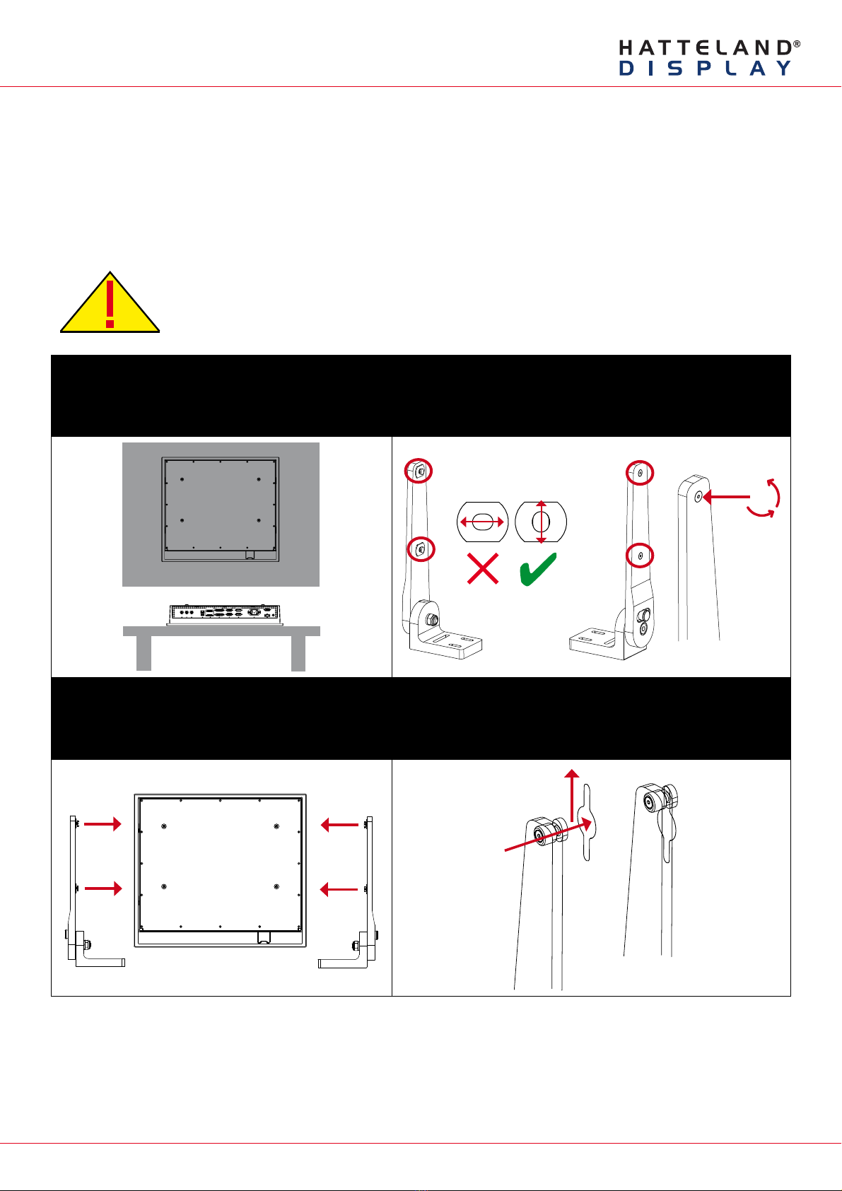
▼1: Place the unit on a dry, flat, clean, soft surface (i.e.
table) with the glass front facing down as illustrated.
Connector area should be facing downwards from you.
▼2: Inspect the inner side of both brackets and especially the
orientation of the Key Hole Plug (4 pcs). They should be shaped
as an standing “egg” to ensure proper fitting in the Key Hole of
unit (FIG1). Note: You may have to loose the fastening screw (M5)
(FIG2) if the Key Hole Plug can not be turned by hand.
Seen from
above
Connector Area
Wrong Correct Adjust
FIG2
FIG1
▼3: Verify that the Key Hole Set Screw (M4) is aligned
with the bracket surface (FIG1). If this screw appear too
far out (FIG2), proper fitting into the Key Hole can not be
completed. Turn screw clockwise or anti-clockwise (FIG3)
to adjust the position.
▼4: Notice the indication of LEFT and RIGHT. The mounting
bracket (2 pcs) is marked with respective stickers “L” and “R” from
factory. Please make sure that LEFT bracket is positioned on LEFT
side and RIGHT bracket is positioned on the RIGHT side as shown
below.
Wrong Correct Adjust
FIG1 FIG3FIG2
Bracket Surface
LEFT RIGHT

Page 5 of 7
IND100148-7 - Rev 06 - 16 Feb 2015 - Created by: 363
Hatteland Display AS, Stokkastrandvegen 87B, N-5578 Nedre Vats, Norway
Tel: (+47) 4814 2200 - mail@hatteland-display.com - www.hatteland-display.com
▼5: Ensure that both Key Hole Plugs slide into the Key Holes and goes to the bottom position (FIG1 and FIG2). If they appear
too tight, you may loose the Key Hole Plug screw a few turns and re-try (see previous step 2). FIG3 shows Key Hole Plug
correctly into Key Hole and both brackets in place.
FIG1
FIG2 FIG3
FIG3
▼6: Tighten Key Hole Screw firmly on each side and
make sure the brackets are properly mounted and
aligned to the main chassis of unit. Verify with your
hands that both brackets are firmly attached.
▼7: While unit is lying flat on table, check the Tilting Lock Pin
position. These can be pulled out by hand, turned 90° (FIG1) and
turned back 90° until the Lock Pin automatically clicks into place by a
spring (FIG2).
FIG1
FIG2
Locked Unlocked
▼8: You may now mount the unit onto your desired location. It is advised that you unlock the Lock Pin (as shown in step 7), tilt
the unit 90 degrees backwards (FIG1) and properly fasten the bracket base into location (FIG2). NB! Be careful not to break
or scratch the edge of the front glass! Then repeat step 7 again until your desired tilting position has been achieved and you
have verified that the Lock Pin are in locking position and the unit is firmly attached and does not appear loose (FIG3).
Unlock, tilt and lock
FIG1 FIG2 Top View
Use appropriate fasteners
6 pcs x M6 needed
FIG3
Re-check Lock Pins!
Single Key hole units does not support ceiling mount.
Page 6 of 7
IND100148-7 - Rev 06 - 16 Feb 2015 - Created by: 363
Hatteland Display AS, Stokkastrandvegen 87B, N-5578 Nedre Vats, Norway
Tel: (+47) 4814 2200 - mail@hatteland-display.com - www.hatteland-display.com
Installation Procedure - TMB Versions
Procedure suitable for: Display (MMD/STD) and Panel Computer (MMC) Series X product ranges.
You need:
- M4 Unbrako® Hex Key tool (not included with delivery).
- Fasteners (6 pcs M6) for mounting complete unit onto table or desktop location (not included with delivery).
- 1 pcs of HD TMB SX1-A1 Mounting Bracket Kit (for 12 and 15 inch)
- or 1 pcs of HD TMB SX1-B1 Mounting Bracket Kit (for 17 and 19 inch)
Attention: A suitable pre-drilled location and knowledge of measurements for both main unit and
brackets/tilting functionality should be prepared and checked prior to mounting. Please disconnect
ALL cables before proceeding. Please review User Manual or visit www.hatteland-display.com for
Technical Drawings regarding measurements for both main unit and Mounting Brackets.
▼1: Place the unit on a dry, flat, clean, soft surface (i.e.
table) with the glass front facing down as illustrated.
Connector area should be facing downwards from you.
▼2: Inspect the inner side of both brackets and especially the
orientation of the Key Hole Plug (4 pcs). They should be shaped
as an standing “egg” to ensure proper fitting in the Key Hole of
unit (FIG1). Note: You may have to loose the fastening screw (M5)
(FIG2) if the Key Hole Plug can not be turned by hand.
Seen from
above
Connector Area
Wrong Correct Adjust
FIG2
FIG1
▼3: Notice the indication of LEFT and RIGHT. The
mounting bracket (2 pcs) is marked with respective
stickers “L” and “R” from factory. Please make sure that
LEFT bracket is positioned on LEFT side and RIGHT
bracket is positioned on the RIGHT side as shown below.
▼4: Ensure that both Key Hole Plugs slide into the Key Holes and
goes to the upper position (FIG1 and FIG2). If they appear too tight,
you may loose the Key Hole Plug screw a few turns and re-try (see
previous step 2).
LEFT RIGHT FIG1
FIG2
Page 7 of 7
IND100148-7 - Rev 06 - 16 Feb 2015 - Created by: 363
Hatteland Display AS, Stokkastrandvegen 87B, N-5578 Nedre Vats, Norway
Tel: (+47) 4814 2200 - mail@hatteland-display.com - www.hatteland-display.com
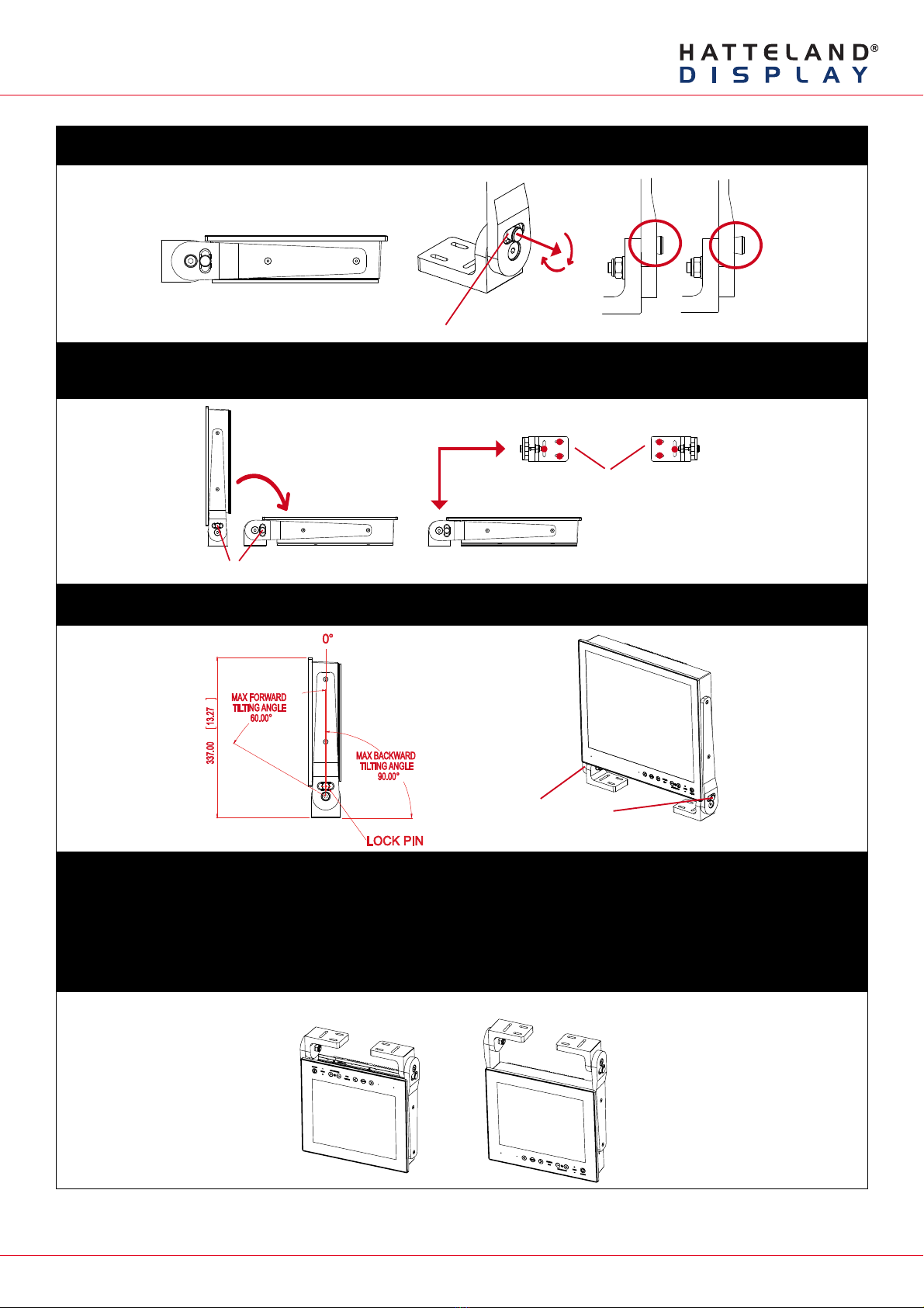
▼5: While unit is lying flat on table, check the Tilting Lock Pin position. These can be pulled out by hand, turned 90° (FIG1) and
turned back 90° until the Lock Pin automatically clicks into place by a spring (FIG2).
FIG1
FIG2
Locked Unlocked
Glass Facing Up
▼6: You may now mount the unit onto your desired location. It is advised that you unlock the Lock Pin (as shown in step 5), tilt
the unit 90 degrees backwards (FIG1) and properly fasten the bracket base into location (FIG2). NB! Be careful not to break
or scratch the edge of the front glass!
Unlock, tilt and lock
FIG1 FIG2 Top View
Use appropriate fasteners
6 pcs x M6 needed
▼7: Max Forward and Backward angle shown below (FIG1). When your desired tilting position has been achieved, you need to
verify that the Lock Pin are in locking position and the unit is firmly attached and does not appear loose (FIG2).
FIG2
Re-check Lock Pins!
FIG1
▼8: Depending on installation needs, you may mount the complete unit in ceiling in two different ways.
Normal Position: User Controls will be upside down, cables go straight up. You may configure Glass Display Control™(GDC)
LED symbols to show or not, since symbols will be seen upside down.
Review http://www.hatteland-display.com/inb100018-4.php (“Glass Display Control™ (GDC) LED & Button operations” section).
Swapped Position: User Controls readable, cables has to bend up or go straight down, Left and Right Bracket needs to be
swapped, indicating Left Bracket on Right Side, and RIght Bracket on Left Side to ensure proper fitting and to avoid wrong
footprint of the mounting holes of the bracket base (reference to “Important to know about LEFT and RIGHT brackets”).
Normal Position Swapped Position
This manual suits for next models
5
Table of contents
Popular TV Mount manuals by other brands

MORryde
MORryde TV1-003H installation instructions

Royal Mounts
Royal Mounts ROY5603B user manual

FONESTAR
FONESTAR STTEL-44N instruction manual

Tecnosystemi
Tecnosystemi smart clima DONATELLO SD user manual

Dynex
Dynex DX-TVM111 Assembly guide

Sony
Sony KDL22L5000 - BRAVIA L Series Additional information for Using


