manuals.online logo
Brands
  1. Home
  2. •
  3. Brands
  4. •
  5. HAUTAU
  6. •
  7. DC Drive
  8. •
  9. HAUTAU HS User manual

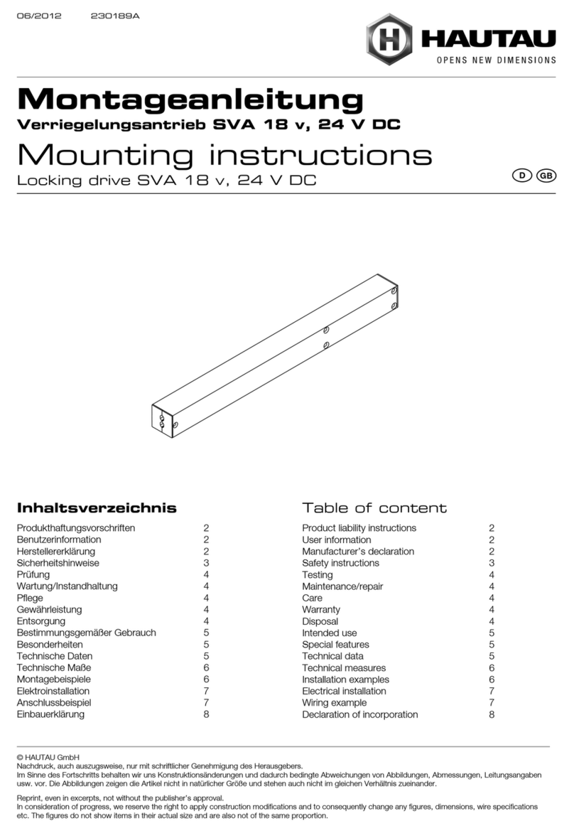
HAUTAU HS User manual

HAUTAU
LIFT&SLIDE HARDWARE
MOUNTING INSTRUCTIONS
HS comfort drive
Timber, Timber-Alu covered
HAUTAU, a MACO Group company
Only for use by certied specialists!
TIMBERALU
2
Table of content
Important safety instructions �������������������������������������������������������������������������������������������������������������������������������������������������� 4 - 7
Abbreviations ��������������������������������������������������������������������������������������������������������������������������������������������������������������������������������������� 8
Warranty ������������������������������������������������������������������������������������������������������������������������������������������������������������������������������������������������ 8
Disposal �������������������������������������������������������������������������������������������������������������������������������������������������������������������������������������������������� 8
EC declaration of incorporation ����������������������������������������������������������������������������������������������������������������������������������������������������� 9
Operation ��������������������������������������������������������������������������������������������������������������������������������������������������������������������������������������������� 10
Explanation of terms ������������������������������������������������������������������������������������������������������������������������������������������������������������������������ 11
Manual release/locking in case of power failure
in the closed state ������������������������������������������������������������������������������������������������������������������������������������������������������������������ 12
in the open state �������������������������������������������������������������������������������������������������������������������������������������������������������������������� 13
Parts overview ���������������������������������������������������������������������������������������������������������������������������������������������������������������������������� 14 - 15
Preparatory actions ������������������������������������������������������������������������������������������������������������������������������������������������������������������������� 16
Preparation of electrical connection ������������������������������������������������������������������������������������������������������������������������������������������ 16
Cut-outs for circuit board ���������������������������������������������������������������������������������������������������������������������������������������������������������������� 17
Cut-outs for drive unit �������������������������������������������������������������������������������������������������������������������������������������������������������������������� 18
Locking, control- and current transition ����������������������������������������������������������������������������������������������������������������������������������� 19
Cut-outs for lock case, li-drive and hook-box ���������������������������������������������������������������������������������������������������������������������� 20
Positioning of the drive pin ������������������������������������������������������������������������������������������������������������������������������������������������������������ 21
Borings for manual unlocking handle ���������������������������������������������������������������������������������������������������������������������������������������� 22
Mounting driving unit ��������������������������������������������������������������������������������������������������������������������������������������������������������������������� 23
Mounting of deection tooth belt ���������������������������������������������������������������������������������������������������������������������������������������������� 24
Mounting of cover prole �������������������������������������������������������������������������������������������������������������������������������������������������������������� 25
Mounting of tooth belt ������������������������������������������������������������������������������������������������������������������������������������������������������������������� 26
Connect drive-pin with toothbelt ������������������������������������������������������������������������������������������������������������������������������������������������ 27
Mounting of guide track ����������������������������������������������������������������������������������������������������������������������������������������������������������������� 28
Mounting circuit board ������������������������������������������������������������������������������������������������������������������������������������������������������������������� 29
Mounting of magnets ��������������������������������������������������������������������������������������������������������������������������������������������������������������������� 30
Mounting of the support plates for cover electronics ��������������������������������������������������������������������������������������������������������� 30
Possibilities of cable routing ���������������������������������������������������������������������������������������������������������������������������������������������������������� 31
Mounting of current transition and control keypad ������������������������������������������������������������������������������������������������������������� 32
Mounting of hook locking part ���������������������������������������������������������������������������������������������������������������������������������������������������� 33
Mounting of rollers �������������������������������������������������������������������������������������������������������������������������������������������������������������������������� 34
3
Mounting of gear ������������������������������������������������������������������������������������������������������������������������������������������������������������������������������ 35
Lubrication of hook drive gears and striker plates ���������������������������������������������������������������������������������������������������������������� 36
Mounting of drive support ������������������������������������������������������������������������������������������������������������������������������������������������������������ 36
Hooking the sash ������������������������������������������������������������������������������������������������������������������������������������������������������������������������������ 37
Adjustment of tension of tooth belt ������������������������������������������������������������������������������������������������������������������������������������������ 38
Cover prole cut to length ������������������������������������������������������������������������������������������������������������������������������������������������������������� 39
Mounting cover prole for tooth belt ��������������������������������������������������������������������������������������������������������������������������������������� 40
Coupling of li drive �������������������������������������������������������������������������������������������������������������������������������������������������������������������������� 41
Electrical connection ��������������������������������������������������������������������������������������������������������������������������������������������������������������� 42 - 48
Check/Adjust DIP switch ���������������������������������������������������������������������������������������������������������������������������������������������������������������� 49
Triggering of ‘Full-Init’ and ‘Home-Init’ ������������������������������������������������������������������������������������������������������������������������������������� 50
First start up (‘Full-Init’) ���������������������������������������������������������������������������������������������������������������������������������������������������������� 50 - 51
Standard operation �������������������������������������������������������������������������������������������������������������������������������������������������������������������������� 52
Teach-in run (‘Home-Init’) �������������������������������������������������������������������������������������������������������������������������������������������������������������� 53
Safety function check ‘reversing’ ������������������������������������������������������������������������������������������������������������������������������������������������ 54
Mounting of the cover electronics ���������������������������������������������������������������������������������������������������������������������������������������������� 55
Mounting of the cover for manual release/locking �������������������������������������������������������������������������������������������������������������� 55
Fault elimination �������������������������������������������������������������������������������������������������������������������������������������������������������������������������������� 56
Maintenance/repair ������������������������������������������������������������������������������������������������������������������������������������������������������������������������� 56
Care �������������������������������������������������������������������������������������������������������������������������������������������������������������������������������������������������������� 57
Technical specication ������������������������������������������������������������������������������������������������������������������������������������������������������������ 58 - 59
Mounting and Installation IR-Light curtain �������������������������������������������������������������������������������������������������������������������� 60 - 65
Installation IR-Presence sensor ��������������������������������������������������������������������������������������������������������������������������������������������������� 66
Connection of 1-button control pushbutton ������������������������������������������������������������������������������������������������������������������ 67 - 70
Table of content (continuation)
4
The safety of personnel requires that the following instructions be observed� Incorrect installation can lead to
severe injury!
Declaration of Conformity/state of the art
The drive has been constructed and tested in conformity with all applicable European directives�
A corresponding declaration of incorporation is available� You may not operate the equipment unless a
declaration of conformity is available for the overall system�
The drive complies with the state of the art and requires qualied personnel for installation, maintenance, etc.
Personnel
Professional execution of electrical connection has to be entrusted to trained electricians! (as specied e. g. in
DIN VDE 1000-10)�
The mounting of the drive has to be performed by personnel, which has been instructed acc� to the state of
the art and acc� to recognised rules of technology�
Intended use
› A power-operated (li and) slide window with horizontally slidable sashes is used as a side entrance and side
exit between two separate locations, in order to link interior and exterior�
› Use of the HS/S comfort drive only for sashes with a weight of max� 300 kg (integrated anti-trap
protection)�
Depending on the risk assessment, for sash weights of 300 ... 440 kg additional safety devices, such
as light curtain, presence sensor or key switch have to be installed.
› The complete element has to be mounted perpendicularly�
› For maintenance purposes all components of the window element have to be freely accessible�
› In closed position, the sash is lowered and locked by means of locking hooks�
› The li and slide window cannot be used as emergency door for re protection, smoke protection or as
escape door�
› For version with li drive: in case of power failure it is possible to manually li, lower and slide the movable
sash with a plug-in handle� This enables a release/locking in open/closed position�
Select the required mounting material in accordance with the structure and the respective load and use
additional mounting material if necessary� Any included mounting material will only correspond to parts of
the required material�
WARNING!
Important safety instructions
5
Any individual applications or modications of the drive which are not in compliance with intended use are
explicitly prohibited� We shall not be liable for any damage to personnel or material resulting from
non-compliance with this provision�
Pay attention to the ‘Guidelines/advice on the product and on liability’ (VHBH) of the Quality Assurance
Association: Locks and Hardware.
Storing documents/instructions
Store these instructions for future reference and maintenance� Make these installation instructions available
to the end user and provide instructions�
Installation und operation
Prior to installation: Test window and safety elements. The physical integrity and smooth operation of the
window must be ensured�
All works (installation, adjustment etc�) have to be done in currentless condition�
Before installing the drive, it must be veried that the drive‘s temperature range has been adapted to its
operating environment�
To fasten the parts, use screws with sucient length, so that they can reach into the steel reinforcement in
case of PVC proles.
No other persons are allowed in the vicinity of the drive when a key switch with o presetting (DEAD-MAN
switch) is actuated�
WARNING: Never connect the drive/control keypad to 230 V of voltage!
The drive may only be operated at very low safety voltage� Otherwise, there is danger to life!
CAUTION: Failure to follow the work steps will destroy the drive� Improper handling endangers the
material. Do not allow any liquid to enter the interior of the device! No objects or dirt shall be le on
the running rail�
Risk of crushing and pinching!
To avoid misuse, a risk assessment acc� to Machinery Directive 2006/42/EC is required at the
installation site� Protective measures are to be applied according to EN 60335-2-103/2016-05�
Dependi ng on the risk assessment, for sash weights of 300 ��� 440 kg additional safety devices,
such as light curtain, presence sensor or key switch have to be installed�
Important safety instructions (continuation)
6
The drive opens and closes windows automatically�
It is stopped by overload cuto. However, the compressive force is sucient to crush ngers if you
act carelessly�
Do not reach into the window rebate or the drive while the drive is running!
This device may be used by children age 8 and older as well as all persons without limited physical,
sensory or mental abilities or lack of experience and knowledge provided they act under supervision
or have received prior instructions on the safe use of the device and any hazards resulting from
using the device�
Children are not allowed to play with the device�
Cleaning and user maintenance must not be carried out by children without supervision�
Make sure there are no people or objects in the movement area of the sliding sash�
If the sliding sash element does not have additional safety devices, such as light curtain or presence
sensor, you have to operate the drive only when there is visual contact with the door�
Observe the run of the sash until the door has reached the end position�
Do not pass through remote-controlled doors until the door has stopped�
Make sure that remote controls do not come into the hands of children and are only used by people
who are familiar with the operation of the remotecontrolled door�
When operating with a remote control, there must be visual contact with the door if it does not have
an additional safety device (light curtain, presence sensor)�
Please note that a button can be accidentally pressed on the hand-held transmitter (for example in
the pocket/handbag) and this can lead to an unintended door movement�
Make sure that there are no persons or objects in the movement area of the door when teaching-in
the door�
Testing
When installation is complete and aer any changes to the system, check all functions by a trial run.
Note:
If spare parts or extension components are required or desired, use only original spare parts�
No liability will be accepted and no guarantee nor service is granted if products made by outside
manufacturers are used�
Reliable operation without any damage and hazards requires that installation / setup be made
carefully in accordance with these instructions�
Important safety instructions (continuation)
7
Maintenance/repair
The power supply to the device must be interrupted for the duration of any cleaning or other types of
maintenance operations�
Windows and drives must be checked for physical integrity at least once a year�
Free the drives from any contamination. Check the tightness of xing and clamping screws. The tension of
tooth belt has to be checked every year and the tooth belt has to be retensioned, if necessary (refer to section
‘Adjustment of tension of tooth belt’)� The parts to be checked and the items to be maintained can be found in
the maintenance check list (www�hautau�de)� The end customer can perform all of the steps described�
If deviating from the instruction steps, limitation of warranty claims must be expected�
Test the drive by trial run� Defective drives must be repaired at our factory� You may only use original spare
parts�
The readiness for operation has to be checked regularly�
Care
Check all devices and cable connections for external damage and dirt� The operability of the control keypad
must not be aected by, for example, structural measures or stored goods.
Use a so, slightly dampened cloth to clean the housing components and the control keypad. To prevent
damage to the surfaces, do not use any caustic chemicals, abrasive cleaners or agents containing solvents for
cleaning� Provide the drive with durable protection against water and dirt�
Important safety instructions (continuation)
8
Abbreviations
HS / S Li & Slide / Slide ...
LH Length of li drive
RAB Outer frame width
Warranty
The drive is subject to HAUTAU’s Terms and Conditions (TC) (Internet: www.HAUTAU.de).
Disposal
The crossed-out wheeled bin symbol indicates that you must not dispose of this electrical appliance
or electronic device in the household waste at the end of its service life�
You can return it to free collection points for old electrical appliances in your area or to other centres
where they accept old appliances for recycling� Contact your local council for addresses of collection
points and centres� If the electrical appliance or electronic device contains personal data, you
yourself are responsible for erasing data before you return it. You will nd more information online
at www�weeelogic�com or other websites on the WEEE Directive�
9
10
*
*
*
1
1
1
1
1
2
2
1
1
1
2
Operation
Green lights during movement of the
li / sliding drive
During Init run Yellow is ashing; aer
nishing the Init run, both LEDs are o
Yellow lights in case of fault
Closing
Opening
*) for HS comfort drive, only
11
Explanation of terms
Le version
(sliding sash opening from the le to the right,
drive module on the right)
Right version
(sliding sash opening from the right to the le,
drive module on the le)
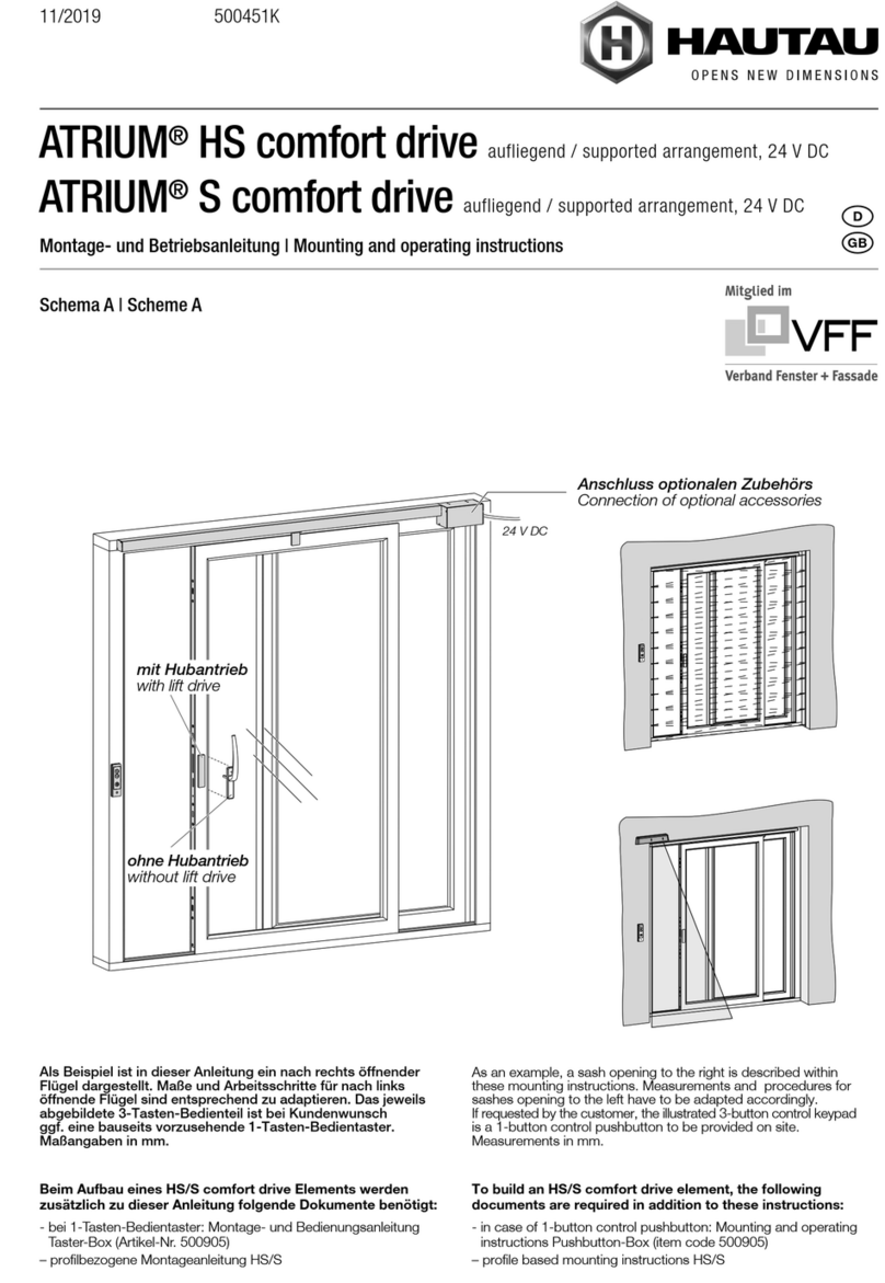
As an example, a sash opening to the right is described within these mounting instructions�
Measurements and procedures for sashes opening to the le have to be adapted accordingly.
Measurements in mm�
12
EIN
ON
AUS
OFF
2.2
2.1
5.1
ca.135°
5.2
6.1
6.2
ca.135°
7.3
7.3 7.2
A
B
7.2
7.1
3.1
4.2
4.1
3.2
1. Fuse box
ATTENTION: Do not release the handle, guide the handle in the locked position,
because it turns arround quickly due to the sash weight, thus could cause heavy injuries
(see point 5 and 6).
1. Switch o electricity primary sided before the power supply unit.
2� Remove the cap�
3. Insert the manual unlocking-handle into the gear and move it a little to le and right, to release the gear.
4. Install the unlocking key and rotate it to the glazing side until you hear a closure sound.
5. Now, you can li the sash by means of a release handle, move it to the desired position and move it into
the lowered position�
Locking
6. Insert the manual release handle back into the drive gear spindle and li the door (6.1, 6.2). Slide the door
shut and lock it�
7. Bring the coupling pin of the li drive (A) in matching position to the drill hole of the drive rod (B). In order
to couple li drive and drive rod, turn the unlocking key towards the frame side (7.2).
WARNING:
If the manual unlocking-handle will not be pulled o before electrical start-up, this can lead to
severe injuries!
Manual release/locking in case of power failure in
the closed state
13
2.2
2.1
1.
3.1
3.2
4.2
4.1
7.3
7.1
7.2
5.1
ca.135°
5.2
6.1
6.2
ca.135°
7.3 7.2
A
B
EIN
ON
AUS
OFF
2.2
2.1
5.1
ca.135°
5.2
6.1
6.2
ca.135°
7.3
7.3 7.2
A
B
7.2
7.1
3.1
4.2
4.1
3.2
1.
ATTENTION: Do not release the handle, guide the handle in the locked position,
because it turns arround quickly due to the sash weight, thus could cause heavy injuries
(see point 5 and 6).
1. Switch o electricity primary sided before the power supply unit.
2� Remove the cap�
3. Insert the manual unlocking-handle into the gear and move it a little to le and right, to release the gear.
4. Install the unlocking key and rotate it to the glazing side until you hear a closure sound.
5. Now, you can li the sash by means of a release handle, move it to the desired position and move it into
the lowered position�
Locking
6. Insert the manual release handle back into the drive gear spindle and li the door (6.1, 6.2). Slide the door
shut and lock it�
7. Bring the coupling pin of the li drive (A) in matching position to the drill hole of the drive rod (B). In order
to couple li drive and drive rod, turn the unlocking key towards the frame side (7.2).
WARNING:
If the manual unlocking-handle will not be pulled o before electrical start-up, this can lead to
severe injuries!
Manual release/locking in case of power failure in
the open state
Fuse box
14
1
7
5
5
7
5
6
7
9
8
3
11 2
4
14
13
15 25
16
20
21
21
19
17
10
22
23
24
Holz*
12
5
3
4
13
18
16 20
19
15
**
Parts overview
Example: le version (sliding sash opening from the le to the right - view from inside)
optional
*) not included within scope of delivery
**) in case of 1-button control pushbutton on site, only
Timber*
15
Parts overview (continuation)
1Drive unit
2Circuit board
3Power pack
4Cover power pack
5Upper guide unit with accesoires
6 Deection tooth belt
7Cover support
8 Cover prole
9Tooth belt
10 Clamping plates drive unit bootom
11 Cover electronics timber
12 Support plate and magnet(s)
13 Cable for li drive
14 Cable for control keypad
15 Control keypad
16 Cover for manual release / locking (in connection with li drive)
17 Li drive
18 Current transition
19 Contact delivery (in connection with lt drive)
20 Emergency release set (drive handle and universal key) (in connection with li drive)
21 Hook locking part
22 Key switch
23 Connection box HS/S comfort drive
24 WLAN box
25 Pushbutton-Box
16
~ 1050
320
30
18
2,9 x ...
Torx T10/T20 410
+
› All screwings have to reach suciently into the timber.
› Check parts for completeness�
› Required milling must be done in the workshop�
› Tools to be used (these have to be provided acc. to instructions):
Preparatory actions
Preparation of electrical connection
Example: le version (sliding sash opening from the le to the right - view from inside)
Connecting cable with 1,5 mm² cross-section
Power Pack
Drive unit
later position of the
control keypad
empty conduits Ø 16 mm for
cable routing within the reveal
17
R8
40
56
46
==
18
94
10
84
21
26
40
46
10
22
75
300
317
75
656
50
10
16
345
339
21
84
46
75
300
657
17
50
345
50
Ø12
R8
R8
R8
R8
R8
Ø12
300
340
345
317
50 4
16
74
22
50
75
R8
R8
R8
Ø12
X
B-B
C-C
D-D
A-A
BA
DD
CC
X
BA
Cut-outs for circuit board
18
Y
Y
E
G
G
F
F
G-G
F-F
EE-E
120
16
R8
120
16 16
12,5
22
25
6
169
175
12,515,5
82
50
92
192
R8
R8
Ø9
Ø9
L= RAB/2+240
24
Ø9
12,5
25
22
27,5
54
42
43
12
43
12
86
50
82
66,5
74
L= RAB/2+116
==
Cut-outs for drive unit
19
B ± 1,5
A ± 1,5
C ± 1,5
A; B; C;
A; B; C;
DD
16
120
16
16
120
16
39
40
12
12
10
3
120
16
16
16
Ø16
Ø12
R8
R8
Ø16
GM-95
R8
C
BB
17
AB
145 733
733145
Gr. 4
Gr. 5
C
1613
2045
D
1794Gr. 4
Gr. 5 2342
D
12
Ø12
10
64
32
13
3
12
40
16
16
12
Locking, control- and current transition
hook gear A B C
size 4 145 733 1613
size 5 145 733 2045
hook gear size 4 position B is optional
hook gear D
size 4 1794
size 5 2342
20
B
B
46
22
63
254230
230
115115254
1000
1010
X
X
A
B
X
125
Gr. 4
Gr. 5 292
80
22
28
22
22
8
50
C
C
C
C
C
A
Y
B
A
166
Gr. 4
Gr. 5 166
754
754
1634
2066
BC
46 56300 kg
Y
Cut-outs for lock case
A
, Cut-outs for li-drive
B
,
Cut-outs for hook-box
C
X
size 4 125
size 5 292
hook gear A B C
size 4 166 754 1634
size 5 166 754 2066
hook gear size 4 position B is optional
Y
300 kg 46 56

This manual suits for next models

1

Other HAUTAU DC Drive manuals

HAUTAU ATRIUM HS Service manual

HAUTAU

HAUTAU ATRIUM HS Service manual

HAUTAU SKA 20-118 User manual

HAUTAU

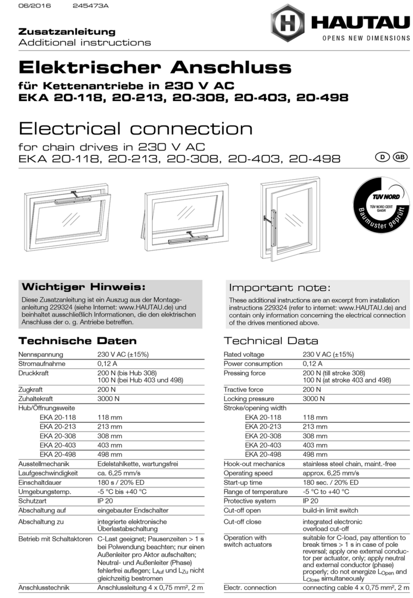
HAUTAU SKA 20-118 User manual

HAUTAU PRIMAT-E kompakt 195 User manual

HAUTAU

HAUTAU PRIMAT-E kompakt 195 User manual

HAUTAU EM 101 User manual

HAUTAU

HAUTAU EM 101 User manual

HAUTAU EM 100 Service manual

HAUTAU

HAUTAU EM 100 Service manual

HAUTAU EA 500 N Service manual

HAUTAU

HAUTAU EA 500 N Service manual

HAUTAU EKA 20-118 Operating manual

HAUTAU

HAUTAU EKA 20-118 Operating manual

HAUTAU PRIMAT-E kompakt 300 User manual

HAUTAU

HAUTAU PRIMAT-E kompakt 300 User manual

HAUTAU SKA 30/2-200 User manual

HAUTAU

HAUTAU SKA 30/2-200 User manual

HAUTAU EM3 User manual

HAUTAU

HAUTAU EM3 User manual

HAUTAU SA Series Service manual

HAUTAU

HAUTAU SA Series Service manual

HAUTAU SKA 20 User manual

HAUTAU

HAUTAU SKA 20 User manual

HAUTAU EKA 45-400 Service manual

HAUTAU

HAUTAU EKA 45-400 Service manual

HAUTAU EA 500-300 Service manual

HAUTAU

HAUTAU EA 500-300 Service manual

HAUTAU SKA 30 Service manual

HAUTAU

HAUTAU SKA 30 Service manual

HAUTAU PRIMAT-E Kompakt 190 User manual

HAUTAU

HAUTAU PRIMAT-E Kompakt 190 User manual

HAUTAU EM 2 User manual

HAUTAU

HAUTAU EM 2 User manual

HAUTAU SM 100 Service manual

HAUTAU

HAUTAU SM 100 Service manual

HAUTAU SM 2 User manual

HAUTAU

HAUTAU SM 2 User manual

HAUTAU 20-118 User manual

HAUTAU

HAUTAU 20-118 User manual

HAUTAU SVA 18 v User manual

HAUTAU

HAUTAU SVA 18 v User manual

HAUTAU SM 101 User manual

HAUTAU

HAUTAU SM 101 User manual

Popular DC Drive manuals by other brands

GFA ELEKTROMAT SE 9.24-25,40 Ex installation instructions

GFA

GFA ELEKTROMAT SE 9.24-25,40 Ex installation instructions

Festo DGC-HD Series Instructions & Operating

Festo

Festo DGC-HD Series Instructions & Operating

SIEB & MEYER SD2 Hardware description

SIEB & MEYER

SIEB & MEYER SD2 Hardware description

Vacon 20 user manual

Vacon

Vacon 20 user manual

INVT Goodrive800 Pro Series Hardware manual

INVT

INVT Goodrive800 Pro Series Hardware manual

SOMFY FTS50 Installer's guide

SOMFY

SOMFY FTS50 Installer's guide

ABB ACS880-04 drive modules Quick installation and start-up guide

ABB

ABB ACS880-04 drive modules Quick installation and start-up guide

Vicon 239-03-00 Series Installation &  configuration guide

Vicon

Vicon 239-03-00 Series Installation & configuration guide

Getriebebau NORD NORDAC SK 530E Supplementary operating instructions

Getriebebau NORD

Getriebebau NORD NORDAC SK 530E Supplementary operating instructions

IMMOOS SS1 Twin mGB Supplement to operating instructions

IMMOOS

IMMOOS SS1 Twin mGB Supplement to operating instructions

Siemens SINAMICS G120C Getting started

Siemens

Siemens SINAMICS G120C Getting started

Delixi CDI-SPD Series manual

Delixi

Delixi CDI-SPD Series manual

SOMFY Roll Up Basic 28 instructions

SOMFY

SOMFY Roll Up Basic 28 instructions

Conrad 57 00 56 operating instructions

Conrad

Conrad 57 00 56 operating instructions

Unimotion STDF PD manual

Unimotion

Unimotion STDF PD manual

Zenith ZeDrive user manual

Zenith

Zenith ZeDrive user manual

Siemens SINAMICS G120 Hardware installation manual

Siemens

Siemens SINAMICS G120 Hardware installation manual

GE Fuji Electric MICRO-SAVER AF-300 instructions

GE

GE Fuji Electric MICRO-SAVER AF-300 instructions

manuals.online logo
manuals.online logoBrands
  • About & Mission
  • Contact us
  • Privacy Policy
  • Terms and Conditions

Copyright 2025 Manuals.Online. All Rights Reserved.