HAUTAU VENTRA 301 E/N User manual
H
B
innen außen
inside outside
T
A
b
l
u
f
t
e
x
i
t
a
i
r
Z
u
l
u
f
t
i
n
l
e
t
a
i
r
A
u
ß
e
n
l
u
f
t
o
u
t
e
r
a
i
r
F
o
r
t
l
u
f
t
e
x
h
a
u
s
t
a
i
r
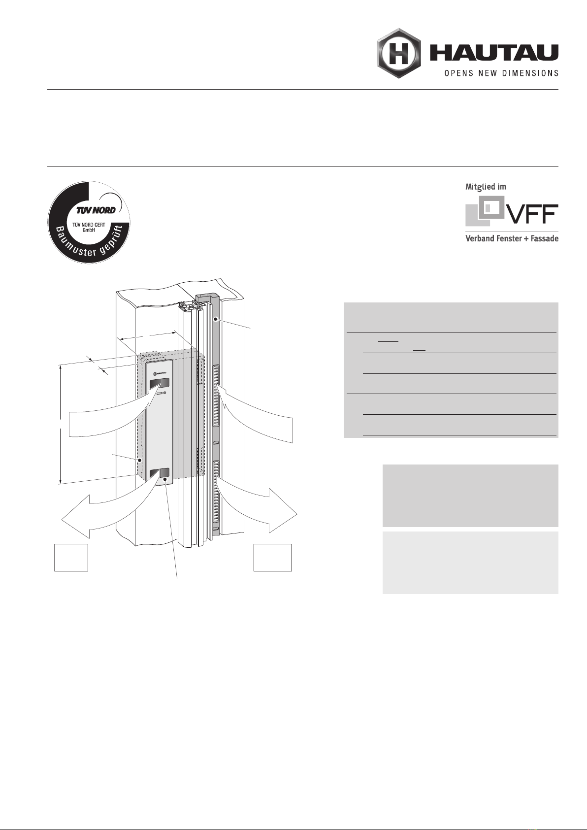
Blende mit integrierter Bedieneinheit und Anzeige
Cover with integrated operating panel and display
Gehäuse
housing
Luftführungsprofil
air duct profile
Beispiel: Ausführung links;
Ausführung rechts entsprechend
Example: version left;
version right accordingly
08/2019243364H
Inhaltsverzeichnis
Bestimmungsgemäße Verwendung / Warnung vor Fehlgebrauch .. 2
Technische Daten ........................................................................ 2
Sicherheitshinweise ...................................................................... 3
Montagehinweise ......................................................................... 3
Prüfung ........................................................................................ 3
Gewährleistung ............................................................................ 3
Entsorgung ................................................................................. 3
Teile-Übersicht ............................................................................. 4
Vorbereitung der Wand ................................................................ 5
Elektroinstallation ......................................................................... 6
Montage der Luftführung .............................................................. 7
Montage des Lüftergehäuses ....................................................... 7
Abdichtung des Lüfters ................................................................ 8
Anschluss der Blende .................................................................. 9
Einbaubeispiele .......................................................................... 10
EG Einbauerklärung ................................................................... 16
Contents
Intended use / Warning of forseeable misuse ........................... 2
Technical data .......................................................................... 2
Safety information .................................................................... 3
Mounting information ............................................................... 3
Test .......................................................................................... 3
Warranty .................................................................................. 3
Disposal .................................................................................. 3
Parts overview .......................................................................... 4
Preparation of the wall .............................................................. 5
Electrical installation ................................................................. 6
Mounting of air duct profile ....................................................... 7
Mounting of housing of window fan ......................................... 7
Sealing of window fan .............................................................. 8
Connection of cover ................................................................. 9
Mounting examples ................................................................ 10
EG declaration of incorporation .............................................. 16
VENTRA®301 E/N
Montageanleitung
Mounting instructions
D
HINWEIS:
Für den Einbau des Lüfters VENTRA® 301 E/N
bei Renovierung ist auch die „Zusatzanleitung für
Einbau bei Renovierung“, Artikelcode: 244645,
zu verwenden.
Maße in mm.
NOTE:
For installation of window fan VENTRA® 301 E/N
in case of retrofitting, the document „Additional
instructions in case of retrofitting“, item code:
244645, has to be used, too.
Dimensions in mm.
Anwendungsbereich / Application
min. RAH / min. frame overall height:
für nicht bodentiefe Fenster 750 mm
for windows not floor to ceiling
für bodentiefe Fenster 1620 mm
for floor to ceiling windows
min. Wandstärke / min. wall thickness:
für Fenster ohne Rollladen 240 mm
for windows without rolling shutter
für Fenster mit Rollladen 290 mm
for windows with rolling shutter

2
Bestimmungsgemäße
Verwendung
Das dezentrale Lüftungsgerät VENTRA® 301 E/N ist für die
Be- und Entlüftung einzelner Wohnräume sowie Küchen,
Bäder, Keller- und Toiletten- oder ähnlich genutzten Räumen
bestimmt. Die Wahl des Einbauortes für den VENTRA hat
unter Berücksich tigung der Schutzart IP 20 zu erfolgen.
Zum vollständigen Einbau gehört noch ein Luftführungsprofil,
um sowohl die Luftströmungen als auch das Kondenswasser
zu leiten.
Das Lüftungsgerät wird seitlich an einen Fensterrahmen
angebracht und muss beim Einbau des Fensters nach
den Richtlinien des Fensterbauers fachgerecht an die Wand-
konstruktion angebaut werden.
Ein Einbau des Lüfters in einem Raum mit raumluftabhängiger
Feuerstätte ist nicht zulässig. Wird der Lüfter in einem Raum
mit Feuerstätte betrieben, so sind die örtlichen Feuerungs-
verordnungen einzuhalten.
Mit dem Datenkabel und über die HAUTAU-Schnittstelle kann
eine Anbindung an die HAUTAU-Smart-Building-Funktionen
erfolgen.
Wird eine Anbindung über das Datenkabel nicht gewünscht,
sind die Kabelenden abzuisolieren und das Kabel ist zugänglich
zu verlegen.
Intended use
The decentralized VENTRA® 301 E/N window fan is intended to
be used for the ventilation of single living rooms and kitchens,
bath rooms, basements and toilets or similarly used rooms.
The choice of the installation location for the VENTRA must
be made taking into account protection system IP 20.
To complete the installation, an air duct profile is to be used to
guide the airflows and the condensed water as well.
The window fan is installed laterally to a window frame. During
installation, it has to be mounted to the wall construction in a
professional manner acc. to the guidelines of the window
manufacturer.
The use of the window fan in a room with open flue fireplace is
not permitted. If the window fan will be operated in a room with
a fireplace, the local firing regulations habe to be observed.
With the data cable and via the HAUTAU interface a connection
to the HAUTAU Smart Building functions can be achieved.
If a connection via the data cable is not desired, the cable ends
have to be stripped and the cable has to be routed accessibly.
Nennspannung 230 V AC
Einschaltdauer 100 %
Luftmengen Stufe 1: 8 m³/h
Stufe 2: 15 m³/h
Stufe 3/4*: 30 m³/h
Leistung Stufe 1: 3,8 W
Stufe 2: 8,2 W
Stufe 3/4*: 34,5 W
Wärmebereitstellungsgrad Stufe 1: max. 86,4 %
Stufe 2: max. 85,5 %
Stufe 3/4*: max. 76,6 %
Eigengeräusch Stufe 1 Stufe 2 Stufe 3/4*
LN in dB(A) 25 37 63
Schalldämmwert Stufe 1 Stufe 2 Stufe 3/4*
Dn, e, w in dB 41 41 39
Filter Standard: G3
optional: M5
Schutzart IP 20
Anschlusstechnik Anschlussleitung 3x 0,75 mm², 2 m
Datenkabel 3x 0,25 mm², 3 m
Gehäuse:
Abmessungen (HxBxT) 485 x 240 x 98 mm
Material EPP
Blende:
Abmessungen (HxB) 505 x 110 mm
Material ASA, UV stabilisiert
Farben weiß, silber
Luftführungsprofil:
Material Aluminium
Farben weiß, silber, schwarz
Luftführungsprofil für Fenster ohne Rollladen:
Abmessungen 50 x 37 mm
Länge 1500 mm, 3000 mm
Luftführungsprofil für Fenster mit Rollladen:
Abmessungen 30 x 80 x 50 mm
Länge 1500 mm, 3000 mm
*) in Stufe 4 schaltet der Lüfter nach einer Stunde
automatisch in Stufe 1 zurück
Technische Daten Technical data
Rated voltage 230 V AC
Duty cycle 100 %
Quantity of air Level 1: 8 m³/h
Level 2: 15 m³/h
Level 3/4*: 30 m³/h
Power Level 1: 3,8 W
Level 2: 8,2 W
Level 3/4*: 34,5 W
Heat recovery rate Level 1: max. 86,4 %
Level 2: max. 85,5 %
Level 3/4*: max. 76,6 %
Self-noise level level 1 level 2 level 3/4*
LN in dB(A) 25 37 63
Sound insulation value level 1 level 2 level 3/4*
Dn, e, w in dB 41 41 39
Filter Standard: G3
optional: M5
Protection system IP 20
Connection technology connecting cable 3x 0,75 mm², 2 m
Data cable 3x 0,25 mm², 3 m
Housing:
Dimensions (HxWxD) 485 x 240 x 98 mm
Material EPP
Cover:
Dimensions (HxW) 505 x 110 mm
Material ASA, UV stabilised
Colours white, silver
Air duct profile:
Material Aluminium
Colours white, silver, black
Air duct profile for windows without rolling shutter:
Dimensions 50 x 37 mm
Length 1500 mm, 3000 mm
Air duct profile for windows with rolling shutter:
Dimensions 30 x 80 x 50 mm
Length 1500 mm, 3000 mm
*) in level 4 the window fan switches automatically
after one hour back into level 1
Warnung vor vorher-
sehbarem Fehlgebrauch
Das dezentrale Lüftungsgerät VENTRA® 301 E/N
darf nicht als Bautrockner verwendet werden!
Um Schäden am Gerät zu vermeiden, ist dieses während
der Trocknungsphase des Bauobjekts allpolig von der
Versorgungsspannung zu trennen.
Warning of forseeable misuse
The decentralized VENTRA® 301 E/N window fan
must not be used as a building dryer!
To avoid damage to the equipment, disconnect it from the
power supply at all poles during the drying phase of the
construction object.

3
Für die Sicherheit von Personen ist es wichtig,
die folgenden Anweisungen zu befolgen:
Herstellererklärung/Stand der Technik
Der Lüfter wurde gemäß der anzuwendenden europäischen
Richtlinien hergestellt und geprüft. Er entspricht dem Stand
der Technik und erfordert qualifiziertes Fachpersonal bei der
Montage, Wartung etc.
Personal
Die fachgerechte Ausführung des elektrischen Anschlusses darf
nur durch eine Elektrofachkraft (z. B. nach DIN VDE 1000-10)
erfolgen! Der Einbau des Lüfters muss durch Personal erfolgen,
welches entsprechend dem Stand und nach anerkannten
Regeln der Technik unterwiesen wurde.
Aufbewahrung von Dokumenten/Einweisung
Bewahren Sie diese Montageanleitung für den späteren
Gebrauch und die Wartung auf. Händigen Sie die Bedienungs-
anleitung dem Endanwender aus und nehmen Sie eine
Einweisung vor.
Installation und Bedienung
WARNUNG 230 V AC:
Gefahr für Personen durch elektrischen Strom!
Gefährliche Spannung. Kann Tod, schwere Körperver-
letzung oder erheblichen Sachschaden verursachen.
Trennen Sie das Gerät allpolig von der Versorgungs-
spannung bevor Sie es öffnen, montieren oder den
Aufbau verändern. Z. B. VDE 0100 für 230 V Netz-
anschluss beachten.
ACHTUNG: Falls Sie die Arbeitsschritte nicht
beachten, führt dies zur Zerstörung des Lüfters.
Falsche Handhabung gefährdet das Material. Lassen
Sie keine Flüssigkeit ins Geräteinnere gelangen!
In dieser Anleitung sind ausschließlich Arbeiten darge-
stellt, die für die Montage des VENTRA® relevant sind.
Die in dieser Anleitung beschriebenen Verfahren stellen
nur eine Auswahl von Möglichkeiten der Montage dar.
In jedem Fall sind die baulichen Gegebenheiten so zu
berücksichtigen, dass für das Gebäude geltende
Normen nicht verletzt werden.
Führen Sie die Montage entsprechend dem Stand und
nach anerkannten Regeln der Technik aus.
Beachten Sie bei der Verwendung von Dicht-/Kompri-
bändern oder anderen Dichtmaterialien die jeweiligen
Verarbeitungs richtilinien des Herstellers.
Überprüfen Sie nach der Installation und nach jeder
Veränderung der Anlage alle Funktionen durch Probelauf.
Für den Lüfter gelten die Allgemeinen Geschäftsbedingungen
(AGB) der Fa. HAUTAU (Internet: www.HAUTAU.de).
Für Länder der Europäischen Union:
Führen Sie dieses Gerät nach der Verwendung einer
getrennten Müllsammlung zu. Entsorgen Sie den Lüfter
nicht über den unsortierten Hausmüll.
Prüfung
Gewährleistung
Entsorgung
In these instructions only works are shown, that are
relevant for the mounting of the VENTRA®.
The procedures described within these instructions,
are a selection of mounting alternatives, only.
In any case, the structural conditions have to be
considered in such a way, that the applicable building
standards will not be violated.
Complete the installation according to the state of the art
and according to recognised rules of technology.
If using gasket/compression strips or other sealing
materials, consider the corresponding processing
guide-lines of the manufacturer.
Check all functions by a test run after installation and after each
modification of the equipment.
The general terms and conditions (GTC) from HAUTAU are
applied to the window fan (website: www.HAUTAU.de).
For countries within the European Union:
After usage, apply selective collection to the device.
Do not dispose of the window fan as unsorted
domestic waste.
Test
Warranty
Disposal
Safety information
The safety of personnel requires that the following
instructions will be observed:
Manufacturer’s declaration/state of the art
The window fan has been manufactured and tested in conformity
with all applicable European directives. The window fan complies
with the state of the art and requires qualified personnel for
installation, maintenance, etc.
Personnel
Professional execution of electrical connection has to be entrusted
to trained electricians! (as specified e. g. in DIN VDE 1000-10)
The mounting of the window fan has to be performed by
personnel, which has been instructed according to the state of
the art and according to recognised rules of technology.
Storing documents/instructions
Store these instructions for future reference and maintenance.
Make these installation instructions available to the end user and
provide instructions.
Installation and operation
WARNING 230 V AC:
Danger to persons due to electricity!
Dangerous voltage. Can cause death, serious injury or
considerable material damage. Disconnect the equip-
ment from the power supply at all poles before opening,
assembling or carrying out any structural alterations.
Observe e. g. VDE 0100 for 230 V power connection.
CAUTION: Failure to follow the work steps will destroy
the device.
Improper handling endangers the material. Do not allow
any liquid to enter the interior of the device!
Montagehinweise Mounting information
Sicherheitshinweise
4
8
Beispiel: Ausführung links;
Ausführung rechts entsprechend
Example: version left;
version right accordingly
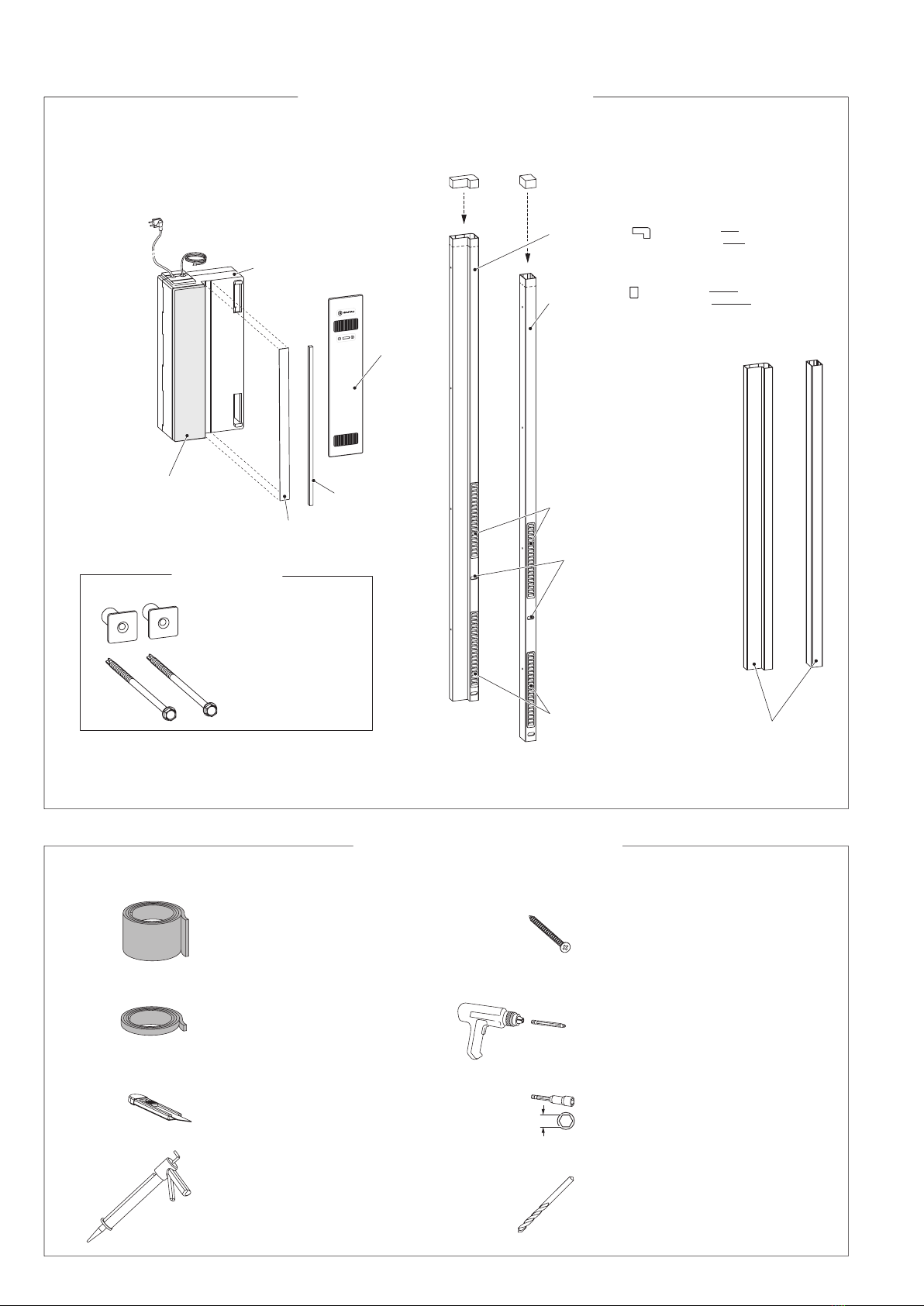
Lieferumfang (abhängig von der Bestellung)
scope of delivery (depending on the order)
empfohlenes Zubehör / Werkzeug
recommended accessories / tools
Netzkabel
mains cable Datenkabel
data cable
Lüfter
window fan
Einputzhilfe (nach dem
Einputzen zu entfernen)
plaster aid (remove
after plastering) Abdeckleiste
cover fillet
Dichtstreifen
(Kompriband)
Sealing
(compression strip)
Befestigungsset *)
Fixing accessories *)
*) bei Neubau-Installation; für Einbau bei Renovierung
siehe Zusatzanleitung 244645
in case of new equipment installation; in case of retrofitting
refer to additional instructions 244645
Anschraubhülsen
Bolting bushings
Bohrschrauben
Drilling screws
Blende
cover
Luftführung für Fenster mit Rollladen
air duct profile for windows with rolling shutter
beigefügte Stopfen oben in die fertig abgelängten Profile stecken
put enclosed stoppers on top into the profile cut to length
Luftführung für Fenster ohne Rollladen
air duct profile for windows without rolling shutter
Außengitter
für Außenluft
outside grille
for outer air
Außengitter
für Fortluft
outside grille
for exhaust air
Entwässerungsschlitze
cut-out for drainage
Verlängerungsprofil
Luftführung (optional)
extension for air duct profile
(optional)
Multifunktions-Dichtband
multifunctional gasket strip
Kompriband
compression strip
Cutter
Cutter
Akku-Schrauber/Kreuzschrauben-Bit
cordless screwdriver/Phillips screw bit
Steckschlüssel-Einsatz, Gr. 8
wrench socket, size 8
Metallbohrer Ø 12
Metal drill Ø 12
spritzbarer Dichtstoff
extrudable sealant
Ø 4,8 x 130
Teile-Übersicht / Parts overview
10 Schrauben
10 screws
z. B.
e. g. Ø 4,8 x 20

5
1110 + a
250 + a
(~ 250)
~ 110
~ 8
(bei Renovierung)
~ 120
Durch den Einbau des VENTRA®verändert sich
die Position des gesamten Fensters und der
Fensterbank um das betreffende Maß. Dies ist
durch ein entsprechendes Anschlussprofil an
der oberen Seite auszugleichen (ohne Abb.).
By installing the VENTRA®, the position of the whole
window/window sill will be changed by the respective
measure. This has to be compensated by an
appropriate connection profile at the top side (no ill.).
mit VENTRA®,
ohne Rollladen
with VENTRA®,
without rolling shutter
ohne VENTRA®
without VENTRA®
Fensterbank
window sill
VENTRA®-Gehäuse mittels beiliegender
Einputzhilfe ca. 8 mm einputzen
(ggf. vorher das korrekte Maß bestimmen)
plaster the VENTRA®housing approx. 8 mm
by means of the enclosed plaster aid
(determine the correct measure in advance)
a
~ 500
505
~ 10
min. 525
*
*
RAH: min. 750
~ 205 ~ 45
30 37
~ 1110 1)
~ 250 2)
RAH: min. 1620
VENTRA®
VENTRA®
(in case of retrofitting)
Ansicht Z
view Z
Ansicht Y
view Y
Ansicht von innen bei Ausführung links;
Ausführung rechts entsprechend
view from inside for version left;
version right accordingly
Luftführungsprofil
air duct profile
Beispiel: für Fenster mit VENTRA®und Rollladen;
Referenz für Fenster ohne Rollladen entsprechend
example: for windows with VENTRA® and rolling shutter;
reference for windows without rolling shutter accordingly
glatt verputzen
smooth plastering
Wandvorbereitung / Preparation of the wall
Prüfung der Einbaumaße/-position
Checking of the installation dimensions/position
Wandausbruch verputzen
Plastering the wall block-out
außen / outside
innen / inside
Ansicht Z / view Z
Ansicht Y (vergrößert) / view Y (enlarged)
VENTRA®
VENTRA®
Luftführungsprofil
air duct profile
Blende
cover
bodentiefe Fenster (Profillänge 3000):
floor to ceiling windows (profile length 3000):
nicht bodentiefe Fenster (Profillänge 1500):
windows not floor to ceiling (profile length 1500):
1)
bodentiefe Fenster (Profillänge 3000):
floor to ceiling windows (profile length 3000):
2)
nicht bodentiefe Fenster (Profillänge 1500):
windows not floor to ceiling (profile length 1500):
*) Scharnierband
Hinge

6
230 V AC
3
5
4
2
6
7
230 V AC
=
N =
L =
1
68,5
61
31
Endgültiger elektrischer Anschluss (5-7)
Gerät vom Netz nehmen und Netzstecker entfernen.
Die 3-adrige Anschlussleitung an das Netz anschließen.
Die Blende ist endgültig erst nach dem Einputzen des
Lüftergehäuses anzuschließen.
Ultimate electrical connection (5-7)
Take the unit from the mains supply and remove the mains
plug. Connect the 3-wire cable to the mains supply.
The cover is to be connected ultimately only after plastering of
the housing of the window fan.
grün/gelb
green/yellow
Vorbereitung elektr. Anschluss
Preparation electrical connection
Leerrohr Ø 16 mm
empty conduit Ø 16 mm
Verteilerdose
Junction box
Leerrohr Ø16 mm für Datenkabel
empty conduit Ø16 mm for data cable
Sicherungskasten mit
allpoliger Trennvorrichtung
Fuse box with all-pole
disconnecting switch
HINWEIS:
Strom- und Datenkabel sind in
getrennte Leerrohre zu verlegen.
Power cable and data cable have
to be placed in separated empty
conduits.
nach dem Berühren der Taste ”+” ...
after touching the button „+“ ...
rote LED blinkt
bei Störung
red LED blinks in
case of error
... müssen LED’s leuchten
... LED’s have to lit
blau
blue
braun
brown
Elektroinstallation
WARNUNG 230 V AC: Verletzungs- oder Lebens-
gefahr durch einen Stromschlag!
ACHTUNG: Lassen Sie den elektrischen Anschluss
von einer Elektrofachkraft durchführen!
Electrical installation
WARNING 230 V AC: Risk of injury or electrocution!
ATTENTION: Electrical connection has
to be performed by a qualified electrician!
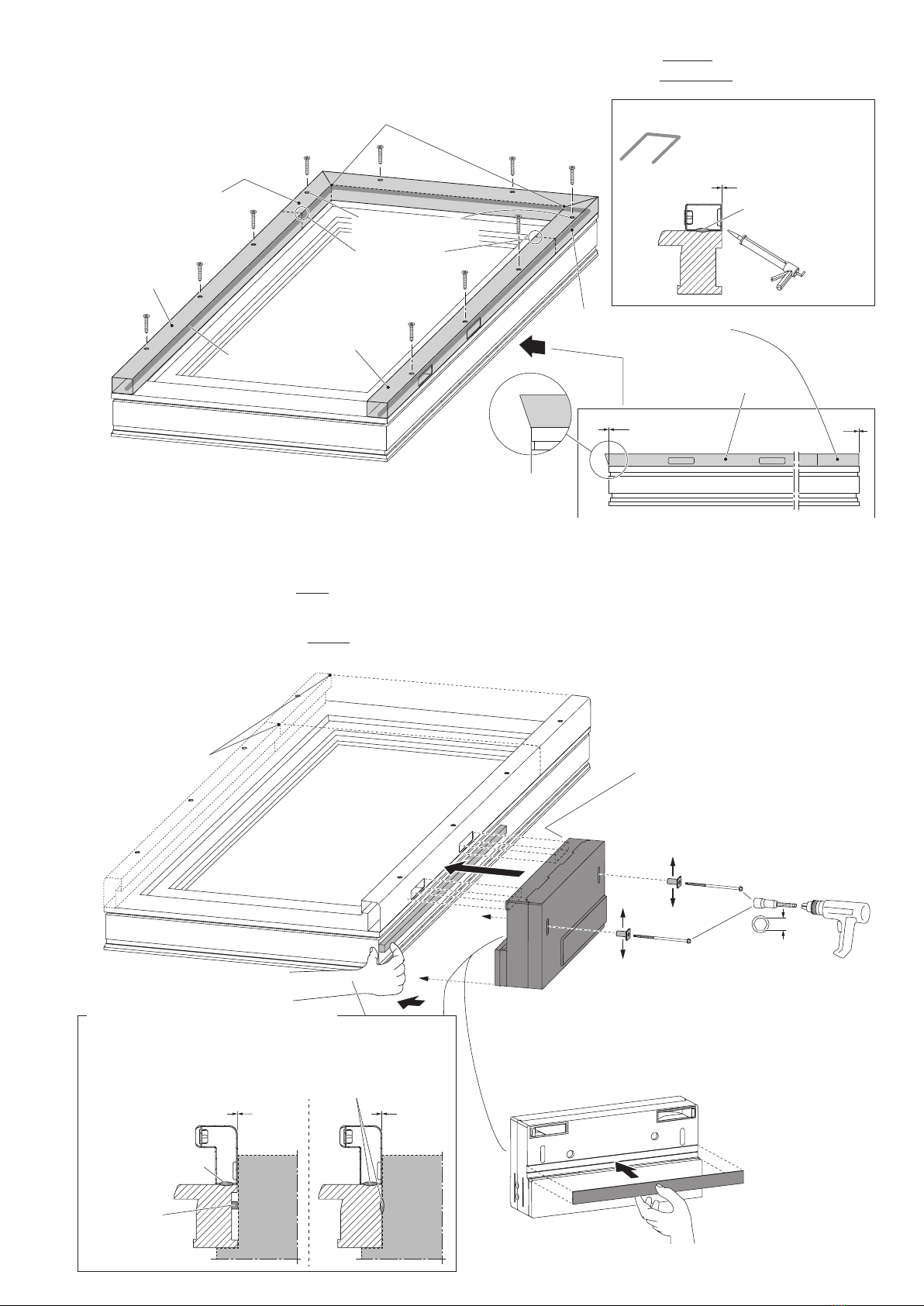
Funktionstest (1– 4)
Vor dem Einbau des Lüfters in die Fensterlaibung muss das
Gerät auf einwandfreie Funktion geprüft werden. Hierfür ist die
Einputzhilfe zu entfernen und die Blende zu montieren. Nach
dem Funktionstest ist die Blende abzunehmen und die Einputz-
hilfe wieder am Lüftergehäuse anzubringen.
Functional check (1- 4)
Before mounting the window fan into the reveal, the device
has to be checked for proper operation. For that the plaster
aid has to be removed and the cover has to be installed. After
functional check the cover has to be taken off and the plaster
aid has to be attached to the housing of the window fan again.
7
00
Ø 4,8 x ...
0
(siehe Schnitt)
2
1
1
3
5
0
Ø 4,8 x ...
1
2
5 *
3
4 *
1
2
2x
Ø 4,8 x 130
8
VENTRA VENTRA
00
Beispiel: Ausführung links;
Ausführung rechts entsprechend
Example: version left;
version right accordingly
Luftführung
air duct profile
ggf. bohren (Ø 12)
drill, if applicable (Ø 12)
ggf. Verlängerungsprofil
extension profile, if applicable
ggf. Verlängerungsprofil
extension profile, if applicable
Luftführung / Gegenstück
air duct profile / counterpart
Gegenstück zur
Luftführung
counterpart of
air duct profile
Ausrichtung des VENTRA®-Gehäuses zu
den Aussparungen der Luftführung:
Positionierhilfen verwenden
alignment of the VENTRA®-housing to the
cut-outs of the air duct profile:
use positioning assistance at the housing
Bohrschrauben durch die Anschraubhülsen stecken;
Ausrichtung der Hülsen entsprechend des Profils
put the drilling screws through the bolting bushings;
alignment of bushings according to profile
*) bei nachträglichem Einbau (Renovierung): s. Anleitung 244645
*) in case of retrofitting, please refer to mounting instructions 244645
Abdeckleiste** aufstecken
mount cover fillet*
Luftführungsprofile
zueinander ausrichten
align air duct profiles
to each other
seitliche Luftführungsprofile zueinander ausrichten
align lateral air duct profiles to each other
**) in Verpackungseinheit
“Blende“ enthalten
**) included in packaging unit „Cover“
Abdichtung Fensterrahmen / VENTRA®
Sealing window frame / VENTRA®
Kompriband
compression strip
spritzbarer Dichtstoff
extrudable sealant
spritzbarer Dichtstoff
extrudable sealant
Variante 1
version 1
Variante 2
version 2
außen
outside
unten
bottom
innen
inside
oben
top
außen
outside
unten
bottom
innen
inside
oben
top
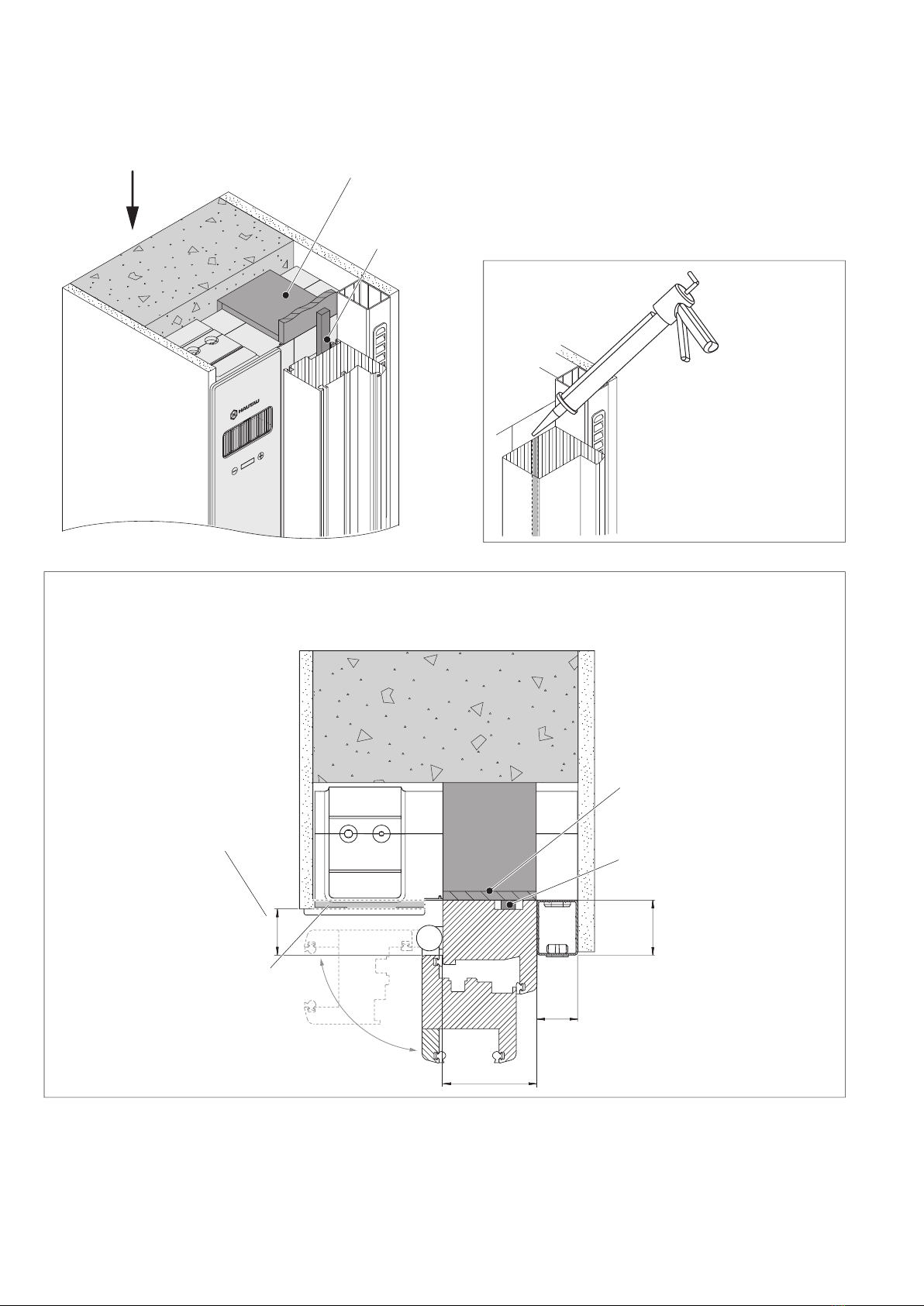
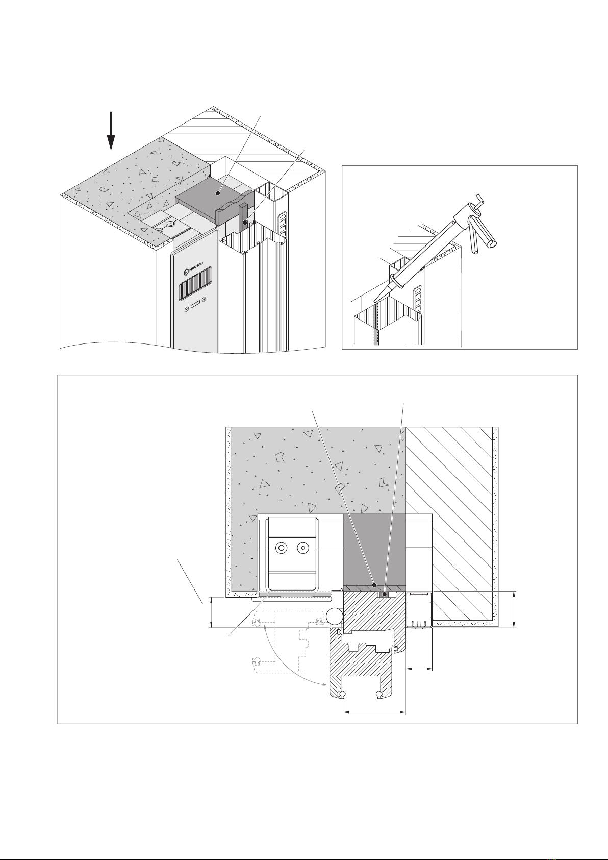
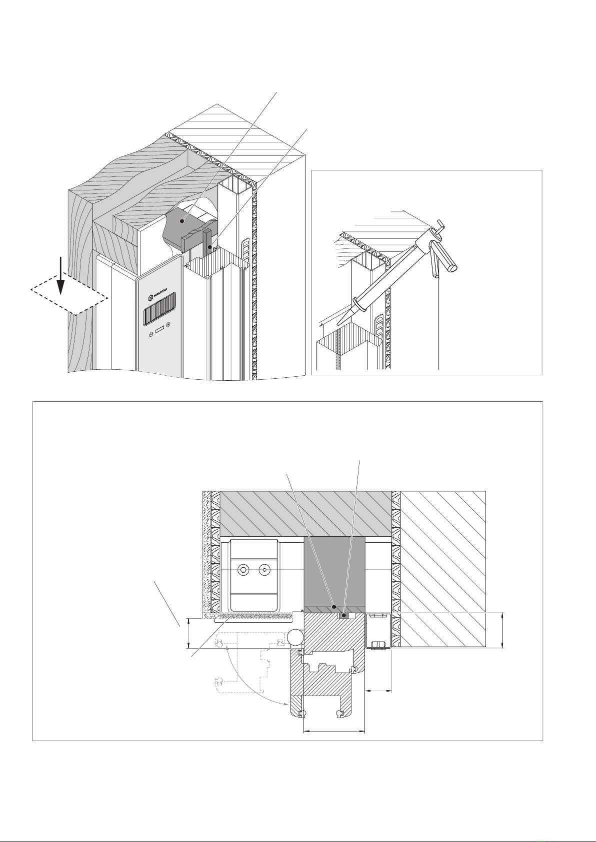
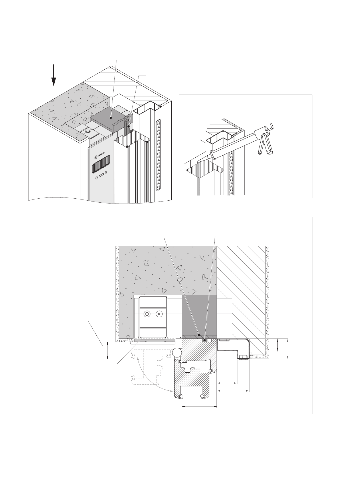
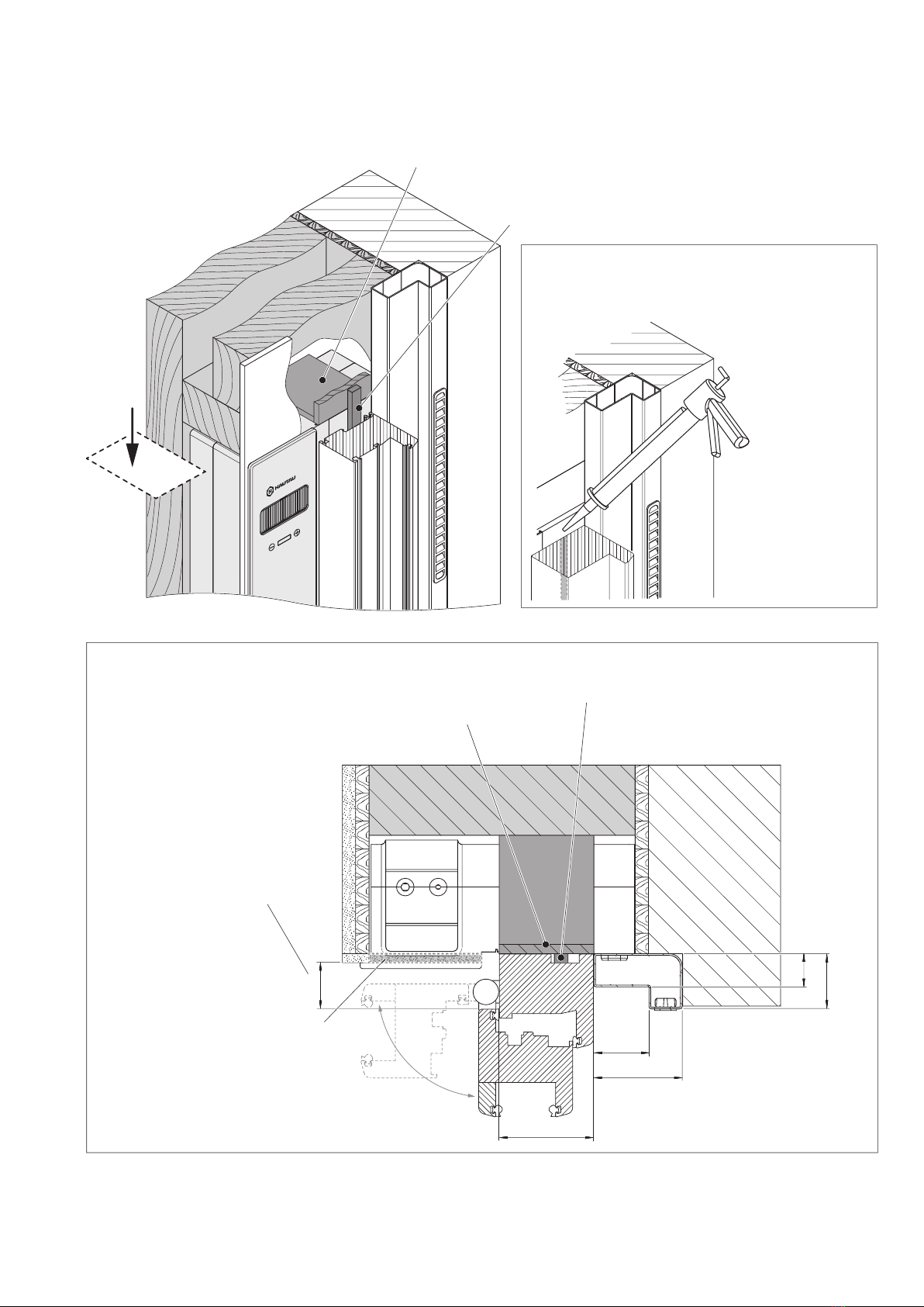
Montage der Luftführung (Beispiel: für Fenster ohne Rollladen)
Mounting of air duct profile (example: for windows without rolling shutter)
Montage des Lüftergehäuses
(Beispiel: für Fenster mit Rollladen; für Fenster ohne Rollladen entsprechend)
Mounting of housing of window fan
(example: for windows with rolling shutter;
(for windows without rolling shutter accordingly)
Referenz für Positionierung am
Fensterbank-Anschlussprofil
reference for positioning at
window sill connection profile
spritzbarer Dichtstoff
extrudable sealant
wind-/wasserdichter Abschluss
zum Fensterrahmen
wind-/water-tight sealing to the
window frame
beim Gehren auf Radien achten
pay attention to radii
when mitering
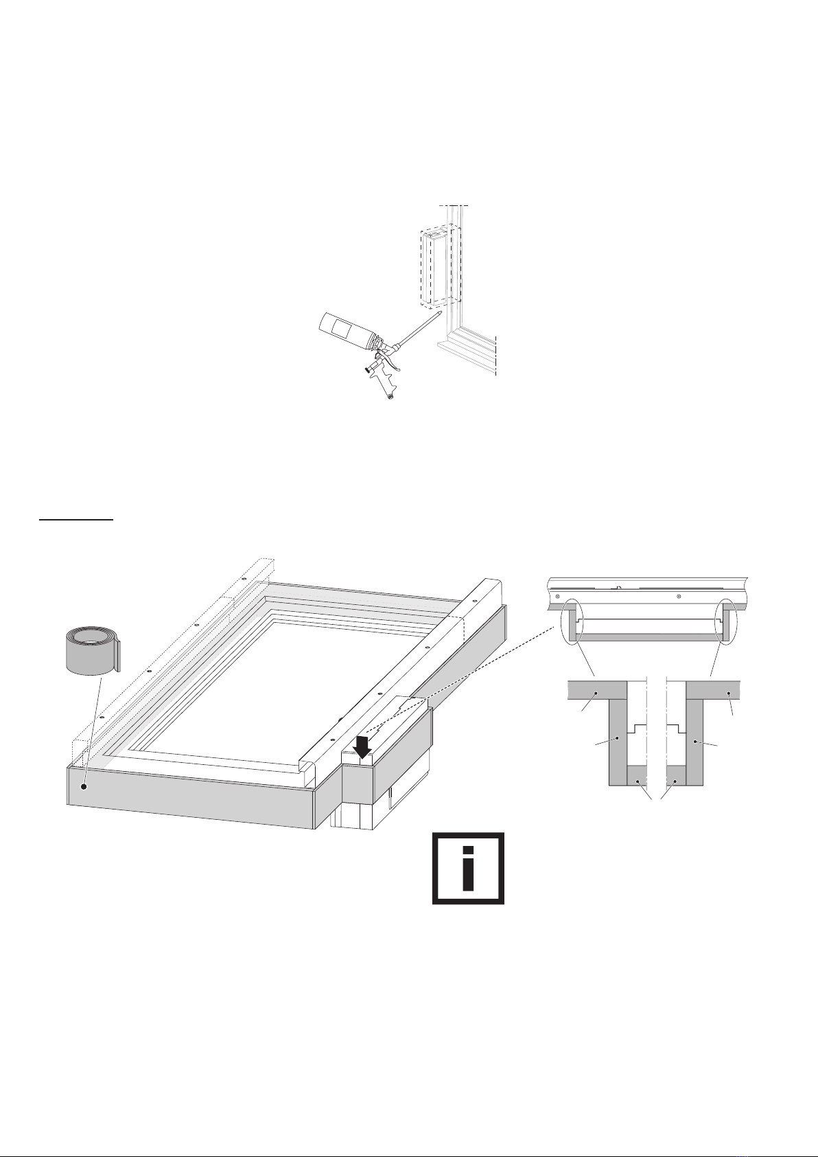
8
M
o
n
t
a
g
e
-
S
c
h
a
u
m
1.
2.
3.
4.
5.
2
1
3
Multifunktions-Dichtband
multifunctional gasket strip
Wichtiger Hinweis:
Nach dem Aufbringen des Multifunktions-
Dichtbandes muss der Einbau des Rahmens
inkl. VENTRA®unverzüglich erfolgen.
Important note:
After attaching the multifunctional gasket strip
the mounting of the frame including VENTRA®
has to be carried out immediately.
Stückelung des
Multifunktions-
Dichtbandes
Segmentation of
the multifunctional
gasket strip
Verwendung des Multifunktions-Dichtbandes entsprechend
den Verarbeitungsrichtlinien des Herstellers
usage of multifunctional gasket strip according to corresponding
processing guidelines of the manufacturer
außen
outside
unten
bottom
innen
inside
die Hohlräume sind mit
Montageschaum auszufüllen
the cavities have to be filled
with mounting foam
Die in diesem Abschnitt beschriebenen Verfahren stellen
nur eine von vielen Möglichkeiten der Montage dar.
In jedem Fall sind die baulichen Gegebenheiten so zu
berücksichtigen, dass für das Gebäude geltende Normen
nicht verletzt werden.
Für den Renovierungsfall wird die
Verwendung der Adapterplatte gemäß
Anleitung 244645 empfohlen.
For retrofitting, the use of the adapter
plate according mounting instructions
244645 is recommended.
The procedures described within this section, are a
selection of the multitude of mounting alternatives, only.
In any case, the structural conditions have to be
considered in such a way, that the applicable building
standards will not be violated.
Abdichtung des Lüfters
Nachträglicher Einbau: mit Montageschaum
Retrofitting: with mounting foam
Sealing of window fan
oben
top
Neubau: mit Multifunktions-Dichtband
New equipment: with multifunctional gasket strip

9
2
3
1
Anschluss der Blende
Connection of cover
Blende
cover
Einputzhilfe entfernen
remove plaster aid
Blende anschließen und
am Gehäuse montieren
connect cover and
attach it to the housing
10
Ansicht Z
view Z
37
max. 102
50
≥ 40
Multifunktions-Dichtband
multifunctional gasket strip
Multifunktions-Dichtband
multifunctional gasket strip
VENTRA®-Gehäuse mittels beiliegender
Einputzhilfe ca. 8 mm einputzen
(ggf. vorher das korrekte Maß bestimmen)
plaster the VENTRA®housing approx. 8 mm
by means of the enclosed plaster aid
(determine the correct measure in advance)
Die Blende trägt um min. 5 mm auf;
bei Montage des VENTRA®auf der
Bandseite muss ausreichend Platz
zwischen dem Flügel in geöffneter
Stellung und der Blende sein.
The cover reduces the free space by at
least 5 mm; when installing the VENTRA®
on the hinge side, there must be sufficient
space between the sash in open position
and the cover.
Kompriband zwischen PVC-/Alu-Rahmenprofil
und VENTRA®-Gehäuse
compression strip between PVC/Alu frame profile
and housing of VENTRA®
bei Holz-Rahmenprofil:
in case of timber frame profile:
spritzbarer Dichtstoff
zwischen Holz-Rahmen-
profil und VENTRA®-
Gehäuse
extrudable sealant
between timber frame
profile and housing of
VENTRA®
Ansicht Z
view Z
Kompriband
compression strip
bei Holz-Rahmenprofil:
spritzbarer Dichtstoff
(siehe oben)
in case of timber frame profile:
extrudable sealant (see above)
Einbaubeispiele / Mounting examples
Monolithische Bauweise ohne Rollladen
Monolithic construction without rolling shutter
11
Ansicht Z
view Z
37
50
≥ 40
max. 102
Die Blende trägt um min. 5 mm auf;
bei Montage des VENTRA®auf der
Bandseite muss ausreichend Platz
zwischen dem Flügel in geöffneter
Stellung und der Blende sein.
The cover reduces the free space by at
least 5 mm; when installing the VENTRA®
on the hinge side, there must be sufficient
space between the sash in open position
and the cover.
VENTRA®-Gehäuse mittels beiliegender
Einputzhilfe ca. 8 mm einputzen
(ggf. vorher das korrekte Maß bestimmen)
plaster the VENTRA®housing approx. 8 mm
by means of the enclosed plaster aid
(determine the correct measure in advance)
Multifunktions-Dichtband
multifunctional gasket strip
Multifunktions-Dichtband
multifunctional gasket strip
Kompriband zwischen PVC-/Alu-Rahmenprofil
und VENTRA®-Gehäuse
compression strip between PVC/Alu frame profile
and housing of VENTRA®
bei Holz-Rahmenprofil:
in case of timber frame profile:
spritzbarer Dichtstoff
zwischen Holz-Rahmen-
profil und VENTRA®-
Gehäuse
extrudable sealant between
timber frame profile and
housing of VENTRA®
Ansicht Z
view Z
Kompriband
compression strip
bei Holz-Rahmenprofil:
spritzbarer Dichtstoff
(siehe oben)
in case of timber frame profile:
extrudable sealant (see above)
Einbaubeispiele (Forts.) / Mounting examples (cont’d)
WDVS-Bauweise ohne Rollladen
ETICS construction without rolling shutter
12
Ansicht Z
view Z
37
50
≥ 40
max. 102
mit Innenaufbau
inside with covering Multifunktions-Dichtband
multifunctional gasket strip
Kompriband zwischen PVC-/Alu-Rahmenprofil
und VENTRA®-Gehäuse
compression strip between PVC/Alu frame profile
and housing of VENTRA®
bei Holz-Rahmenprofil:
in case of timber frame profile:
spritzbarer Dichtstoff
zwischen Holz-Rahmen-
profil und VENTRA®-
Gehäuse
extrudable sealant
between timber frame
profile and housing of
VENTRA®
Ansicht Z
view Z
Kompriband
compression strip
Multifunktions-Dichtband
multifunctional gasket strip
bei Holz-Rahmenprofil:
spritzbarer Dichtstoff
(siehe oben)
in case of timber frame profile:
extrudable sealant (see above)
VENTRA®-Gehäuse mittels beiliegender
Einputzhilfe ca. 8 mm einputzen
(ggf. vorher das korrekte Maß bestimmen)
plaster the VENTRA®housing approx. 8 mm
by means of the enclosed plaster aid
(determine the correct measure in advance)
Die Blende trägt um min. 5 mm auf;
bei Montage des VENTRA®auf der
Bandseite muss ausreichend Platz
zwischen dem Flügel in geöffneter
Stellung und der Blende sein.
The cover reduces the free space by at
least 5 mm; when installing the VENTRA®
on the hinge side, there must be sufficient
space between the sash in open position
and the cover.
Einbaubeispiele (Forts.) / Mounting examples (cont’d)
Bauweise mit Holzständerwerk ohne Rollladen
Construction with timber framework without rolling shutter

13
Ansicht Z
view Z
50
80
50
30
≥ 40
max. 102
Multifunktions-Dichtband
multifunctional gasket strip
Multifunktions-Dichtband
multifunctional gasket strip
Kompriband zwischen PVC-/Alu-Rahmenprofil
und VENTRA®-Gehäuse
compression strip between PVC/Alu frame profile
and housing of VENTRA®
bei Holz-Rahmenprofil:
in case of timber frame profile:
Ansicht Z
view Z
Kompriband
compression strip
spritzbarer Dichtstoff
zwischen Holz-Rahmen-
profil und VENTRA®-
Gehäuse
extrudable sealant between
timber frame profile and
housing of VENTRA®
bei Holz-Rahmenprofil:
spritzbarer Dichtstoff
(siehe oben)
in case of timber frame profile:
extrudable sealant (see above)
VENTRA®-Gehäuse mittels beiliegender
Einputzhilfe ca. 8 mm einputzen
(ggf. vorher das korrekte Maß bestimmen)
plaster the VENTRA®housing approx. 8 mm
by means of the enclosed plaster aid
(determine the correct measure in advance)
Die Blende trägt um min. 5 mm auf;
bei Montage des VENTRA®auf der
Bandseite muss ausreichend Platz
zwischen dem Flügel in geöffneter
Stellung und der Blende sein.
The cover reduces the free space by at
least 5 mm; when installing the VENTRA®
on the hinge side, there must be sufficient
space between the sash in open position
and the cover.
Einbaubeispiele (Forts.) / Mounting examples (cont’d)
Monolithische Bauweise mit Rollladen
Monolithic construction with rolling shutter
14
Ansicht Z
view Z
50
80
30
50
≥
40
max. 102
Multifunktions-Dichtband
multifunctional gasket strip
Multifunktions-Dichtband
multifunctional gasket strip
Kompriband zwischen PVC-/Alu-Rahmenprofil
und VENTRA®-Gehäuse
compression strip between PVC/Alu frame profile
and housing of VENTRA®
bei Holz-Rahmenprofil:
in case of timber frame profile:
Ansicht Z
view Z
Kompriband
compression strip
spritzbarer Dichtstoff
zwischen Holz-Rahmen-
profil und VENTRA®-
Gehäuse
extrudable sealant between
timber frame profile and
housing of VENTRA®
bei Holz-Rahmenprofil:
spritzbarer Dichtstoff
(siehe oben)
in case of timber frame profile:
extrudable sealant (see above)
VENTRA®-Gehäuse mittels beiliegender
Einputzhilfe ca. 8 mm einputzen
(ggf. vorher das korrekte Maß bestimmen)
plaster the VENTRA®housing approx. 8 mm
by means of the enclosed plaster aid
(determine the correct measure in advance)
Die Blende trägt um min. 5 mm auf;
bei Montage des VENTRA®auf der
Bandseite muss ausreichend Platz
zwischen dem Flügel in geöffneter
Stellung und der Blende sein.
The cover reduces the free space by at
least 5 mm; when installing the VENTRA®
on the hinge side, there must be sufficient
space between the sash in open position
and the cover.
Einbaubeispiele (Forts.) / Mounting examples (cont’d)
WDVS-Bauweise mit Rollladen
ETICS construction with rolling shutter
15
Ansicht Z
view Z
30
50
80
50
≥ 40
max. 102
mit Innenaufbau
inside with covering
Multifunktions-Dichtband
multifunctional gasket strip
Multifunktions-Dichtband
multifunctional gasket strip
Kompriband zwischen PVC-/Alu-Rahmenprofil
und VENTRA®-Gehäuse
compression strip between PVC/Alu frame profile
and housing of VENTRA®
bei Holz-Rahmenprofil:
in case of timber frame profile:
Ansicht Z
view Z
Kompriband
compression strip
spritzbarer Dichtstoff
zwischen Holz-Rahmen-
profil und VENTRA®-
Gehäuse
extrudable sealant between
timber frame profile and
housing of VENTRA®
bei Holz-Rahmenprofil:
spritzbarer Dichtstoff
(siehe oben)
in case of timber frame profile:
extrudable sealant (see above)
VENTRA®-Gehäuse mittels beiliegender
Einputzhilfe ca. 8 mm einputzen
(ggf. vorher das korrekte Maß bestimmen)
plaster the VENTRA®housing approx. 8 mm
by means of the enclosed plaster aid
(determine the correct measure in advance)
Die Blende trägt um min. 5 mm auf;
bei Montage des VENTRA®auf der
Bandseite muss ausreichend Platz
zwischen dem Flügel in geöffneter
Stellung und der Blende sein.
The cover reduces the free space by at
least 5 mm; when installing the VENTRA®
on the hinge side, there must be sufficient
space between the sash in open position
and the cover.
Einbaubeispiele (Forts.) / Mounting examples (cont’d)
Bauweise mit Holzständerwerk mit Rollladen
Construction with timber framework with rolling shutter

HAUTAU GmbH | Wilhelm-Hautau-Str. 2 | 31691 Helpsen | Germany | Tel +49 5724/393-0 | info@hautau.de | www.hautau.de
EG Einbauerklärung / EG declaration of incorporation
Other manuals for VENTRA 301 E/N
1
Table of contents
Other HAUTAU Fan manuals


