Powrmatic CECx 1400 User guide

Stamm International Corporation
PO Box 1929
Fort Lee, NJ 07024
Tel: 201-947-1700
Fax: 201-947-9662
E-mail: stamminc@pobox.com
Stamm International HQ
www.powrmatic.co.uk
www.powrmatic.co.uk
®
Powrmatic Limited
Hort Bridge, Ilminster
Somerset
TA19 9PS
tel: +44 (0) 1460 53535
fax: +44 (0) 1460 52341
e-mail: [email protected]
web: www.powrmatic.co.uk
Powrmatic Ireland
45 Broomhill Close
Tallaght
Dublin 24
tel: +353 (0) 1452 1533
fax: +353 (0) 1452 1764
e-mail: [email protected]
web: www.powrmatic.ie
Getting In Touch
Powrmatic pursues a policy of continues improvement in both design and performance of its products and therefore reserves the right to change, amend or
vary specifications without notice. Whilst the details contained herein are believed to be correct they do not form the basis of any contract and interested
parties should contact the Company to confirm whether any material alterations have been made since publication of this brochure.
EURO-AIR
QUALITY
ICOM
Energy Association
More information is available from our website by scanning the following QR code.
CECx
User, Installation & Servicing Manual
Issue 3.3 Jan 2020
Doc Ref: M503 Issue 3.3 Jan 2020

page no. 2 of 12 CECx Users, Installation & Servicing Instructions Doc Ref M503 issue 3.3 Jan 2020.
www.powrmatic.co.uk
Important: This certificate
must be kept with the appliance
Failure to provide a copy of the commissioning sheet invalidates the heater warranty
----------------------------------------------------
Powrmatic Ltd, Hort Bridge, Ilminster, Somerset, TA19 9PS
Tel: 01460 53535 Fax: 01460 52341
This is to certify that this destratification fan is guaranteed for a period of two years from the date of
original installation.
To make a claim
In the first instance you must contact your appliance supplier, or installer and provide:-
1. The appliance type and serial number.
2. The original commissioning documentation. As much detail as possible on the fault.
3. Your supplier, or installer, will then contact Powrmatic to make a guarantee claim on your behalf.
Conditions of Guarantee
1. The destatification fan must have been installed by a competent recognised installer, and in
accordance with the manufacturer’s instructions, I.E.E. regulations and local regulations.
2. The destatification fan has been used in accordance with the manufactures instructions.
3. No unauthorised repairs of modifications have been made. Powrmatic ‘General Conditions of
Sales’ have been observed.
4. Except for the obligation of Powrmatic Ltd to perform warranty repairs during the guarantee
period Powrmatic will not be liable in respect of any claim for direct or indirect consequential
losses, including loss of profits or increased cost arising from loss of use of the heater, or any
event arising there from.
CertificateOfGuarantee
Certificate of Guarantee
®

page no. 3 of 24
CECx Users, Installation & Servicing Instructions Doc Ref M503 issue 3.3 Jan 2020.
Title Section Contents Page
Pre Installation
1.1 Introduction 4
Dimensions 4
1.2 Technical data 5
1.3 General Requirements 5
Installation
2.1 Fitting the unit 6
2.2 Wiring Diagrams 8
2.3 Commissioning and Testing 9
2.4 Servicing 9
2.5 Replacement of Faulty Items 10
Additional Documents
3.1 Short List of Parts 10
Users,InstallationandServicingInstructions
CONTENTS
Contents

page no. 4 of 12 CECx Users, Installation & Servicing Instructions Doc Ref M503 issue 3.3 Jan 2020.
A) Maintenance
Regular servicing is essential to maintain efficient,
reliable and safe operation of the units. Users are strongly
recommended to have Calecons serviced by a qualified
person at least annually and preferably at the end of the
heating season.
Note: access must be maintained to the
Calecon units for servicing purposes.
WARNING: All Calecon units use electricity
to power them and contain moving parts,
the fan. It would be hazardous to tamper
with or attempt to service unless you are a
competent person in the field of Electrical work.
If you have any safety questions reference the servicing
and installation of this equipment please do not hesitate
to contact our head office for expert advice.
Your safety is paramount to us.
The Calecon unit you have installed is operated
automatically, by an inbuilt thermostat, to turn on when
the air temperature at high level exceeds the thermostat
setting.
The Calecon unit will automatically recirculate the
high level hot air in high roofed buildings drastically
reducing stratification and heat losses and minimise the
temperature gradient between low and high level.
The unit will turn off automatically when the air
temperature at high level falls below the setting on the
thermostat.
Mounted externally on the unit is the air temperature
sensing thermostat.
Units are fully pre-wired, fully tested and fitted with four
eyebolt suspension points.
In some installations a low level master control may be
installed to provide user control of the units.
Dim Model CECx 1400 CECx 2250 CECx 3350 CECx 4500 CECx 6500
A Enclosure Width 499 599 654 808 808
B Enclosure Depth 499 599 654 808 808
C Enclosure Height 260.5 260.5 260.5 187 187
D Overall Height 380 380 390 288 265
E Suspension ctrs 288 388 443 597 597
F Suspension ctrs 493.5 593.5 647.5 802.5 802.5
A
B
C
D
E
F
1.1Introduction
Dimensions

page no. 5 of 24
CECx Users, Installation & Servicing Instructions Doc Ref M503 issue 3.3 Jan 2020.
Model CECx 1400 CECx 2250 CECx 3350 CECx 4500 CECx 6500
Air flow
m3/s 0.77 1.2 1.58 2.1 3.07
m3/h 2772 4320 5688 7560 11052
Mounting Height (maximum) m 6 12 15 17 25
Mounting Height (suggested minimum) m 2.1 2.8 3.8 4.1 6.0
Electrics
Supply V/ph/Hz 230V/1Phase/50Hz
Start Current amps 1.3 2.9 3.1 5.6 5.7
Run Current amps 0.78 1.1 1.2 2.2 2.5
Dimensions
Width mm 499 599 654 808 808
Depth mm 499 599 654 808 808
Overall Height mm 380 380 390 288 265
Nett weight kg 16 22 25 29 33
Noise Level @ 5m (Q=2) LPA dB 50 50 50 52 52
1.3.2 Electrical Supply
WARNING: Wiring external to the unit must
be installed in accordance with the l.E.E.
Regulations and any local regulations which
apply.
Calecon units will require a 230V 50Hz 1ph fused supply
to operate and are equipped with a cable gland for mains
input via an isolator located adjacent to the unit.
The fan motor starting amps are approximately 3 times
the full load current.
1.3.1 Location
Calecon units will be effective in any high roofed building
where temperature stratification will otherwise occur.
Units should be installed at the highest available location
once the roof architecture and maximum mounting height
for the unit have been taken into account (see section 1.2).
Units should be placed in positions where the downward
directed airflow will not be impeded by racking or other
obstructions. Ensure units are not mounted so as to
obstruct the movement of overhead cranes, forklift trucks
etc.
Where multiple units are being used, their positioning
should ensure as even airflow pattern in the building
as practicable, taking into account the positions of any
affected occupants.
There should be a minimum of 1-metre free area between
the top of the units and the underside of the roof.
Calecon units sited adjacent to roof glazing or large
expanses of wall should be avoided as well as situated
close to open flued heaters.
'Free heat' can be gained by positioning the Calecon units
above heat generating lighting or machinery. Calecon
units positioned close to doorways help to quickly restore
comfortable conditions after door operation.
1.2 Technical Data
1.3GeneralRequirements

page no. 6 of 12 CECx Users, Installation & Servicing Instructions Doc Ref M503 issue 3.3 Jan 2020.
2.1.1.1.1Connecting
2.1.1.1.2Releasing
2.1.1GeneralFitting
The calecon unit is equipped with four suspension points,
one on each corner. These take the form of an eyebolt.
Using either our fixing kit, chain or wire rope, connect each
point to a rigid construction i.e. Unistrut, girders etc.
WARNING: Ensure the framework is
adequate to take the weight of the particular
destratification unit. Once the
destratification fan is in position, the wiring
can commence.
2.1.1.1 CECx Fixing Kit
The CECx fixing kit is a fast locking solution for quick and
easy suspension of our CECx destratification fans.
Features:
• Up to 6 times faster to install than traditional
methods
• Key-less - no tool required for adjustment
• Ergonomic buttons allow rapid adjustment
• Discreet and aesthetic design
• Load rated at 45 kg per wire with a 5:1 safety factor
• Supplied as a ready-to-use kit
Installation:
Roof Purlins
Fastener
Snap Hook
Wire Rope
2.1 Fitting the Unit

page no. 7 of 24
CECx Users, Installation & Servicing Instructions Doc Ref M503 issue 3.3 Jan 2020.
2.1.2. Electrical Connections
All units are fully pre-wired and only require final
connections for the incoming mains supply.
The electrical supply must be run to a point adjacent to
the unit and be suitably terminated to provide an isolation
point that will prevent activation of the unit during
servicing.
Refer to the specifications data in section 1.2 to ascertain
the electrical loading of the unit(s) being installed so that
cables of adequate cross-sectional area to safely carry
that load are used for the electrical installation.
The length of the conductors between the cord anchorage
and the terminals must be such that the current carrying
conductors become taut before the earth conductor if the
cable or cord slips out of the cord anchorage.
Any external controls that are used in conjunction with
the units must be of an approved type.
To wire the Calecon unit:-
1. Remove the two screws securing the electrical cover
plate to the casing and hinge down panel.
2. Pass the incoming supply cable through the cable gland
on the top of the unit.
3. Connect the live, neutral and earth wires to the
terminal block L, N and located behind the electrical
cover plate.
2.1 Fitting the Unit
4. Tighten the cable gland and secure the electrical cover
plate back to the casing.
230V 50Hz Supply
page no. 8 of 12 CECx Users, Installation & Servicing Instructions Doc Ref M503 issue 3.3 Jan 2020.
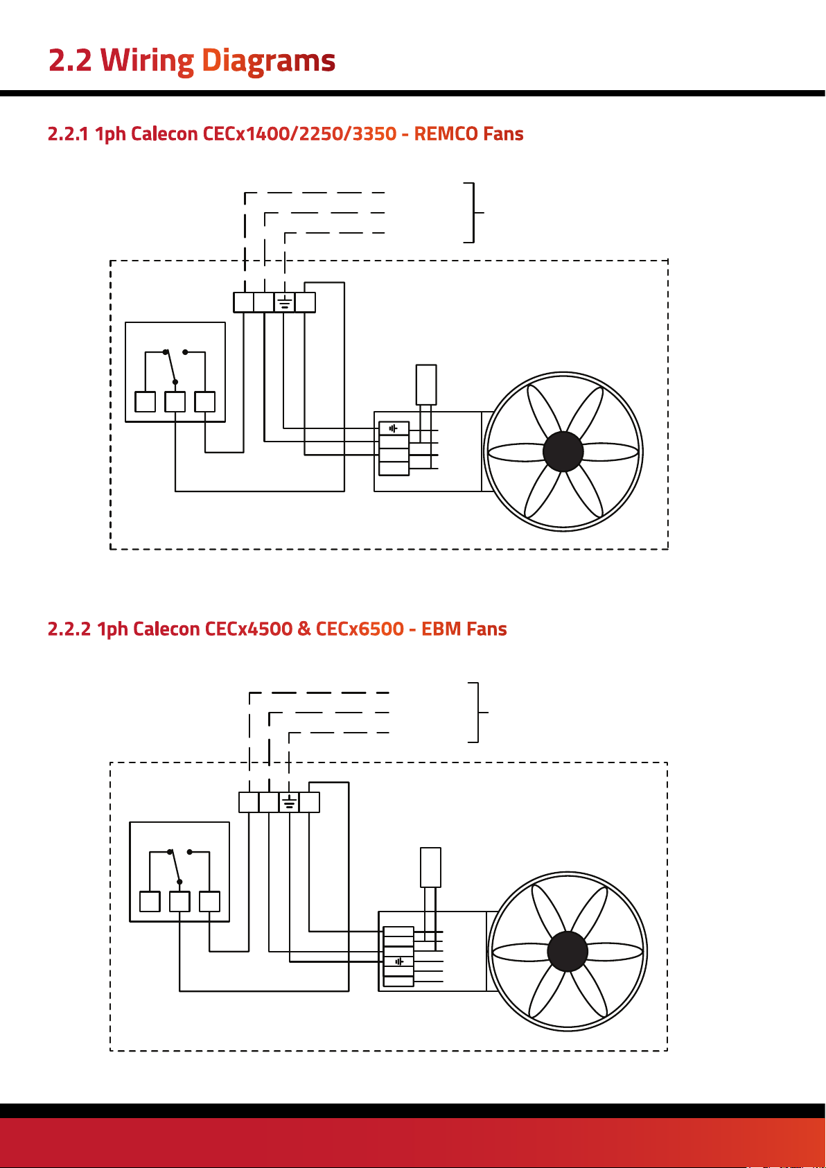
White
Brown
1
CEWAL RQ10
THERMOSTAT
23
1
NL
Gr/Yellow
Blue
Brown
MAINS SUPPLY
230V 1ph 50 Hz
EARTH
NEUTRAL
LIVE
CAPACITOR
White
Brown
1
CEWAL RQ10
THERMOSTAT
23
1
NL
Gr/Yellow
Blue
Brown
MAINS SUPPLY
230V 1ph 50 Hz
EARTH
NEUTRAL
LIVE
Blue
Brown
Black
Gr/Yel
2.2.1 1ph Calecon CECx1400/2250/3350 - REMCO Fans
Blue
Brow
Black
Gr/Yel
n
CAPACITOR
2.2 Wiring Diagrams
2.2.2 1ph Calecon CECx4500 & CECx6500 - EBM Fans

page no. 9 of 24
CECx Users, Installation & Servicing Instructions Doc Ref M503 issue 3.3 Jan 2020.
2.3.1. Electrical Installation
Checks to ensure electrical safety must be carried out by
a qualified person.
2.3.2. Final Adjustments and Testing
WARNING: When the electrical supply is
turned on the unit may start immediately
depending on the ambient temperature.
• Turn the thermostat on the side of the unit to its
lowest setting.
• Turn on the electrical supply and the fan should run.
• Adjust the outlet louvres to give the required air
pattern and floor level air velocity viz. Louvres at 45°
will give a wide spread pattern and lower floor level air
velocities, louvres at 90° will give a narrow throw pattern
and higher floor level air velocities. Do not over turn the
louvres as this can cause damage.
• Set the thermostat to the required value, normally 2°
to 3° above the design temperature of the building.
The unit is now ready for operation.
WARNING: Before undertaking any servicing
turn off and isolate the electrical supply. Use
a safe means of access.
Note: Units should be serviced at least
annually.
Motors are sealed for life and do not require
servicing.
1. Remove the two screws securing the electrical panel to
the casing and hinge down panel.
2. Disconnect the incoming electrical connections and
the earth lead. Release the locking nut of the cable gland
on the top of the unit and withdraw the incoming supply
cable.
3. Release the unit from its suspension points and lower
to a safe working area.
4. Remove the four bolts securing the fan to the casing
and lift out fan.
5. Clean off any build up of dust.
6. Ensure that the ventilation slots of the thermostat are
clear.
7. Reassemble unit in reverse order and reinstall.
2.3 Commissioning and Testing
2.4 Servicing
page no. 10 of 12 CECx Users, Installation & Servicing Instructions Doc Ref M503 issue 3.3 Jan 2020.
WARNING: Before undertaking any
component replacement turn off and isolate
the electrical supply.
2.5.1Fan
1. Remove the two screws securing the electrical panel to
the casing and hinge down panel.
2. Disconnect the incoming electrical connections and
the earth lead. Release the locking nut of the cable gland
on the top of the unit and withdraw the incoming supply
cable.
3. Release the unit from its suspension points and lower
to a safe working area.
4. Remove the four bolts securing the fan to the casing
and lift out fan.
5. Remove terminal box cover from motor and disconnect
motor wiring.
6. Check that replacement fan is of the correct type.
7. Reassemble unit in reverse order and reinstall.
2.5.2Thermostat
1. Pull off the thermostat cover, whilst pushing in the side
retaining tabs with a small screwdriver, and disconnect
electrical connections.
2. Remove the two screws securing the thermostat to the
electrical panel.
3. Reassemble in reverse order.
Item Description Usage Part No.
Main Air Fan
CECx1400
CECx2250
CECx3350
CECx4500
CECx6500
PM-6-400-B-15
PM-6-500-B-15
PM-6-550-B-15
140232006/E/15
140232007/E/15
Thermostat All 143000534
CECx Fixing Kit All CECXFIX
2.5ReplacementofFaultyComponents
3.1 List of Parts

page no. 11 of 24
CECx Users, Installation & Servicing Instructions Doc Ref M503 issue 3.3 Jan 2020.
Notes
page no. 12 of 12 CECx Users, Installation & Servicing Instructions Doc Ref M503 issue 3.3 Jan 2020.
Stamm International Corporation
PO Box 1929
Fort Lee, NJ 07024
Tel: 201-947-1700
Fax: 201-947-9662
E-mail: stamminc@pobox.com
Stamm International HQ
www.powrmatic.co.uk
www.powrmatic.co.uk
®
Powrmatic Limited
Hort Bridge, Ilminster
Somerset
TA19 9PS
tel: +44 (0) 1460 53535
fax: +44 (0) 1460 52341
e-mail: [email protected]
web: www.powrmatic.co.uk
Powrmatic Ireland
45 Broomhill Close
Tallaght
Dublin 24
tel: +353 (0) 1452 1533
fax: +353 (0) 1452 1764
e-mail: [email protected]
web: www.powrmatic.ie
Getting In Touch
Powrmatic pursues a policy of continues improvement in both design and performance of its products and therefore reserves the right to change, amend or
vary specifications without notice. Whilst the details contained herein are believed to be correct they do not form the basis of any contract and interested
parties should contact the Company to confirm whether any material alterations have been made since publication of this brochure.
EURO-AIR
QUALITY
ICOM
Energy Association
More information is available from our website by scanning the following QR code.
This manual suits for next models
4


