23
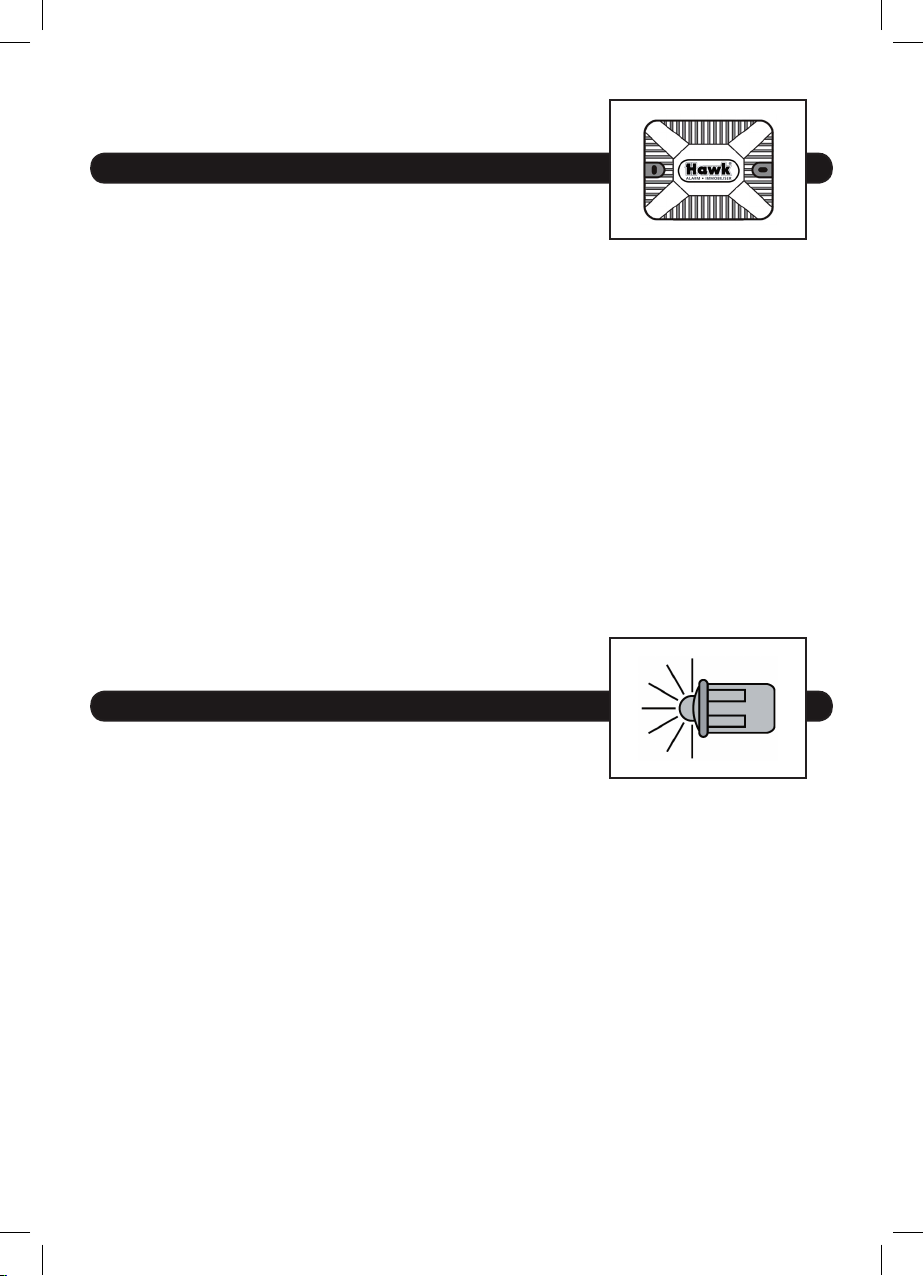
Locaons for the Hawkguard
ultra sonic sensors
Ultrasonic cells should be placed on the le and right side as high as possible so to obtain
the best performance.
Inappropriate adjustment for the Ultrasonic sensor may let to a false alarm. To prevent
the false alarm, make sure the sensibility of ultrasonic sensor is in an appropriate degree.
An over adjustment is usually the main reason to cause false alarm.
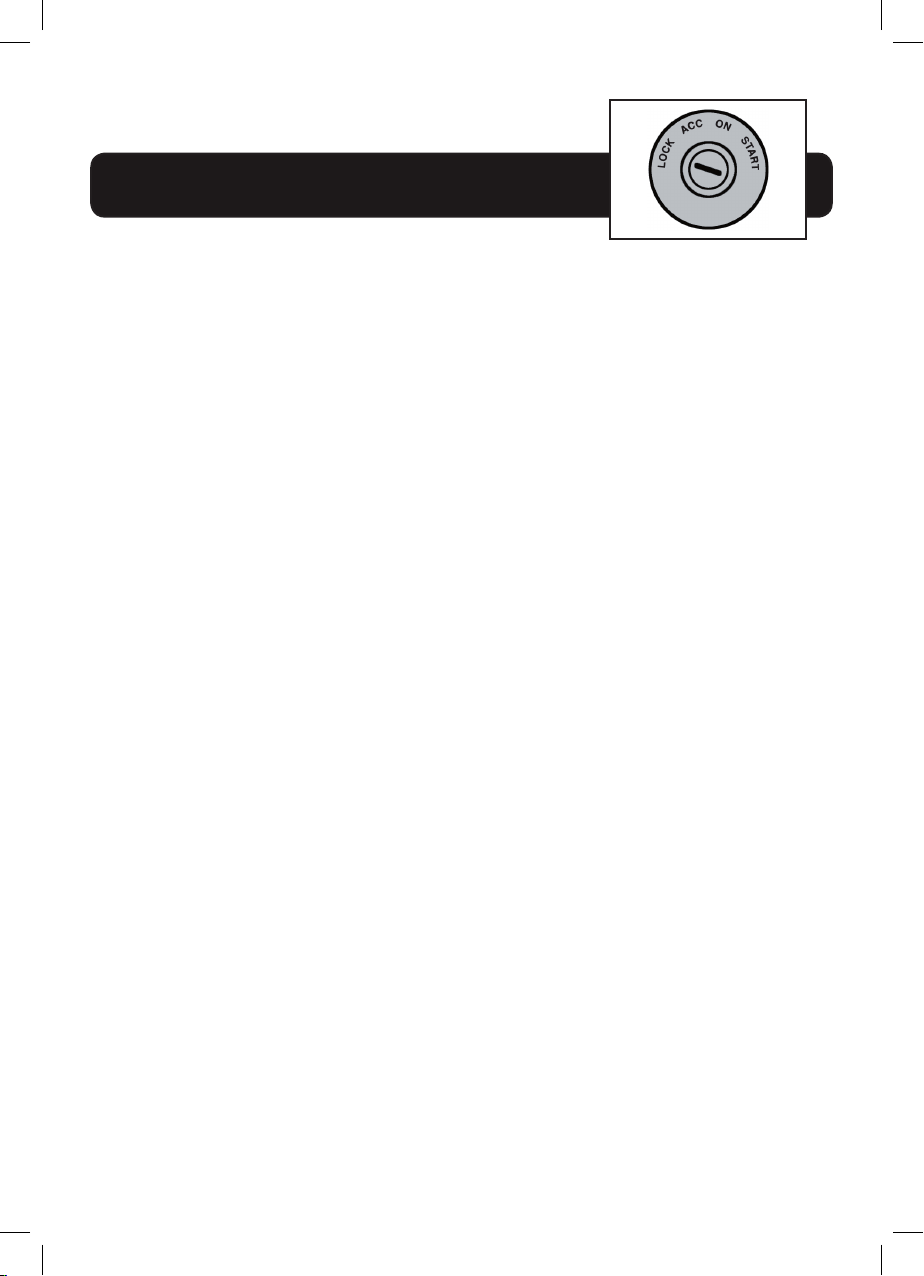
Locaons for the status Immobiliser
If Immobiliser relay or its connecons are immediately
visible upon removal of the underdash panel, they can easily be bypassed. Always make
the relay and its connecons dicult to discern from the factory wiring! Exposed yellow
bu connectors do not look like factory parts, and will not fool anyone! For this reason,
roung the immobiliser relay wires away from the steering column is recommended.
Finding the wires you need
Now that you have decided where each component will be located, you’re going to nd
the wires in the car that the security system will be connected to:
IMPORTANT! Do not use a 12v test light to nd these wires! Use a digital mul-meter for
all tesng.
Obtaining constant 12 volts
We recommend two possible sources for 12v constant:
the (+) terminal of the baery, or the constant supply to the ignion switch. Always
install a fuse within 12 inches of this connecon. If the fuse also will be powering other
circuits, such as door locks, a power window module, headlight control system etc,
fuse accordingly.
IMPORTANT! Do not use a 12v test light to find these wires! Use a digital multi-meter for
all testing.
Ultrasonic cells should be placed on the left and right side as high as possible so to obtain the
best performance.
Inappropriate adjustment for the Ultrasonic sensor may let to a false alarm. To prevent the
false alarm, make sure the sensibility of ultrasonic sensor is in an appropriate degree. An over
adjustment is usually the main reason to cause false alarm.
If Immobiliser relay or its connections are immediately visible upon removal of the under-
dash panel, they can easily be bypassed. Always make the relay and its connections difficult
to discern from the factory wiring! Exposed yellow butt connectors do not look like factory
parts, and will not fool anyone! For this reason, routing the immobiliser relay wires away
from the steering column is recommended.
Finding the wires you need
Now that you have decided where each component will be located, you’re going to find the
wires in the car that the security system will be connected to:
We recommend two possible sources for 12v constant: the (+) terminal of the battery, or
the constant supply to the ignition switch. Always install a fuse within 12 inches of this
connection. If the fuse also will be powering other circuits, such as door locks, a power
window module, headlight control system etc, fuse accordingly.
Obtaining constant 12 volts
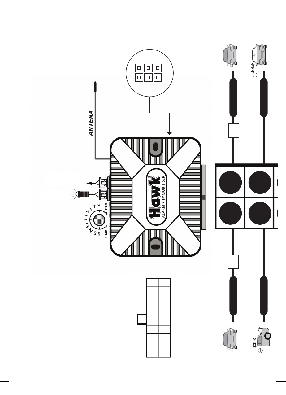
Locations for the immobiliser relay
Locations for the Hawkguard
ultra sonic sensors
N/O COIL COIL N/CCOMMON
5
IMPORTANT! Do not use a 12v test light to find these wires! Use a digital multi-meter for
all testing.
Ultrasonic cells should be placed on the left and right side as high as possible so to obtain the
best performance.
Inappropriate adjustment for the Ultrasonic sensor may let to a false alarm. To prevent the
false alarm, make sure the sensibility of ultrasonic sensor is in an appropriate degree. An over
adjustment is usually the main reason to cause false alarm.
If Immobiliser relay or its connections are immediately visible upon removal of the under-
dash panel, they can easily be bypassed. Always make the relay and its connections difficult
to discern from the factory wiring! Exposed yellow butt connectors do not look like factory
parts, and will not fool anyone! For this reason, routing the immobiliser relay wires away
from the steering column is recommended.
Finding the wires you need
Now that you have decided where each component will be located, you’re going to find the
wires in the car that the security system will be connected to:
We recommend two possible sources for 12v constant: the (+) terminal of the battery, or
the constant supply to the ignition switch. Always install a fuse within 12 inches of this
connection. If the fuse also will be powering other circuits, such as door locks, a power
window module, headlight control system etc, fuse accordingly.
Obtaining constant 12 volts
Locations for the immobiliser relay
Locations for the Hawkguard
ultra sonic sensors
N/O COIL COIL N/CCOMMON
5