Hawk 226-M User manual

Bushton Manufacturing
Maker Of
Hawk Woodworking Tools
---------
MODEL 226-1 1
VARIABLE SPEED
PRECISION
SCROLL SAW
OPERATORS MANUAL
MANUAL CO-0286

TRAINING:
1. Read the operators manual carefully. Be thorough-
ly familiar with the operation of the equipment.
2. Know where the controls are and how to operate
them.
3. Wear safety goggles, ear protection and mask in
dusty operations.
4.
Never allow children to operate equipment. Never
allow adults to operate the equipment without prop-
er instruction.
5. Keep work area clear of other persons.
6. Maintain a clean uncluttered work area.
~
OPERATION SAFETY: ~.
1. Never make any adjustments while the machine is
running.
2. Keep hands and feet away from rotating parts.
3. Disconnect electrical power supply before doing
any adjustments on the machine.
SAFETY
4. Remove all working tools and equipment before
starting machine.
5. Wear proper clothing. Avoid loose fitted clothing,
long sleeves, long hair, gloves, neck ties, jewelry,
watches, rings, etc.
6. Do Not operate an electrial device in a damp or wet
area to avoid electrical shock.
7. Maintain all safety guards.
8. Do not operate machine while under the influence
of medication, alcohol or drugs.
9. Never leave machine running unattended.
10. Don't overload machine. Follow operators instruc-
tion for safe operation.
11. Keep equipment in proper working order. Follow
recommended maintenance procedures in the op-
erators manual.
WARRANTY
We guarantee each Hawk Scroll Saw to be free from defects in material and
workmanship for 1 year from date of delivery to original user. This warranty
does not cover damage sustained in transit or from misuse of this piece of
equipment.
This warranty does not Obligate us to bear the cost of labor, or
transportation charges in connection with the replacement or repair
of defective parts, nor shall it apply to any saw upon which repairs
or alterations have been made unless authorized by us.
We make no warranty in respect to components, not of our manu-
facture, including motors, such being subject to the warranties of
their respective manufacturers.
We shall in no event be liable for consequential damages or contingent
liabilities arising out of the failure of any saw to operate properly.
No express, implied or statutory warranty other than herein set forth
is made or authorized to be made by us.
ENCLOSED WARRANTY REGISTRATION CARD MUST BE RETURNED
TO VALIDATE YOUR WARRANTY.
vvvv vvvvvVVVVvvvvvvvvvvvvvvvvvvvv
/\/\
I<
I<
I<
I<
<
I<
I<
I<
I<
I<
I<
k
I<
k
I<
I<
<:
i<
I<
I<
I<
I<
I<
k
VI/v v v
TO VALIDATE WARRANTY
CUSTOMERS
Must mail in warranty card on receipt of machine.
>
>
>
>
>
>
>
>
>
>
>
>
>
>
s
S
5
~
>
>
>
>

Length Less Legs: 34%
Width Less Legs: 16%
Length Leg at Bottom: 41
Width Leg at Bottom: 24
HAWK 226·M - SPECIFICATIONS
Height With Legs: 45 Maximum Cutting Depth: 2
Table Height With Legs: 29% Stroke Length: 1%
Weight Saw and Stand: 105 pounds Strokes/Minute: 550-1550
Throat: 26 Table Adjustment: OQ..45°Right or Left
Drive: Belt, Manual Variable Speed
SET·UP INSTRUCTIONS
NOTE:
Damages or shorted parts are to be reported to
the transportation carrier.
MANUFACTURER IS NOT
RESPONSIBLE FOR SHIPPING DAMAGE.
V4
CARRIAGE
BOLT-
SAW CARTON
Box 1 Box 2
1. Saw 1. Legs
2. Operators Manual 2. Glides
3. Extra Blades 3. Attaching Hardware
Remove your saw from the shipping carton. Check for
damage (see note above). The four legs come in a separate
carton. Install one leg to each corner of the base using
%
carriage bolts and nuts. Install one
%
nut on each
of the four glides. Insert the glides up through the hole
NOTE:
Optional
Adjustable 6
Leg Extension available.
Part #6LE
LEG--
BASE
%
NUT
GLIDE
in the bottom of the leg and install the second
%
nut
to secure. With the legs secure to the base, set the saw
upright and adjust the nuts on the glides so each glide
supports the saw. Secure (see figure).
BLADE SELECTION (Wood)
All Blades are 5 Long - Order by R.B.I No. (Blade Pitch)
R.B.I. NO. MATERIAL CUT
USAGE WIDTH THICKNESS TPI
2/0 For extremely intricate sawing. Very thin cuts in 1/16 to 3/32 materi- .022 .010
als. Excellent for cutting wood veneer, plastics, hard rubber, pearl. Very
good finish with fast cutting. Excellent for tight radius cuts.
27
2
Fortight radius work in thin materials 3/32 to 1/8 wood veneer, wood,
bone, fiber, ivory, plastic. Good finish, fast cutting tight radius. .029 .012 20
.037 .015 16
.043 .016 14
.053 .018 12
.100 .022
9
with 3
reverse
teeth
5
For close radius cutting in materials 1/8 or thicker. Great for sawing
hard/soft wood, bone, horn, plastics. Good general purpose cutting with
a medium finish.
7 Popular sizes for cutting hard and soft woods 3/16 up to 2 . Also
9 cut plastic, paper, felt, bone. Medium finish may require some sanding.
420-R For smooth splinter-free finish on top and bottom sides. Excellent for
hard/soft wood, plywood with thickness of 1/4 or more. Fast cutting.
METAL CUTTING (FINIS) BLADES
[CAUTION: Must be run on slow speed]
Pitch
#0
#1
#2
#3
#4
#5
#7
T.P.I. Thick
50 .011
46 .012
43 .013
41 .014
38 .015
33 .016
28 .019
Wide
.024
.025
.029
.031
.034
.035
.04W'

OPERATION
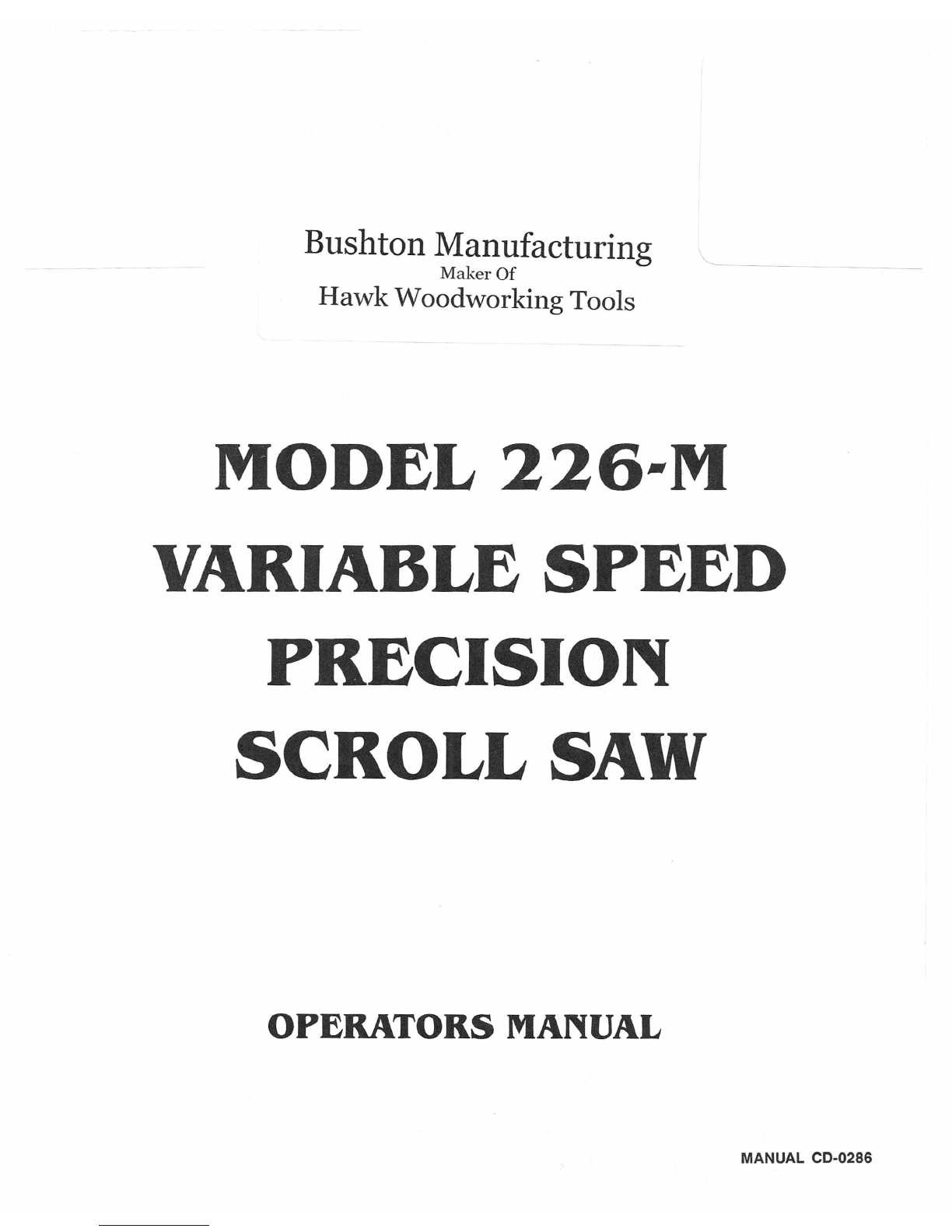
A. Blade installation in the blade holder
Place the blade holder in the oblong slot in the base
(right side of the saw base near the front.) Slide the
bottom of the blade (direction the teeth point) between
the two halves of the holder to the center screw. (Run
your finger across the teeth to determine the direction
the teeth point.) Center and secure using a 5/16 open
end wrench. (See Figure 1)
TOPVIEW SIDE VIEW
BASE
5/'6
OPEN
END WRENCH
f
TABLE
CENTER BLADE
IN HOLDER
FIGURE 1 BLADE HOLDER
1--7---
BLADE
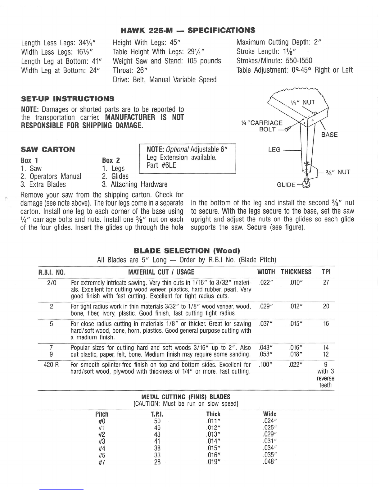
B. Blade installation in the saw (See Figure 2)
Place the quick change holder rod in the slot of the
upper arm behind the quick change blade holder. Slide
the blade up from the bottom thru the hole in the
center of the table. Pull the blade up until the holder
is at the bottom of the lower arm. Slide the blade and
holder back in the lower arm slot until the holder rests
in the V at the bottom of the lower arm between
the arm and clip.
Pull the upper arm down until the upper arm blade
holder assembly will slide over the blade (it may be
necessary to loosen the adjusting handle at the rear
of the saw to allow the upper arm to come down).
Center the blade in the blade holder and slide upward
to the screw. (See Figures 1, 2 & 3)
----------1.- QUICK CHANGE
,..--•.••••••~-. HOLDER ROD
PLACE BLADE INLINE
WITH SCREW
LOOSEN TO INSTALL BLADE FIGURE 2
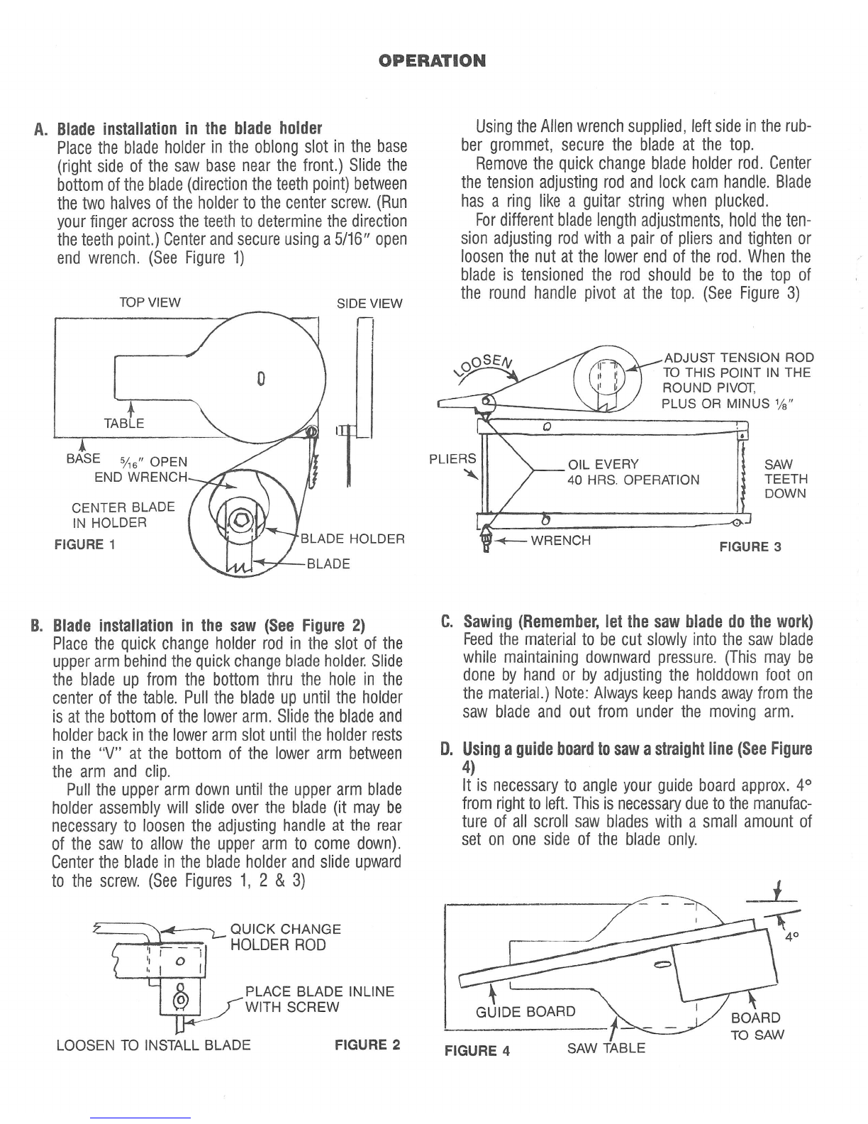
Using the Allen wrench supplied, left side in the rub-
ber grommet, secure the blade at the top.
Remove the quick change blade holder rod. Center
the tension adjusting rod and lock cam handle. Blade
has a ring like a guitar string when plucked.
Fordifferent blade length adjustments, hold the ten-
sion adjusting rod with a pair of pliers and tighten or
loosen the nut at the lower end of the rod. When the
blade is tensioned the rod should be to the top of
the round handle pivot at the top. (See Figure 3)
ADJUST TENSION ROD
TO THIS POINT IN THE
ROUND PIVOT,
PLUS OR MINUS %
SAW
TEETH
DOWN
FIGURE 3
C. Sawing (Remember, let the saw blade do the work)
Feedthe material to be cut slowly into the saw blade
while maintaining downward pressure. (This may be
done by hand or by adjusting the holddown foot on
the material.) Note: Always keep hands away from the
saw blade and out from under the moving arm.
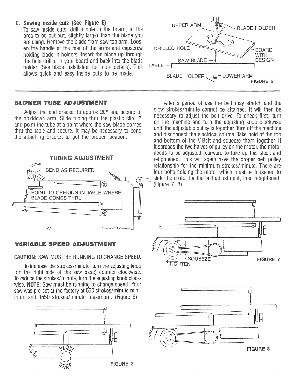
D. Using a guide board to saw a straight line (See Figure
4
It is necessary to angle your guide board approx. 4°
from right to left. This is necessary due to the manufac-
ture of all scroll saw blades with a small amount of
set on one side of the blade only.
BOARD
TO SAW
FIGURE 4

E. Sawing inside cuts (See Figure 5)
To saw inside cuts, drill a hole in the board, in the
area to be cut out, slightly larger than the blade you
are using. Remove the blade from saw top arm. Loos-
en the handle at the rear of the arms and capscrew
holding blade in holders. Insert the blade up through
the hole drilled in your board and back into the blade
holder. (See blade installation for more details). This
allows quick and easy inside cuts to be made.
UPPER ARM~'i~1 ~ BLADE HOLDER
Ii
,
-BOARD
WITH
SAW BLADE - DESIGN
TABLE -
==:~~=:~~:=~=~:==========
BLADE HOLDER
<, ;-
LOWER ARM
J
FIGURE 5
BLOWER TUBE ADJUSTMENT
Adjust the end bracket to approx 20° and secure to
the holddown arm. Slide tubing thru the plastic clip 1
and point the tube at a point where the saw blade comes
thru the table and secure. It may be necessary to bend
the attaching bracket to get the proper location.
TUBING ADJUSTMENT
BEND AS REQUIRED
~---_--1@
L=.._--,
- POINT TO OPENING IN TABLE WHERE
BLADE COMES THRU
VARIABLE SPEED ADJUSTMENT
CAUTION:
SAW MUST BE RUNNINGTOCHANGESPEED.
Toincreasethe strokes/minute, turn the adjusting knob
(on the right side of the saw base) counter clockwise.
Toreducethe strokes/minute, turn the adjusting knob clock-
wise.
NOTE:
Saw must be running to change speed. Your
saw was pre-set at the factory at 550 strokes/minute mini-
mum and 1550 strokes/minute maximum. (Figure 6)
e
FIGURE 6
After a period of use the belt may stretch and the
slow strokes/minute cannot be attained. It will then be
necessary to adjust the belt drive. To check first, turn
on the machine and turn the adjusting knob clockwise
until the adjustable pulley is together. Turn off the machine
and disconnect the electrical source. Takehold of the top
and bottom of the V-Belt and squeeze them together. If
it spreads the two halves of pulley on the motor, the motor
needs to be adjusted rearward to take up this slack and
retightened. This will again have the proper belt pulley
relationship for the minimum strokes/minute. There are
four bolts holding the motor which must be loosened to
slide the motor for the belt adjustment, then retightened.
(Figure 7, 8)
+=-=
SQUEEZE
TIGHTEN FIGURE
FIGURE
8

226·M PARTS BREAKDOWN
Part
#
QUANT. PART
#
QUANT.
1. RB-107 10-32 Hex Nut. 248. ES-41 %-20 X
%
Carriage Bolt 2
2. ES-81 Clamp 249. HA-65 Quick Change Hold Rod 1
3. CD-35 Tubing 150. HA-16 Rubber Grommet 4
4. ES-08 Shaft (Foot to arm) 151. CD-34 Serial Tag 1
5. ES-10 Foot Seat Pod 152. FA-12 #7 Drive Screw 2
6. RB-106 Machine Screw 153. ES-86
%4
I
'T Allen Wrench 1
7. RZ-83 %-20 X %
S/S
554. HA-63 Cable Clamp 1
8. ES-09 Foot 155. HA-61 Switch 1
9. FA-40 Arm insert 156. HA-60 Cord Set 1
10. ES-35 10-32 X % 157. RB-99 %-20 X
%
Carriage Bolt 13
11. FA-41 Blade Holder (Side) 158. CD-29 Base 1
12. FA-43 Roll pin
%
X % 159. HA-24 Rubber Bellows 1
13. FA-42 Roll Pin
%
X
%
Lg 160. HA-25 Bellows Holddown Bracket 1
14. ES-40 Knob 161. HA-14 Spacer 3
15. RB-150
5;16
F W
562. HA-13 Shoulder Bolt
1
16. CD-36 Spacer 463. HA-69 Pitman 1
17. PS-07 Brg 10 64. HA-68 %-13 Nut 1
18. HA-77 Round handle pivot 165. ES-57 Glides (4) with (8) Nuts 1
19. CD-31 Handle 166. CD-07 Leg 4
20. HA-75 Connector Rod Pivot 267. HA-55 Motor 1140 R.P.M. 1
21. FA-36 Spring 168. RZ-179
5;16
X
%
Carriage 4
22. HA-78 %-20 Neoprene insert nut 169. HA-58
VIS
Sheave Spring 1
23. HA-80 Rod 170. ES-12-Z Pitman Shaft 1
24. HA-71 Shoulder bolt 271. ES-15 Collar 3
25. CD-02 L.H. Arm Support 172. ES-96 Cover 1
26. CD-03 R.H. Arm Support 173. RBZ-211 %-20 X 1% Carriage 2
27. PS-52 %-20 X 1 Hex Hd. Bolt 10 74. ES-95 Housing Weldment 1
28. RB-177 %
F W
14 75. ES-97 Shaft 1
29. RZ-178
5;16
L/W 576. ES-92 Gear 2
30. RZ-181
5;16
X 1 % Hex Hd. Bolt 177. ES-35 10-32 X % Socket Hd. Cap Screw 8
31. CD-05 Lower Arm
1
78. CD-33 Counter Wt. 2
32. CD-13 Rear Table Support 179. HA-56
VIS
Pulley Manual 1
33. CD-30 Base Reinforcement 180. HA-57
VIS
Control Assy 1
34. RB-517 Spacer Slide Nylon 181. FA-35 10-32 X % Rd Hd Slotted Screw 1
35. CD-01 Table 182. HA-29 Pointer 1
36. RZ-182 % Socket Flat Head
%
Lg 283. HA-31 Stop 1
37. HA-20 Table tilt table bracket 184. HA-32 Screw 1
38. HA-33 Screw 385. HA-21 Table tilt base bracket 1
39. ES-49 %-28 Hex Nut 286. FA-08
%
Nut neoprene insert 2
40. HA-36 Washer 187. CD-04 Top Arm 1
41. ES-42 Knob Table Tilt 1
88.
CD-06 Holddown Arm 1
42. RB-223 % Whiz Nut 17 89. RBZ-207 % L/W 11
43. ES-22 Blade Holders 290. PS-80 %-20 X 1
%
Hex Hd Bolt 2
44. ES-68 %-20 X
%
Allen Hd
S S
1
91.
HA-67 Spacer
4
45. RZ-81
5;16
Hex Nut 492. RB-112 Rivit Burr 8
46. ES-65 Saw Blade Holder 193. HA-59 Belt 2200 1
47. RB-150
5;16
F W
494. HA-73 %-20 X 2 Hex Hd Bolt 2


MAINTENANCE
TABLE -
Keep the table work surface waxed to prevent rust and allow easier movement of the wood on the table surface.
TENSIONING ROD -
Add 1 or 2 drops of oil (light machine oil) to the blade tensioning rod pivots at the arms.
PROBLEM
TROUBLE SHOOTING GUIDE
POSSIBLE CAUSE POSSIBLE SOLUTION
SELECT PROPER BLADE SIZE
EXCESSIVE BLADE BREAKAGE IMPROPER BLADE SIZE TO
WOOD THICKNESS
CUTTING TOO TIGHT OF A
RADIUS FOR BLADE SIZE
IMPROPER BLADE INSTALLATION
INCREASE RADIUS SIZE OR
REDUCE BLADE SIZE
INSTALL BLADE PROPERLY, SEE BLADE INSTALLATION
BLADE BURNS THE WOOD WRONG BLADE SIZE
CUTTING TOO SMALL A RADIUS
IMPROPER FEEDING
PUSHING SIDE WAYS ON THE BLADE
FEEDING TOO FAST
IMPROPER BLADE TENSION
INCREASE BLADE SIZE
INCREASE RADIUS OR DECREASE BLADE SIZE
FEED MATERIAL AT 4° R. TO L.
FEED STRAIGHT SO AS NOT TO BEND BLADE L. OR R.
REDUCE FEED RATE
INCREASE BLADE TENSION
BLADES BEND BACK
EXCESSIVELY OR TWISTS
WHILE SAWING
IMPROPER BLADE TENSION
IMPROPER BLADE SIZE
FEEDING TOO FAST
INCREASE BLADE TENSION
INCREASE BLADE SIZE
SLOW FEED RATE
BLADE CUTTING TOO LARGE
A RADIUS BLADE TOO LARGE
BLADE TENSION LOW
IMPROPER FEEDING
USE SMALLER BLADE
INCREASE BLADE TENSION
TURN BOARD PROPERLY
BOARD SPLINTERING ON
THE
BOTTOM WRONG BLADE SIZE
WOOD GRAIN STRINGY OR KNOTTY USE SMALLER BLADE
USE MASKING TAPE ON THE
BOTTOM AT THE SAW LINE
ROUGH CUT ON THE
SAWED EDGE BLADE TOO LARGE
BLADE TENSION LOW
POOR QUALITY WOOD
FEEDING TOO FAST
USE SMALLER BLADE
INCREASE BLADE TENSION
USE BETTER QUALITY WOOD
SLOW FEED RATE
BLADE DOESN'T FOLLOW
PATTERN LINE PRACTICE
IMPROPER FEEDING (FEED AT AN
ANGLE R. TO L. OF APPROX 4°
STRAIGHT INTO THE BLADE
BLADE DULL
BLADE TOO SMALL
IMPROPER BLADE TENSION
FORCING MATERIAL INTO THE
BLADE
REPLACE BLADE
INCREASE BLADE SIZE
INCREASE TENSION
WOOD JUMPS ON THE
TABLE
REDUCE FEED SPEED
IMPROPER HOLDDOWN ADJUSTMENT
BLADE INSTALLED UPSIDE DOWN
TURNING TOO TIGHT OF A RADIUS
NOT USING HOLDDOWN AND NOT
HOLDING BOARD DOWN FIRMLY
SAWING TOO FAST
PRESSING SIDEWAYS ON THE BLADE
ADJUST THE HOLDDOWN TO APPLY PRESSURE TO
THE BOARD.
INSTALL BLADE PROPERLY TEETH POINTING DOWN
INCREASE RADIUS SIZE
HOLD BOARD FIRMLY ON THE TABLE ESPECIALLY
WHEN TURNING FEED PROPERLY (FEED AT AN ANGLE
R. TO L. OF APPROX. 4°
&
STRAIGHT INTO THE
BLADE.)
REDUCE FEED SPEED
FEED AT
4°
ANGLE R. TO L. AND STRAIGHT
Table of contents
Other Hawk Saw manuals
Popular Saw manuals by other brands

Red Stone
Red Stone MT100 Translation of original instruction manual

CO/Tech
CO/Tech J1X-KZ2-210-UK instruction manual

woodmizer
woodmizer LT70HD Safety, Setup, Operation & Maintenance Manual

woodmizer
woodmizer LX450DB-A Safety, Installation, Operation, Maintenance & Parts Manual

CO/Tech
CO/Tech HF-ZJ-0101 Original instructions

BLACK DECKER
BLACK DECKER BDCMTTS instruction manual