Hawle 245-02 Manual

01/2018 Subject to change
Page 1 of 3
Operating and maintenance instructions for
Universal Hawlinger for later drilling with vertical and horizontal
ZAK® outlet 90° to pipe direction
Order No. 245-02
1. Intended use/Product description
Medium: Potable Water
Max. operating pressure: 16 bar
Material:
Body: GJS-400, Hawle epoxy powder coating
Spindle, shut-off device, shut-off blade: stainless steel
Gaskets: EPDM acc. to DVGW-worksheet 270
Universal-Hawlinger for later drilling are to be used for installation on cast iron, steel and AC pipes from DN65 - DN
500. Adjusting to the main pipe is achieved by means of retaining strap and saddle gasket (Order No. 310 or Order
No. 311) in the corresponding nominal width.
Type „NA“ Hawlinger®are used for the later drilling of previously installed service connections. The stringent de-
mands on hygiene, in particular the requirements of DIN 1988 (avoidance of dead water zones), are thus consistently
implemented. Subsequent excavation for drilling the main pipeline when commissioning the service connection is not
necessary with this system.
The horizontal ZAK® outlet is used, in combination with ttings, for the connection of house service pipes.
We recommend the use of our surface box Order No. 212 for later drilling via the drilling conduit and for actuating the
extension spindle.
During installation and maintenance operations, the applicable standards and guidelines, accident prevention regu-
lations and the regulations of professional associations are to be observed and complied with.
Installation and maintenance operations should only be carried out by qualified personnel.
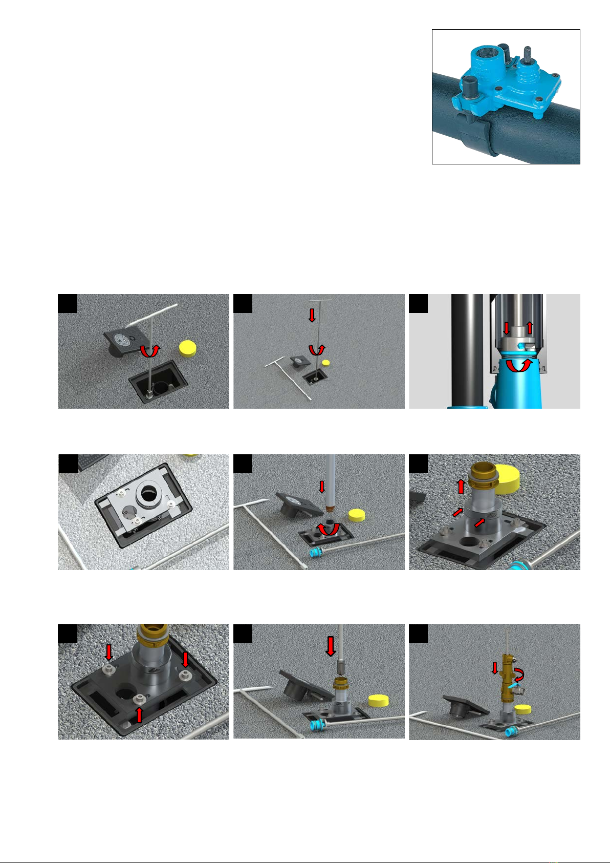
2. Installation
2.1 Installing the pipe drilling saddle
1. Procedure for metallic pipes with sheathing in the area of the pipe drilling saddle
The DVGW leaet W333, Pipe Drilling Saddles and Drilling Procedure in Water Supply/9.2.2. Pipe Sheathing for
Metal Pipes must be observed.
PE sheathing: The PE sheathing on pipes according to DIN 30674-1 remains on the pipe providing there is sufcient
adhesion.
Cement mortar (CM) sheathing: The additional cement mortar sheathing on a PE-coated pipeline should be removed
in the area of the pipe drilling saddle, unless the borehole wall is sealed by suitable means.
The CM sheathing on cast iron pipes according to DIN 30672-2 also remains on the pipe, if it complies with Plastics
and Drinking Water (KTW) quality standards and provided that there is sufcient adhesion and surface smoothness
as well as low mortar porosity in the area of the pipe drilling saddle.
When removing protective sleeves, the unprotected pipe area between clamping bracket, service valve and PE/CM
sheathing must be protected after installing the pipe drilling saddle by means of secondary sheathing measures in
accordance with the raw material manufacturer‘s recommendations (e.g. suitable winding tape or shrink hose solu-
tions).
These instructions apply unless the pipe manufacturers expressly recommend otherwise for their sheathed pipes.
1: Universal-Hawlinger ZAK
2: ZAK-plug
3: Strap
4: PE-guide pipe
5: Aluminium pipe support
6: Pipe protection cap
7: Telescopic extension spindle (pipe cover
depth 1,30 - 2,00 m)
8: Base plate
9: Surface box
10: Pipe retaining clips
Important: Items 3, 8 and 9 are not included in
the scope of delivery!

01/2018 Subject to change
Page 2 of 3
2. Free the surface of the pipe of any dirt, soil or grease.
3. Fit the service valve.
4. Hook the bracket on one side of the saddle body and bend it around the pipe.
5. Fit the second clamping jaw.
6. Tighten the hexagon head screws with the specied torque (60 - 70 Nm / max.
100 Nm) alternately and evenly. Do not use an extension!
7. To adjust the pipe drilling saddle to the required pipe cover depth
- Remove the pipe retaining clips, item no. 10, and the pipe protection cap, item
no. 6, to shorten
- Shorten the protection pipe
- Ret the pipe retaining clips, item no. 10 and the pipe protection cap, item no.6
8. Establish house connection
9. Perform leak test according to DVGW guidelines.
Note:
When applying the bituminous base course, the protection pipe and the extension spindle must be protected against
thermal impact.
2.2 Installation procedure
1
Remove the surface box cover. Take off the pi-
pe protection cap. Open Hawlinger by turning to
the left using the valve key.
2
Remove the ZAK plug. For this purpose insert
plug key into the standpipe and turn until
the locking lugs engage.
Press the key down firmly countering the resi-
stance of the spring and friction. Then turn to
the left until stop and withdraw the plug.
3
4
5
6
Insert clamping unit into the box frame and po-
sition centrally above the standpipe.
Insert the drilling pipe through the clamping unit
into the standpipe. Push the drilling tube into the
ZAK outlet of the Hawlinger and turn clockwise
(90°) to lock.
Pull the drilling pipe upwards to prevent it from
being inadvertently unlocked, and clamp it by
tightening the hexagon socket screws (M8).
7 9
8
Secure the position of the clamping unit by tigh-
tening the hexagon socket screws (M10).
Slide the drill rod* up to the pipe surface. Slide the drilling device over the drill rod and
screw onto the threaded adapter.
* When utilising the Hawle „Hawlomat“ drilling device, drill rod L = 1,800 mm, Oder No. 831 900 0002, and drill rod extension, Order No. 831 200 1050,
must be used.

01/2018 Subject to change
Page 3 of 3
10 11 12
Connect the drill rod to the drilling device by
tightening the clamping screw. Attach the flus-
hing hose to the drilling device and move the
flushing valve to the open position.
Place a suitable drive (ratchet, electric, etc.) on
the drill rod and drill with feed. Follow the drilling
instructions of the drilling device.
Slowly loosen the clamping screw of the drill rod
on the drilling device and pull the drill rod up-
wards. Caution: The drill rod can travel upwards
at high speed if the system pressure is high
enough. Apply manual fore to counteract, and
ensure that the head is out of the danger zone.
18
13 14 15
Flush any residual swarf from the drilling area
and close the flushing valve. Then close the
Hawlinger using a valve key above the exten-
sion spindle by turning it clockwise until stop.
Remove the flushing hose from the drilling unit,
unscrew the drilling unit and pull out the drill.
Loosen the clamping screw (M8) on the clamp.
Press the drilling pipe downwards and unlock
by turning anticlockwise (90°), and remove it
along with the clamping unit.
Empty the standpipe and Hawlinger using a sui-
table suction device.
1716
Insert the ZAK plug with key into the Hawlinger
socket, press downwards and lock by turning
clockwise (90°). Then secure the unlocking me-
chanism by lifting the key.
Check the unlocking safety mechanism without
compression and tensile load on key and ZAK
plug by turning anticlockwise.
Fit the pipe protection cap one by one. Fit the
surface box cover.
3. Maintenance
Hawlinger for later drilling are maintenance-free.
4. Commissioning/Pressure test
After successful installation, a pressure test must be carried out in accordance with DVGW regulations.
If you have any other questions or if you need more information please contact:
Hawle Armaturen GmbH
- Application Engineering -
Liegnitzer Str. 6
83395 Freilassing
Phone: +49 (0)8654 6303-0
Telefax: +49 (0)8654 6303-222
E-Mail: [email protected]
Web: www.hawle.de
Popular Drill manuals by other brands

EINHELL Bavaria
EINHELL Bavaria BBH 850/1 operating instructions

Milwaukee
Milwaukee M18 FUEL 2804-20 Operator's manual

Jiffy
Jiffy LECTRIC STX PROII Operating manual/parts guide

Tailift
Tailift TPR720A Operation manual

Metabo
Metabo KHE 5-40 operating instructions

Power Stroke
Power Stroke PSL0DD181 Operator's manual