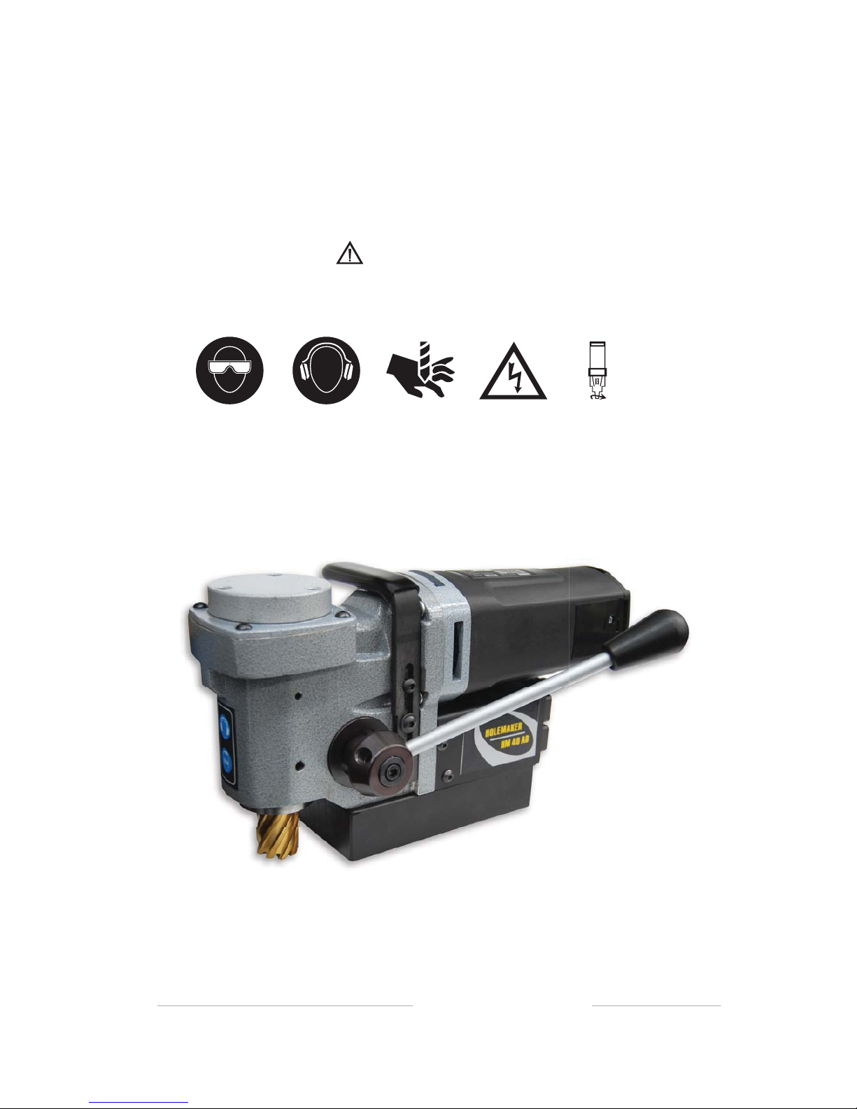
Holemaker Portable Magnetic Drilling Machine
Congratulations on your purchase of a Holemaker portable magnetic drilling machine. Holemaker drilling machines
are designed to deliver fast, efficient hole drilling performance in portable applications.
TABLE OF CONTENTS
Important Safety Instructions . . . . . . . . . . . . . . . . . . . . . . . . . . . . . . . . . . .3-4
Grounding Instructions and Extension Cords . . . . . . . . . . . . . . . . . . . . . . . . .5
Special Instructions . . . . . . . . . . . . . . . . . . . . . . . . . . . . . . . . . . . . . . . . . . . .6
Contents of Package . . . . . . . . . . . . . . . . . . . . . . . . . . . . . . . . . . . . . . . . . . .6
Getting Started . . . . . . . . . . . . . . . . . . . . . . . . . . . . . . . . . . . . . . . . . . . . . . . .6
Machine Operation . . . . . . . . . . . . . . . . . . . . . . . . . . . . . . . . . . . . . . . . . . . . .7
Basic Troubleshooting . . . . . . . . . . . . . . . . . . . . . . . . . . . . . . . . . . . . . . . . . .8
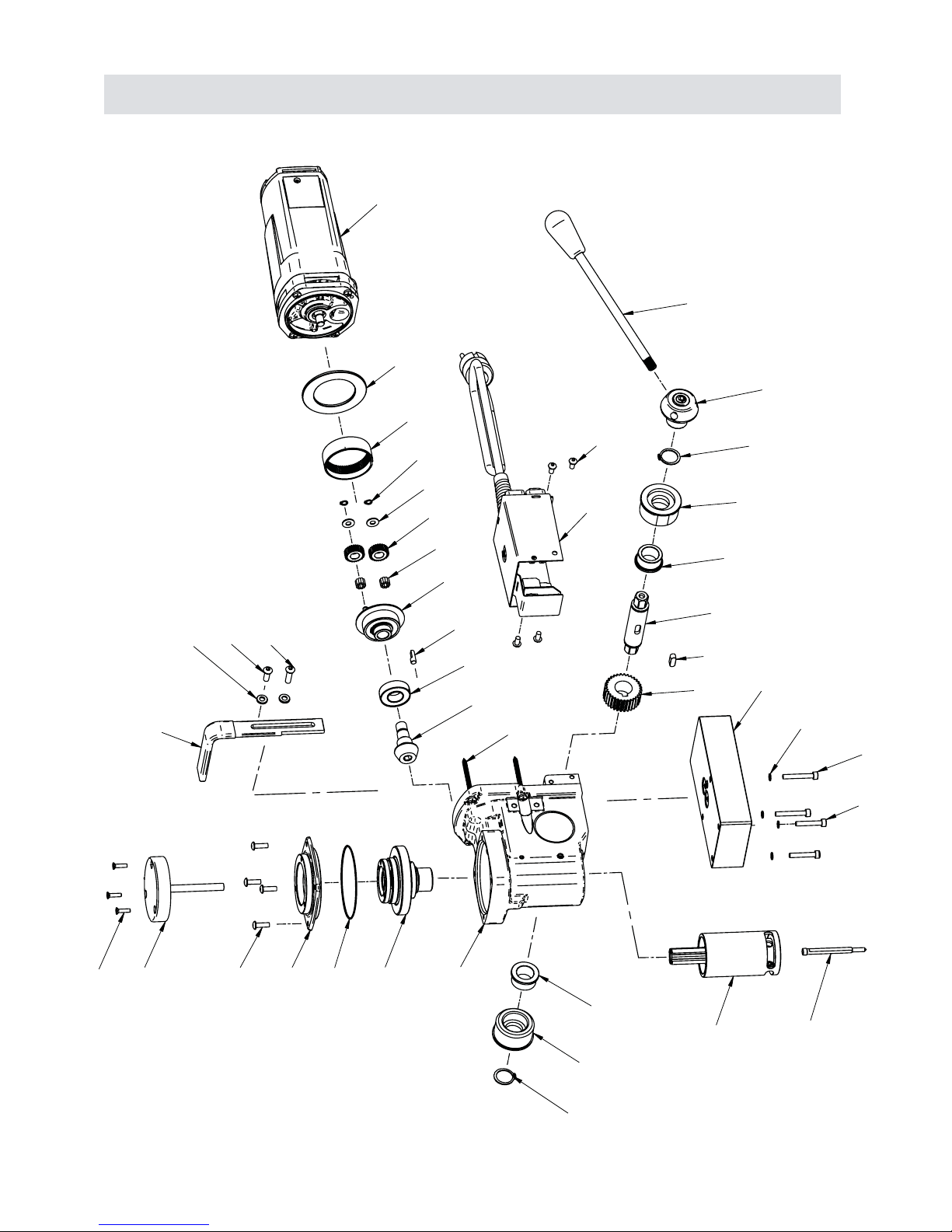
Machine Breakdown . . . . . . . . . . . . . . . . . . . . . . . . . . . . . . . . . . . . . . . . . .9-19
LIMITED WARRANTY
Industrial Tool & Machinery Sales (hereinafter refered to as ITMS) will, within twelve (12) months from the original
date of purchase, repair or replace any goods found to be defective in materials or workmanship.
This warranty is void if the item has been damaged by accident, neglect, improper service or other causes not
arising out of defects in materials or workmanship. This warranty does not apply to machines and/or components
which have been altered, changed, or modified in any way, or subjected to use beyond recommended capacities and
specifications. Electrical components are subject to respective manufacturers’ warranties.All goods returned defective
shall be returned prepaid freight to ITMS or agreed repair agent, which shall be the buyer’s sole and exclusive
remedy for defective goods. ITMS accepts no additional liability pursuant to this guarantee for the costs of travelling
or transportation of the product or parts to and from ITMS or the service agent or dealer, such costs are not included
in this warranty.
Our goods come with guarantees which cannot be excluded under the Australian Consumer Law. You are entitled
to replacement or refund for a major failure and to compensation for other reasonably foreseeable loss or damage.
You are also entitled to have the goods repaired or replaced if the goods fail to be of acceptable quality and the
failure does not amount to a major failure.
THE MANUFACTURER RESERVES THE RIGHT TO MAKE
IMPROVEMENTS AND MODIFICATIONS TO DESIGN WITHOUT PRIOR NOTICE.
2
Height 181mm
Width 189mm
Length (inc. Handle) 327mm
Weight 11.1kg
Power 1080W
240V / 5.1A
400RPM
Arbor Bore 19mm
DIMENSIONS & SPECIFICATIONS
Magnetic Base Dimensions 80mm x 160mm
Magnetic Dead Lift 9500nm on 25mm Plate
Cutter Diameter (Maximum) 40mm (1¾")
Depth Of Cut (Maximum) 25mm (1")