Haws SP157.15 Guide

03/21 Model SP157.15 Page 1 of 8
1455 Kleppe Lane Sparks, NV 89431-6467 (775) 359-4712 Fax (775) 359-7424
No. 0510001072 (2)
Model SP157.15
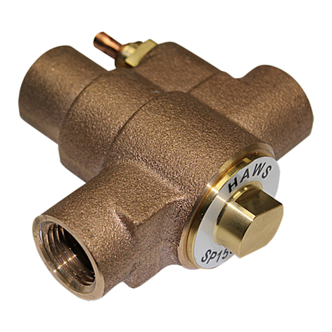
Scald Protection Bleed Valve
INSTALLATION, OPERATION
&
MAINTENANCE INSTRUCTIONS
LIMITED WARRANTY
HAWS warrants that this specific product is guaranteed against defective material or poor workmanship for
a period of one year from date of shipment. HAWS liability under this warranty shall be discharged by
furnishing without charge F.O.B. HAWS Factory any goods, or part thereof, which shall appear to the
Company upon inspection to be of defective material or not of first class workmanship, provided that claim
is made in writing to Haws within a reasonable period after receipt of the product. Where claims for defects
are made, the defective part or parts shall be delivered to the Company, prepaid, for inspection. HAWS will
not be liable for the cost of repairs, alterations or replacements, or for any expense connected therewith
made by the owner or his agents, except upon written authority from HAWS, Sparks, Nevada. HAWS will
not be liable for any damages caused by defective materials or poor workmanship, except for
replacements, as provided above. Buyer agrees that Haws has made no other warranties either expressed
or implied in addition to those above stated, except that of title with respect to any of the products or
equipment sold hereunder and that HAWS shall not be liable for general, special, or consequential
damages claimed to arise under the contract of sale.
The emergency equipment manufactured by HAWS is warranted to function if installation and maintenance
instructions provided are adhered to. The units also must be used for the purpose for which they were
intended. This product is intended to supplement first-aid treatment. Due to widely varying conditions,
Haws cannot guarantee that the use of this emergency equipment will prevent serious injury or the
aggravation of existing or prior injuries.
NO OTHER WARRANTIES EXPRESSED OR IMPLIED ARE AUTHORIZED, PROVIDED OR
GIVEN BY HAWS.
NOTE TO INSTALLER: Please leave this information with the Maintenance Department.
SHOULD YOU EXPERIENCE DIFFICULTY WITH THE INSTALLATION OF THIS MODEL,
PLEASE CALL:
1-800-766-5612
FOR PARTS CALL: 1-800-640-4297

03/21 Model SP157A.15 Page 2 of 8
*The Model SP157A valve is designed to discharge water warmer than 98°F, which helps to prevent the water from
exceeding the high limit of 100°F specified in ANSI Z358.1. This limit was established by ANSI as the maximum
temperature recommended to avoid potential eye damage during a mandated 15-minute flush period. This is, by design,
a lower temperature than may be commonly considered “scalding” by contact with external skin surfaces.
LOCATION OF UNIT:
•The Model SP157.15 Scald Valve Protection Bleed Valve is intended for use only with the 8315CTFP series of
emergency showers.
•For a scald valve for use with other showers and eyewashes, please see Model 8901B or 8901RFK.
ACTUATION TEMPERATURES:
•Valve begins to open at: 98°F (37°C)
•Valve is fully open at: 105°F (41°C)
•Valve will be fully re-closed at: 95°F (35°C)
Once opened, the valve will discharge water warmer than 95° F (35°C). To stop flow completely, the valve must be
cooled below 95°F (35°C).
RECOMMENDED TOOLS AND SUPPLIES:
•Wire cutters
•Pipe wrench (both smooth-jawed and toothed, if possible)
•Tubing cutter (or similar means to cut through soft 11/16”OD tubing)
•Pipe joint sealant (Loctite PST #567 recommended)
INSTALLATION NOTES:
•Protect the valve with a y-strainer (20 mesh or finer) in the supply line. Scald protection* is lost when the valve is
plugged or fouled; damage may occur. Flush lines before installing.
•Tubing, hosing, or piping is not supplied for the outlet of the valve beyond the shower drain tubing but may be
used in order to direct the flow as desired. Ensure that any outlet plumbing is suitable for the high temperatures
of the water that will pass through it.

03/21 Model SP157A Page 3 of 8
Installation
STEP 1: Unboxing
The following components are included with this model. Pertinent installation steps are included for reference.
•Scald valve assembly......................................Step 3
•Barbed tubing tee............................................Step 4
•Clear drain tubing piece..................................Step 4
•Insulation tube................................................Step 5
•3 zip ties for insulation....................................Step 5
STEP 2: Plumbing Preparation
a) Remove the small piece of insulation from the underside of the inlet plumbing within the shower jacket, by
clipping the zip tie holding the insulation in place.
b) Once this insulation is removed, a galvanized plug will be visible, with heat trace cable running along it.
Pull this heat trace forward so it can rest along the side of the port, then remove and discard the plug.
Installation Tip: It is easiest to install this assembly while installing the 8315CTFP-series shower itself;
refer to the 8315CTFP O&M for details.
If this assembly is to be retrofitted into a completed shower, the lowermost jacketing, as well as the
right-hand section of jacketing at the level of the eyewash, must be removed:
•Peel the black seal trim off of the jacketing flanges, on the jacket segments in and below this area.
•Remove the eyewash push flag and the shower handle assembly so the jacket can slide off.

03/21 Model SP157A.15 Page 4 of 8
STEP 3: Valve
a) Connect and seal the scald valve assembly (use only the obvious wrench flats), orienting the outlet
elbow so that it effectively rests against the insulation. If a length of heat trace is running up the side of this
insulation, make sure that it stays behind the scald valve elbow and tubing.
b) Push the short length of clear tubing fully onto the barb of the outlet elbow.
c) Make sure the shower jacketing in this area will fit fully over this new scald valve assembly. If necessary,
put the jacket in place and
make sure all the edges
can easily touch the
mating jacket edges.
Adjust the angle of the
scald valve assembly as
needed.
d) Pull the shower’s clear
drain tubing out from
between the shower
plumbing and the shower
jacket and place it
temporarily so it is
touching the end of the
short tubing length.
e) Cut the shower’s drain
tubing where it meets the
centerline of the short
tubing.
STEP 4: Drain Tubing
a) Pressurize the shower and check for leaks.
b) Push the end of the drain tubing which
was just cut fully onto the bottom barb
of the barbed tubing tee. Push the new
end of the upper drain tubing fully onto
the top barb. Finally, push the end of
the short length from Step 2 fully onto
the side barb.
WARNING:
Make sure this new drain tubing
assembly is oriented such that both
the shower drainage and the scald
valve drainage can exit the tubing
without pooling.
Make sure the drain tubing is situated
such that it ends below the jacketing
and does not get kinked or pinched at
any point between the jacketing and
the insulated plumbing when the
jacketing is installed.

03/21 Model SP157A Page 5 of 8
STEP 5: Insulation
a) Place the insulation around the scald valve, with the radiused end pointing upward and around the inlet
plumbing insulation.
b) Use both the integral adhesive strips on the insulation to close it up.
c) Use the zip ties to further secure the new piece. Tighten each zip tie only enough to close the insulation
around the plumbing.
CLEANING INSTRUCTIONS:
1. Safely perform any required steps to release water pressure from the shower system.
2. Remove the valve and take it to a faucet with clean hot running water.
3. Use a pair of adjustable pliers (or other suitable device) to hold the valve under hot (not to exceed
140°F) running water for several minutes, turning the valve all around to distribute the heat.
4. Occasionally direct the flow into either end of the valve, until the thermostat opens, and the valve
allows flow through it.
5. While the valve is warmed and open, direct flow through the valve in both directions and observe any
debris (hair, PTFE tape, rust, debris, etc.) that may exit the valve. If no water can be observed flowing
through the valve after 10 minutes of sustained warming above 110°F, the valve may be defective and
require replacement.
6. Cool the valve by running cold water over and through the valve until the valve closes and no flow can
be observed running through the valve.
7. Safely return the valve to service and check for unexpected leaking.

03/21 Model SP157A.15 Page 6 of 8
TROUBLESHOOTING
PROBLEM
REPAIR CHECKLIST
1.
Valve drips continuously
regardless of temperature.
1a.
Debris is likely caught between the plug and seal, or the
seal is damaged. See Cleaning Instructions above to
attempt to remove debris.
b.
Replace the valve.
2.
Valve dribbles unexpectedly.
2a.
Review Actuation Temperatures above carefully, then use
a thermometer to measure the temperature of the water
draining from the valve. If the water draining from the valve
is at or above approximately 95°F, the valve is operating
properly and will shut off when the temperature of the water
in the pipe drops below 95°F.
b.
Replace the valve.
3.
Valve does not open
regardless of suspected hot
water temperature.
3a.
The mechanical thermostat in this valve is simple and
robust, so such thermostat failures are rare but possible.
Confirm there is flowing water pressure to the valve inlet (y-
strainer or some other component upstream is not clogged
or turned off).
b.
See Cleaning Instructions above to attempt to remove
debris.
c.
Replace the valve.
4.
Valve is plugging or fouling
easily.
4a.
Follow Cleaning Instructions above and install a mesh
strainer (20-mesh or finer) or an equivalent particulate filter
upstream of the valve.
b.
Consider removing the valve and installing it backwards.
This will help minimize plugging and fouling issues.
NOTE: This will change the function of the valve such that
it opens based on ambient temperature, rather than water
temperature. This may cause the valve to open more
frequently in hot climates.
WARNING: If the conditions of your installation allow for
the possibility that the water can overheat for reasons other
than ambient heat, reversing the valve in this manner is
NOT recommended.
c.
Replace the valve.
2021 Haws®Corporation –All Rights Reserved
HAWS® and other trademarks usedin these materials are the exclusive property of Haws Corporation.

1
PARTS BREAKDOWN
ITEM
DESCRIPTION
PART NO.
1
SCALD PROTECTION BLEED VALVE
(VALVE ONLY)
SP157A
THIS DOCUMENT IS TRUE AND CORRECT AT TIME OF PUBLICATION. CONTINUED PRODUCT
IMPROVEMENTS MAKE SPECIFICATIONS AND MEASUREMENTS SUBJECT TO CHANGE WITHOUT NOTICE.
APPROVED:
DRAWN:
PART NUMBER
SCALE:
REVISION
JL
09/17/20
2
SP157.15 - SCALD PROTECTION BLEED VALVE
1:2
FV
03/31/21
DRAWING TYPE:
SIZE: A
5578
BY:
DP
PARTS BREAKDOWN
DATE:
DATE:
REV. ECN:
5660
CHK'D.:
MODEL(S)
1455 KLEPPE LANE
SPARKS, NEVADA 89431
(775) 359-4712 FAX (775) 359-7424
E-MAIL: [email protected]
WEBSITE: WWW.HAWSCO.COM
FV
ECN:
WHEN ORDERING PARTS, PLEASE
SPECIFY PART NUMBER
SHEET 1 OF 1
0510001072
© 2021 Haws Corporation - All Rights Reserved.
HAWS® and other trademarks used in these materials are the exclusive property of Haws Corporation.
PAGE 7 OF 8

INLET,
1-1/4" MALE
NPT
OUTLET,
BARB FOR
1/2" ID TUBING
FLOW
8315CTFP SHOWER (SOLD SEPARATELY)
(SP157.15 INSULATION & CERTAIN
SHOWER COMPONENTS ARE
HIDDEN FOR CLARITY)
SEE
DETAIL A
SCALD
VALVE
SHOWER
DRAIN
TUBING
SCALD VALVE
DRAIN
CONNECTION
SHOWER
INLET
PLUMBING
DETAIL A
© 2021 Haws Corporation - All Rights Reserved. HAWS® and other trademarks used in these materials are the exclusive property of Haws Corporation.
THIS DOCUMENT IS TRUE AND CORRECT AT TIME OF PUBLICATION. CONTINUED PRODUCT
IMPROVEMENTS MAKE SPECIFICATIONS AND MEASUREMENTS SUBJECT TO CHANGE WITHOUT NOTICE.
APPROVED:
DRAWN:
PART NUMBER
SCALE:
REVISION
JL
09/17/20
2
N/A
FV
03/31/21
DRAWING TYPE:
SIZE: A
5578
BY:
DP
INSTALLATION
DATE:
DATE:
REV. ECN:
5660
CHK'D.:
MODEL(S)
1455 KLEPPE LANE
SPARKS, NEVADA 89431
(775) 359-4712 FAX (775) 359-7424
E-MAIL: [email protected]
WEBSITE: WWW.HAWSCO.COM
FV
ECN:
SHEET 1 OF 1
0510001072.D
SP157.15 - SCALD PROTECTION BLEED VALVE
PAGE 8 OF 8
PAGE 8 OF 8
Table of contents
Other Haws Control Unit manuals
Popular Control Unit manuals by other brands

MD
MD mXion user manual

Camille Bauer
Camille Bauer EMMOD 203 operating instructions

LOVATO ELECTRIC
LOVATO ELECTRIC EXP10 02 instruction manual

Samson
Samson 2333 series Mounting and operating instructions

WEG
WEG RUW-01 Installation, configuration and operations guide

Altinex
Altinex CN5102US/DUAL user guide