09/19 Model TWBS.EW.H Page 4 of 11
INSTALLATION PROCEDURE
This installation must conform to the latest requirements of the National Electrical Code and all
applicable state and local codes. This information is available through your local authorities. You
must understand and comply with these requirements before beginning this installation. Haws
recommends your heater be installed by a licensed plumber and electrician.
For additional information, read and follow manufacturers “Instantaneous Water Heater”
installation and owner’s manual supplied with unit.
CAUTION: THIS UNIT IS INTENDED FOR INDOOR USE ONLY.
APPLICATION
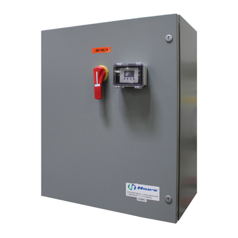
The standard TWBS.EW.H is sized to heat enough water for one eyewash at a time. This Water
Heating System should be installed in close proximity to the eyewash. It should be clearly
identified, with easy access and free from obstructions. Supply lines connected to this unit must
be heat traced if subject to freezing temperatures. If the piping network from the heater (located
indoors) to the fixture passes through a cold area, piping should be heat-traced with self-
regulating heat tape. Any heat-traced piping should be protected with scald protection bleed
valves. Additionally, should the TWBS.EW.H be mounted at a distance greater than 50 feet from
the eyewash, these runs should be evaluated by a plumbing engineer. Complicated chains of
eyewashes, long piping runs, and recirculating loops should all be evaluated by a qualified
engineer.
NOTE: If for any reason the heater is starved of water while power remains on, the unit may be
damaged. Also, the heating elements only turn on under flow, so any water within the heater
will be subject to atmospheric conditions most of the time. Therefore, the heater should never
be stationed outdoors or in a freezing environment.
GENERAL
To obtain optimum performance and energy savings from your Haws heater, the unit should be
located as near as possible to the point of use. The unit must only be installed in a vertical
position with the inlet and outlet at the bottom.
The power is activated by individual electronic flow switches located in each of the three heating
modules. These modules will be damaged by excessive heat; do not solder any pipes that are
in contact with the heater.
Also ensure pipes are clear of installation debris before fitting the heater, otherwise the switches
could jam in the “on” position. The unit must be connected to its own individual electrical flow
circuit protected by a suitably rated three pole breaker. The maximum voltage which can be
applied across any heating module is 480 volts.


