Haysys PIU User manual

© HAYSYS Limited 2018 www.haysys.co.uk TD00040
HAYSYS LIMITED
PHASE IDENTIFICATION UNIT
PIU USER MANUAL

Page 2 of 31
PHASE IDENTIFICATION UNIT
HAYSYS LIMITED
TABLE OF CONTENTS
1SAFETY AND WARNINGS ........................................................................................... 3
1.1 E-Field Probe ...............................................................................................................5
1.2 Lithium Ion Battery......................................................................................................5
2PIU SHIPPING ........................................................................................................... 6
2.1 Package Contents ........................................................................................................6
2.2 PIU Shipping Mode ......................................................................................................6
3LEVELS OF DOCUMENTATION....................................................................................7
3.1 1st Level - Attached to the PIU Unit..............................................................................7
3.2 2nd Level – A5 Size Quick Reference............................................................................. 7
3.3 3rd Level – This Manual ................................................................................................8
3.4 On-line Training Videos ...............................................................................................8
4BUTTONS AND INDICATIONS.....................................................................................9
5THEORY OF OPERATION.......................................................................................... 11
5.1 General Operation.....................................................................................................11
5.2 Location of the Remote Reference Unit ....................................................................12
6USING THE PIU........................................................................................................ 13
6.1 Checking the battery charge state .............................................................................13
6.2 Turning the Unit On ...................................................................................................13
6.3 Turning the Unit Off...................................................................................................13
6.4 Setting the Reference Phase......................................................................................13
6.5 Rotating the Reference Phase ...................................................................................13
6.6 Setting the PIU to operate with Anti-Clockwise Phase Rotation................................14
6.7 Measured Phase Indications......................................................................................14
6.8 Operating Modes.......................................................................................................14
6.8.1 User Mode ........................................................................................................15
6.8.2 Engineering Mode.............................................................................................15
6.8.3 Status Mode...................................................................................................... 15
6.9 Error Indications ........................................................................................................15
6.9.1 Low Battery Charge...........................................................................................16
6.9.2 Lost Communications........................................................................................16
6.9.3 No GPS Signal ....................................................................................................16
6.10 Reset Buttons ........................................................................................................16
7CONNECTIVITY........................................................................................................ 17

Page 3 of 31
HAYSYS LIMITED
PHASE IDENTIFICATION UNIT
8THE PIU UTILITY APPLICATION................................................................................. 18
8.1 Configuring the PIU and SIM Card Connection ..........................................................18
8.2 Setting up the Remote Reference Unit ......................................................................20
8.3 Closing the PIU Utility Application .............................................................................22
9REMOTE REFERENCE UNIT....................................................................................... 23
10 UPLOADING PHASE MEASUREMENT DATA ......................................................... 25
11 CHARGING ......................................................................................................... 26
11.1 Charging Voltage and Details ................................................................................26
12 MECHANICAL DETAILS........................................................................................ 27
12.1 Environmental Protection .....................................................................................27
12.2 Removing the Connector Cover.............................................................................27
12.3 Insertion and Removal of SIM Card.......................................................................28
13 AVAILABLE OPTIONS .......................................................................................... 30
13.1 Carry Case .............................................................................................................30
13.2 In-Car Charger .......................................................................................................30
13.3 E-Field Probes........................................................................................................30
14 WARRANTY AND SUPPORT................................................................................. 31
LIST OF TABLES
Table 1 - Table of Buttons and Indications ...............................................................................9
LIST OF FIGURES
Figure 1 - Operators Guide attached to the underside of the PIU ............................................7
Figure 2 - PIU Quick Reference .................................................................................................7
Figure 3 - Front Panel Buttons ................................................................................................10
Figure 4 - Theory of Operation – PIU Context.........................................................................11
Figure 5 - Phase Indication Vectors ........................................................................................14
Figure 6 - PIU Reset Button ....................................................................................................16
Figure 7 – Charging and USB Connector .................................................................................17
Figure 8 - Device Manager Screen .......................................................................................... 18
Figure 9 - PIU connected ........................................................................................................19
Figure 10 - IP Address details entered and saved...................................................................19
Figure 11 - PIU APN Details.....................................................................................................20
Figure 12 - Reference Unit connected ....................................................................................20
Figure 13 - Bridge Server details.............................................................................................21
Figure 14 - Bridge Server Active..............................................................................................21
Figure 15 - Bridge Server ........................................................................................................22

Page 4 of 31
PHASE IDENTIFICATION UNIT
HAYSYS LIMITED
Figure 16 - Closing the PIU Utility ...........................................................................................22
Figure 17 - Closing the PIU Utility warning .............................................................................22
Figure 18 – Remote Reference Unit Configuration.................................................................23
Figure 19 - Charging via the USB.............................................................................................26
Figure 20 - PIU and Reference Dimensions.............................................................................27
Figure 21 - Connector Cover Release......................................................................................28
Figure 22 - Pinching the Connector cover release catches .....................................................28
Figure 23 - SIM Card Holder – PIU connection cover removed............................................... 29

Page 5 of 31
HAYSYS LIMITED
PHASE IDENTIFICATION UNIT
1 SAFETY AND WARNINGS
1.1 E-Field Probe
Care must be taken when using the PIU with E-Field Probe, to ensure that the Probe does not
come into dangerous contact unintentionally with people and equipment. The PIU includes an
internal E-Field probe and as such, the external probe is only required where the signal level is
too low to determine the phase of the radiated E-Field.
1.2 Lithium Ion Battery
Please observe the following warnings, as the PIU battery contains lithium that may cause
heating rupture or ignition if not used correctly.
THE PIU UNIT IS NON-USER SERVICABLE AND NO ATTEMPT SHOULD BE MADE TO CHANGE THE
LITHIUM ION BATTERY.
The PIU contains a Lithium Ion Battery and must not be packaged or transported if damaged.
The charging time from a discharged state to a fully charged state is 3 hours with the battery
supplying sufficient power to the PIU to enable operation for a minimum of 8 hours from a fully
charged state.

Page 6 of 31
PHASE IDENTIFICATION UNIT
HAYSYS LIMITED
2 PIU SHIPPING
2.1 Package Contents
The supplied PIU package includes the following items:
a. PIU unit Part Number: H00310
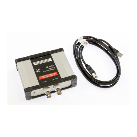
b. Micro USB lead, 1m, Black Part Number: MC000948
c. Mains Charger, 12V D.C. Part Number: VEL24US120-UK-JA
d. External E-Field Probe Part Number: 148-152YAGI
2.2 PIU Shipping Mode
Whilst in this mode, the PIU will be unresponsive to any button presses as the battery is
disconnected for storage and shipping. When the PIU is connected to either the mains charger
or to a charging source via the USB connector, the PIU will automatically come out of the
Shipping Mode and will be ready for operation and testing. The PIU will re-enter the Shipping
Mode each time the PIU internal battery becomes disconnected.

Page 7 of 31
HAYSYS LIMITED
PHASE IDENTIFICATION UNIT
3 LEVELS OF DOCUMENTATION
3.1 1st Level - Attached to the PIU Unit
Figure 1 below, shows the basic operation details of the PIU. A line under the ‘F’ character only
indicates a short press of that button, while a line underneath the ‘F’ character and the following
character indicates a press of three seconds or more is required.
Figure 1 - Operators Guide attached to the underside of the PIU
3.2 2nd Level – A5 Size Quick Reference
An A5 size Quick Reference is also available, that provides an intermediate level of information
between the PIU label and the User Manual.
Figure 2 - PIU Quick Reference

Page 8 of 31
PHASE IDENTIFICATION UNIT
HAYSYS LIMITED
The Quick Reference is a double sided A5 sized document that can also be downloaded from our
website, www.haysys.co.uk.
3.3 3rd Level – This Manual
The final level of documentation is this manual which is also available as a pdf download from
our website – www.haysys.co.uk.
3.4 On-line Training Videos
HAYSYS is pleased to provide short videos, showing how to operate the PIU. These videos can be
downloaded free from http://support.haysys.co.uk/PIU/PIUHome.aspx (registration required).

Page 9 of 31
HAYSYS LIMITED
PHASE IDENTIFICATION UNIT
4 BUTTONS AND INDICATIONS
The PIU unit has been designed so that user interaction is kept to a minimum whilst providing
clear phase indication. However, to further aid the user, additional functionality and displays
have been provided but this is deliberately kept to a minimum.
Table 1 - Table of Buttons and Indications
LABEL FUNCTIONS
F1
a) Turn on. Press for more than 3 seconds and release.
b) When pressed for more than 3 seconds, with F4 held
down, the PIU will enter ‘Configuration Mode’.
c) Upload the measured phase to the reference. Press for
more than 3 seconds and release.
d) Cancel phase reference. Hold for more than three
seconds and then simultaneously short press on F2.
e) Turn off. Press with F2 for more than three seconds.
F2
a) Turn off when pressed with F1 for more than 3 seconds.
b) Set Phase reference.Short press.
c) Cycle the phase reference. Hold for more than three
seconds and then simultaneously short press on F3.
F3
a) Cycle Status. Short Press. (e.g. Battery level displayed on
D2).
b) Cycle the reference phase.
Short press simultaneous
with a long press on F2.
c) Press for more than 3 seconds when powered down, will
cause the battery level to display on D2.
F4
a) Retry Communications. Short press to re-establish
mobile communications.
b) Long press to leave configuration mode and power up
fully.
D1
Gradient display showing the Electric Field strength being
detected
D2 Status Gradient Display – e.g. Battery Status
Amber LEDs F1-
F4
Button press confirmation. F1 and/or F2 flashing indicates the
unit is going through its power-up or power-down cycle.
D1 Green LED The PIU is in the Anti-Clockwise Phase Rotation Mode.
D2 Green LED Indicates when the PIU is connected to the Remote Reference
Network/PC.

Page 10 of 31
PHASE IDENTIFICATION UNIT
HAYSYS LIMITED
Figure 3 - Front Panel Buttons
F1 – F4 Amber LEDs
D1 and D2 Green LEDs
Phase Indication
Vectors
F1 – F4 Buttons

Page 11 of 31
HAYSYS LIMITED
PHASE IDENTIFICATION UNIT
5 THEORY OF OPERATION
5.1 General Operation
The purpose of the PIU is to identify the connected electrical phase of a residential or
commercial property without entering the property or connecting equipment to the property.
Equally, there is no requirement to install any equipment within the local substation.
Figure 4 below, shows the context in which the PIU is used and the various data connectivity the
unit uses to achieve this identification.
PHASE IDENTIFICATION UNIT REMOTE REFERENCE UNIT
RESIDENTIAL OR
COMMERCIAL
PROPERTY
RADIATED
ELECTRIC AND
MAGNETIC FIELDS
MAINS SUPPLY
SATELLITE
COMMUNICATIONS SATELLITE
COMMUNICATIONS
MOBILE COMMUNICATIONS
Figure 4 - Theory of Operation – PIU Context
The PIU is able to measure the instantaneous phase of the electrical field being radiated by any
property. The original source of this radiation does not have to be the properties internal
electricity meter, but can be any live cable, including the electrical connection to internal lights,
sockets and any external lights.
The PIU is then time synchronised with a remote reference unit that is also measuring the
instantaneous phase of the mains supply connected to it. The remote reference unit then
communicates this phase measurement (along with other data, such as GPS time), to the PIU
using the integral mobile communications link.
The time synchronisation between the PIU and the Remoter Reference Unit is achieved through
the 1-second timing provided by the GPS Satellites. This is a very accurate timing reference
source.
With the two units in synchronisation and communicating, the PIU compares both sets of data
and is able to determine and display the properties connected phase, within 10 seconds.

Page 12 of 31
PHASE IDENTIFICATION UNIT
HAYSYS LIMITED
The PIU measures the instantaneous phase that varies with the changes in the mains frequency.
However, since the same frequency variation is also seen by the Remote Reference Unit, the
variation is cancelled out.
NOTE: For this reason, an additional Remote Reference Unit is required where the frequency of
the mains supply to the Remote Reference Unit, is not phase locked to frequency of the mains
supply at the place where the PIU is making measurements (e.g. Mainland European based PIU
locations cannot use the UK based Remote Reference Unit in Cardiff. They must use a Remote
Reference Unit installed within Mainland Europe).
The measured phase is required to be within ±30° of one of the three display vectors that are
separated by 120°, in order to display the vector on the unit.
The measured phase can be uploaded to the reference unit by pressing F1 for more than 3
seconds and releasing the button. An example of the data uploaded is shown below:
•L1,4,5,$GPRMC, 105412.00,5130.11239, N, 0307.14367, W, 347, 050
•L2,3,2,$GPRMC, 105412.00,5130.11239, N, 0307.14367, W, 097, 050
•L3,3,1,$GPRMC, 105412.00,5130.11239, N, 0307.14367, W, 214, 050
The format of the data may differ from that shown but will always have the detected phase (L1
or L2 or L3 as shown) L0 indicates unknown phase.
The remaining data shown in the examples include the accurate date/time field, followed by the
Latitude and Longitude GPS co-ordinates for the PIU at the time of the data upload (51°
30.11239”N 03° 07.14367”W – HAYSYS, Cardiff). It also includes the instantaneous phase and the
reference phase (050 = L2 in this case).
5.2 Location of the Remote Reference Unit
Traditionally, other systems require a reference unit to be installed within the local substation.
This is not the case with the HAYSYS PIU. Only a single Remote Reference Unit is required for
the whole Distribution Network. The only need for an additional reference unit is when one
Distribution Network is not Phase Synchronised with the Distribution Network where the PIU is
being used (e.g. using the PIU in Europe and connecting to a Remote Reference Unit installed
within the UK). HAYSYS has a Remote Reference Unit installed at its offices in Cardiff. This is
sufficient to allow PIU users to operate the PIUs anywhere within the United Kingdom.
Of course, customers can also purchase their own Remote Reference Unit if they so wish, but
this is not necessary.
Should a phase change be present between two points across a single Distribution Network,
then the HAYSYS PIU allows the phase reference to be offset locally from the Remote Reference
Unit. The unit also accepts changes due to WYE-DELTA connections. The PIU operator can rotate
the phase reference stored within the PIU to correct for this phase change (see section 5.4 to
see how to do this).
It is recommended that prior to its use, the phase indicated by the PIU is confirmed to be correct
by measuring the phase of a known point (this could be within the substation or any other
property where the phase is known to be correct). If it is not, then the reference phase of the
PIU should be rotated until the PIU indicates the correct phase.

Page 13 of 31
HAYSYS LIMITED
PHASE IDENTIFICATION UNIT
6 USING THE PIU
6.1 Checking the battery charge state
Whilst the PIU is in its powered down state, a short press on the F3 button, will cause the unit to
display it s battery charge state on the D2 scale for several seconds, before returning to its off
state.
6.2 Turning the Unit On
Press F1 for three seconds or more and then release. The unit will then commence its power up
sequence that will be completed when all three phase vectors are illuminated completely. The
unit is then ready to use, assuming the PIU has both mobile and GPS connectivity.
NOTE: if the reference phase has been previously set then the unit will remember this and after
a short period following its power cycle, will turn off the phase vectors or display a single vector
if within the proximity of a detectable cable. After powering on the unit, if any of the bars are
blinking, then initialisation of either the GPS or mobile communications is not complete.
6.3 Turning the Unit Off
Press F1 and F2 together for more than three seconds and release. This will cause the unit to
start its power down sequence which will turn off all LED indications when completed. The unit
will actually be put into a low power sleep mode and will only completely turn off when the
battery charge state is below the minimum required. If this happens it may take up to 20
minutes to reacquire the GPS position.
6.4 Setting the Reference Phase
If the unit has had its reference phase cleared, either by the battery becoming discharged or
being cleared by the user, then all three phase vectors will be illuminated. The Reference Phase
must be set. In order to set the reference phase, the unit must be in communication with the
Remote Reference Unit and have a GPS lock.
Hold the PIU close to a single-phase powered item (e.g. substation fuse holder, lighting switch
etc.), where the phase of the powered item is known. The E-Field signal level (D1) should be
showing near to a maximum signal level. Wait for 20 seconds and then briefly press F2. The unit
should respond by leaving only the vertical phase vector illuminated. If the unit does not turn
off the other phase vectors then this indicates that the unit has been unable to identify a single-
phase field free of interference from other phases. In this case, the user should repeat the
procedure or set the phase at a different location.
NOTE: If the known phase corresponds to the phase vector being displayed (e.g. Red phase or
L1), then the reference phase will not need to be rotated (as described in the section 6.5).
6.5 Rotating the Reference Phase
With the reference phase set but the unit is displaying the incorrect phase vector, Press and hold
F2 for three seconds or more, then press F3 briefly and release, then release F2. The unit will
respond by rotating the phase vector clockwise (or anti-clockwise when in anti-clockwise phase
rotation mode), to the next phase vector. Repeating this procedure will rotate to the next phase
vector and so on.

Page 14 of 31
PHASE IDENTIFICATION UNIT
HAYSYS LIMITED
6.6 Setting the PIU to operate with Anti-Clockwise Phase Rotation
It may be required that the PIU is to be operated in an area, where the phase rotation is anti-
clockwise instead of clockwise. The PIU has the facility to be able to be set for this operation by
pressing and holding F3 whilst pressing F1 to power the PIU. Whilst in this mode of operation,
the green D1 LED will be permanently lit, indicating the anti-clockwise phase rotation operation.
Also, whilst in this mode, incrementing the phase referencing (Long F2 followed by a short F3),
will cause the reference to rotate in an anti-clockwise direction.
6.7 Measured Phase Indications
In this section, it is assumed that the reference phase of the PIU being used has been set (see
sections 6.4 and 6.5 for further details).
Place the unit as close as possible to the property or equipment where the single phase is being
determined. If the unit can identify the phase of the measured E-Field, then it will illuminate the
corresponding phase vector. If the E-Field is weak, the sensitivity of the PIU can be improved by
fitting the external E-Field probe (supplied).
For the user to be confident that the displayed vector is the correct phase, the displayed vector
must remain illuminated for a minimum of 10 seconds.
The single phase of the property or equipment supply has been identified and displayed.
Figure 5 - Phase Indication Vectors
6.8 Operating Modes
In order to provide additional information to the user, the PIU offers three Operating Modes,
User Mode, Engineering Mode and Status Mode.
The PIU will always power up into the User Mode. The mode can then be cycled by a short press
and release of the F3 button.
The different modes of operation do not change the PIU functionality but provide different
levels of information through its varying indications.
Phase Identified
E-Field Strength

Page 15 of 31
HAYSYS LIMITED
PHASE IDENTIFICATION UNIT
6.8.1 User Mode
This is the normal operating mode that is used when identifying the phase of properties or
equipments. It provides all the required indications.
When in this mode, the displays used are as described in previous sections, but with the addition
of two further indications.
a. Loss of Communications with the Reference Unit -indicated by the inner most LED
of each of the phase vectors switching on and off in turn, giving a rotation effect.
b. Loss of GPS Information – The two outer LEDs of each of the three phase vectors
flashing on and off at the same time.
If the PIU is indicating either of the above conditions, then the displayed phase is not verified.
Also, the reference phase cannot be set if either or both of the above conditions are being
displayed. However, brief loss of GPS signal e.g. when shaded by buildings will not nullify the
displayed phase accuracy. However, the location (if uploaded) will not be known.
6.8.2 Engineering Mode
When in User mode a short press and release of the F3 button will change the operation mode
into the Engineering Mode.
If the PIU is operating normally and receiving all of the reference data and GPS information, then
the unit displays operate in the same way as when the unit is in User Mode. However, should
the unit not be working correctly, then this mode provides the user with further information:
a. Outer portion of the Vector Display flashing – indicates that the reference phase has
not been set. This is the same as all three vectors displaying in User Mode. The PIU is
actually displaying the instantaneous phase of the E-Field probe. F1 will upload this
information and may be used to recover the detected phase.
b. The inner most LED of each of the phase vectors switching on and off in turn, giving a
rotation effect – Loss of communications with the Reference Unit. This could be loss
of mobile phone connectivity or a problem with the reference unit. This indication is
also present in User Mode.
6.8.3 Status Mode
When in Engineering mode a short press and release of the F3 button will change the operation
mode into the Status Mode.
In this mode, the PIU will operate the same as when in User Mode but will now provide
additional status information:
a. Gradient Display D2 will now display the units Battery Charge level.
A further short press and release of the F3 button will change the operation mode back to the
User Mode.
6.9 Error Indications
The PIU requires a minimum level of data and battery charge in order to operate.

Page 16 of 31
PHASE IDENTIFICATION UNIT
HAYSYS LIMITED
6.9.1 Low Battery Charge
The unit’s battery charge level is indicated by D2 when the unit is in Status Mode (see section
6.8.3 for further details). If the unit is not sufficiently charged, then it will not successfully
complete its power up procedure when initially switched on.
The unit should be placed on charge with either the mains D.C. 12V power supply (supplied) or
by using a high current (1A or greater) USB charger (see section 7 for further details).
6.9.2 Lost Communications
If the unit has lost communications with the reference unit then a phase cannot be determined.
Lost communications with the Remote Reference Unit is indicated by the inner portion of the
three phase vectors lighting in turn and showing a rotating action.
6.9.3 No GPS Signal
If the unit has lost communications with the GPS Satellites, then the 1 second reference timing
pulse will not be available. In this situation, the unit will use its internal 1 second reference and
continue to provide a reference indication.
6.10 Reset Buttons
The PIU also has a single reset button as shown in Figure 6 below:
Figure 6 - PIU Reset Button
The reset is operated by pressing and holding down on the top surface of the button for 14
seconds.
NOTE: If the Main Processor Reset is operated then the PIU reference will be deleted and will
have to be set again before the PIU can be used to identify a phase.
Main Processor Reset

Page 17 of 31
HAYSYS LIMITED
PHASE IDENTIFICATION UNIT
7 CONNECTIVITY
The PIU has a full speed USB 2.0 Interface located under the connection cover as shown in Figure
7 below.
Figure 7 – Charging and USB Connector
The PIU can be charged from either the Charging Power Socket or the USB Connector.
USB Connector
Charging Power Socket
Charging Indicator

Page 18 of 31
PHASE IDENTIFICATION UNIT
HAYSYS LIMITED
8 THE PIU UTILITY APPLICATION
8.1 Configuring the PIU and SIM Card Connection
In order to configure a PIU, the unit must be placed into its configuration mode, with an active
SIM card installed (see section 12.3 for details). With the unit powered off, press and hold F4
and then press F1 for 3 seconds or more, then release F1 and then F4. The unit should power up
into its configuration mode as indicated by F4 staying on. The unit may now be plugged into the
host PC using the supplied USB cable.
On checking the Device Manager of the Host PC that the PIU is connected to, the PIU Device will
be listed under the Ports (COM & LPT) section along with its allocated COM port number –
COM3 in the example shown in Figure 8 below.
Figure 8 - Device Manager Screen
The HAYSYS PIU application can now be started and the ‘Scan for devices’ button pressed. The
application will respond by automatically identifying if the connected unit is a PIU or a Remote
Reference Unit (RRU).

Page 19 of 31
HAYSYS LIMITED
PHASE IDENTIFICATION UNIT
Figure 9 - PIU connected
Next, select the IP Address tab and enter the external static IP address and port of the Remote
Reference Unit (RRU) to be used with the PIU. Press the ‘Save’ button and ensure that the
button changes to the green colour as shown in Figure 10 below.
Figure 10 - IP Address details entered and saved
Next set the Access Point Name (APN) Details by selecting the ‘APN Details tab’. Here, enter the
APN details for the mobile carrier’s SIM Card that will be used in the PIU.

Page 20 of 31
PHASE IDENTIFICATION UNIT
HAYSYS LIMITED
Figure 11 - PIU APN Details
Press the ‘Save’ button and ensure that the button changes to the green colour.
The PIU configuration is now complete and the unit can be fully powered up by pressing the F4
button for 3 seconds, or more, to place the unit into its operational state.
8.2 Setting up the Remote Reference Unit
If a Remote Reference Unit is to be used, then this section details how the HAYSYS PIU Utility is
used to perform the data ‘bridge’ between the IP Address and the USB port on the RRU.
NOTE: The PIU Utility must be running on the Host PC at all times when the PIU units are being
used in the field.
As with the PIU configuration procedure, connect the RRU to the host PC via the supplied USB
cable. Start the PIU utility application on the host PC and press the ‘Scan for device’ button. The
utility will automatically identify the connected RRU as a reference unit as shown in Figure 12
below.
Figure 12 - Reference Unit connected
Next, set the server address by selecting the ‘Server’ tab and entering the IP address of the host
PC. The IP address can be ‘discovered’ by clicking on the ‘Discover’ button. This will
automatically enter the IP address of the host PC or present a ‘drop-down’ list, if multiple IP
Addresses are discovered. Next enter the port number to be used, as shown in Figure 13 below.
Table of contents
