Hayward DuraNiche User manual
1. All DuraNiche™ underwater lighting fixture housings are Underwriters Laboratories (UL) Listed under File E 39338- Category
WBDT. These niches are New York City (NYC) Bureau of Electrical Control approved for use with low voltage (12 volt) lighting fix-
tures. U.L. Listed for fresh water and complies with 1999 National Electrical Code [NEC].
2. DuraNiche™ model SP0600U and SP0607 underwater fixture housings are UL Listed only for use with Hayward Submersible
Light Fixture Series SP 0540, SP 0570, SP 0580 and SP 0580S. Model SP 0601 Underwater Light Fixture Housing (Niche) is UL
Listed for use with Hayward Submersible Light Fixture Series SP 0590.
3. All DuraNiche™ underwater lighting fixture housings must be installed in compliance with Article 680 of the National Electrical
Code (NEC) or other applicable electrical codes and with any applicable building codes. Article 680 requires that light fixtures be
installed with the top of the fixture lens at least 18 inches below the normal water level of the pool or spa.
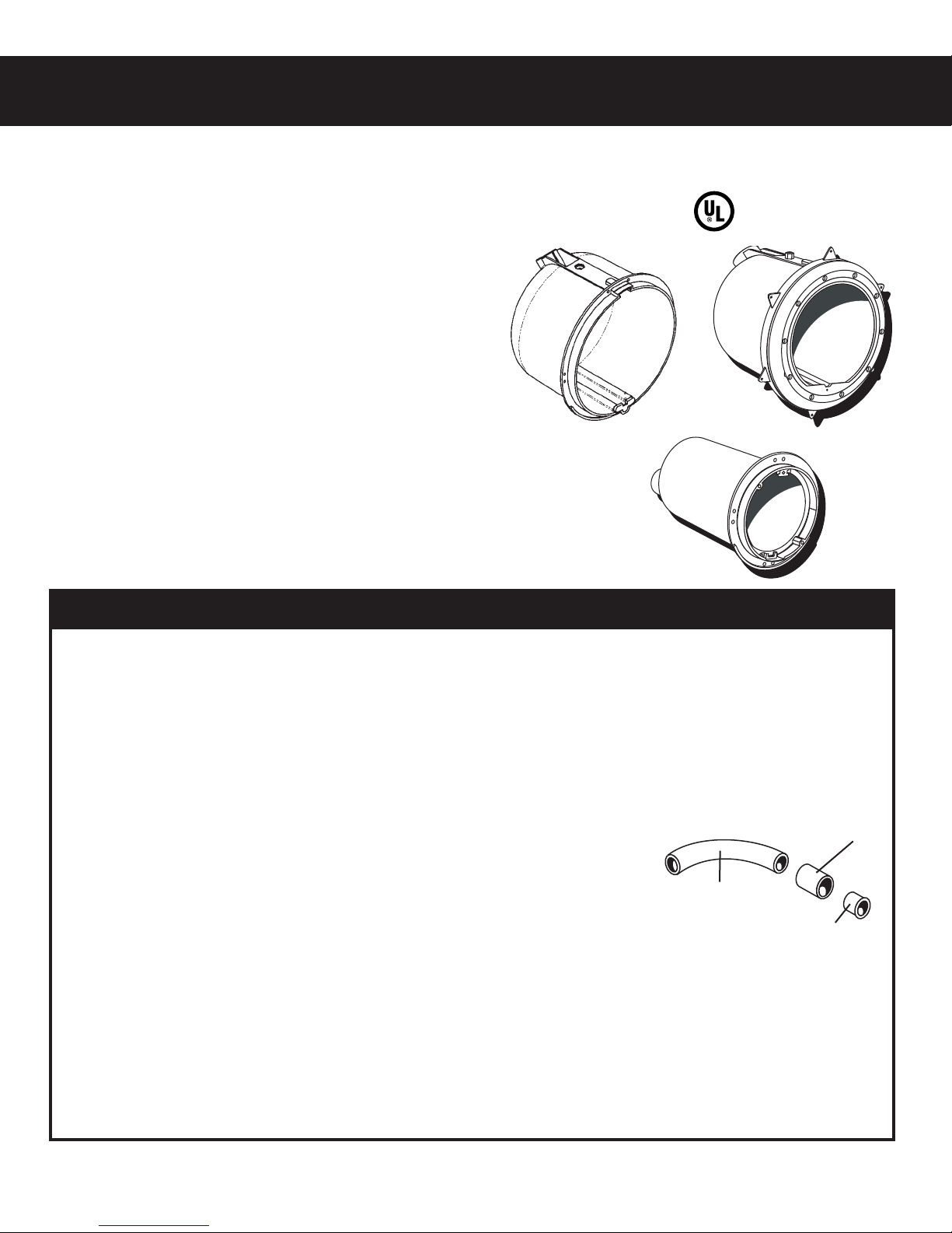
4. All DuraNiche™ underwater lighting fixture housings are provided with three (3) UL Listed
Conduit Fittings. A 1" trade size -45° sweep elbow is provided for the purpose of directing
the conduit pipe towards the SP 0680/ SP 0681 Listed Junction Box location. A 1" conduit
pipe coupling is provided for the purpose of connecting the conduit pipe to the 45° sweep
elbow. A 1" - 3/4" reducer bushing is provided to permit the use (in conjunction with the 1"
coupling) of 3/4" conduit pipe. These conduit fittings must be cemented to the fixture hous-
ing (niche), field supplied conduit pipe and to other conduit fittings using approved PVC
primer and cement.
5. All DuraNiche™ underwater lighting fixture housings are provided with a combination bonding/grounding connector. The outside
connection is the bonding connector as required by Article 680-22 of the NEC. The NEC requires that the bonding wire be AWG 8
or larger. Local codes may require a continuous loop and may require that the bonding point on the fixture housing (niche) be
encapsulated. The inside connection is the grounding connector as required by Article 680-20 (b) of the NEC. The NEC requires
that where a nonmetallic conduit is used, an AWG 8 insulated copper conductor be installed in this conduit. This conductor is to be
connected to the niche grounding connector. The connector and wire termination must be encapsulated in 3M Inc. Scotch Cast
Wet Niche Potting Compound No. 2135 (UL File E130394) or equivalent to protect such connection from the possible deteriorat-
ing effect of pool water.
6. All DuraNiche™ niches are equipped with Internally-threaded connection for pressure testing of conduit line before installing light.
HAYWARD®
DuraNiche™SERIES
UNDERWATER LIGHTING FIXTURE HOUSINGS
MODEL NO. SP0600U-FOR CONCRETE POOLS
MODEL NO. SP0601U-FOR CONCRETE POOL/SPA
MODEL NO. SP0607U- FOR VINYL/FIBERGLASS POOLS
Approved for use by NYC
Department of Buildings
INSTALLATION INSTRUCTIONS
SAVE THESE INSTRUCTIONS
Unlike metallic niches, DuraNiche™ niches are
injection-molded of PVC for superior performance,
non-corrosive durability and plumbing versatility -
plus the lowest installed cost.
The ability to accept PVC over expensive metal
conduit enables DuraNiche™ to offer true bottom
line savings in materials, as well as time to install.
DuraNiche™ comes in three models for concrete/gunite pools,
vinyl/ fiberglass pools, or for concrete/gunite spas. When paired
with a Hayward AstroLite™ or AstroLite II™ light fixture, you have
the best quality and value in a lighting system available anywhere.
To facilitate installation, all DuraNiche™ fixture housings are
packed with U.L. listed conduit fittings (reducer, elbow, and cou-
pling.)
IS0600UA-03 Rev A
SP0600U
SP0601U
SP0607U
IMPORTANT INFORMATION REGARDING ALL MODELS
45° ELBOW
(SP0600M)
UL LISTED CONDUIT
FITTINGS
1” COUPLING
(SP0600N)
1” TO 3/4”
REDUCER
(SP0600P)

FEATURES COMMON TO SP0600U AND SP0601U- FOR CONCRETE POOLS
1. 3/4" set-back plaster flange with tie-off holes to secure to rebar and assure positive positioning during guniting.
2. Unique 90° ledge at the flange bottom prevents "slumping" during plastering.
3. Niche cover (see back page) included with each niche, protects the niche and mounting threads during guniting.
4. The SP0601U small diameter niche has extra space for easy coiling and storage of the relamping cord.
Models SP0600U (Pool) and SP0601U (Spa) Underwater Lighting Fixture Housings are intended for installation in
pools or spas with floors and walls formed of gunite or concrete (shotcrete) with a concrete reinforcing bar (rebar)
frame. Gunite is a mixture of Portland Cement and sand while shotcrete is a high strength (4000 psi) concrete utiliz-
ing Portland Cement and small size aggregate.
The outside shape of the pool or spa is formed from SteelTek or other suitable material.
In some cases, the excavated dirt wall will serve as the outside form. The inside wall of
the pool or spa is formed from rebar that is bent to the desired shape (See Illustration A ).
The distance between the outer and inner wall is called the beam and is typically 8 to 12
inches. Rebar steel should be set at 10” for a 12” beam and 8” for a 10” beam. The dis-
tance between the niche flange and the outer wall should be the beam dimension. At all
points where the rebar crosses, tie wire is used to connect the rebar securely.
1. Position the Model SP 0600U (Pool) or SP 0601 U (Spa) between adjacent rebars
such that the niche is held on four sides by sections of rebar. At the time the niches
are installed it may be necessary to add sections of rebar or move existing sections to
one side or another in order to insure that the niche is held securely. See illustration
(B)
THE NEC REQUIRES THAT THE TOP OF THE LIGHT LENS BE AT LEAST 18 INCH-
ES BELOW THE WATER LEVEL. BE SURE TO POSITION NICHE SO THAT YOU
COMPLY WITH THIS REQUIREMENT. SOME INSTALLERS POSITION NICHE 24
INCHES BELOW ANTICIPATED WATER LEVEL TO AVOID ANY INSPECTION
AUTHORITY ISSUES WITH THIS REQUIREMENT.
2. Once the niche(s) has been securely positioned (wedged) in the rebar it must be
securely tied to the rebar with tie wire. Before tying niche in place make certain that
niche is (vertical) plumb, and square to the form and that top of niche (where retaining
screw is located) is at highest point at the 12 O’Clock posiiton. The flanges of Niche
Models SP0600U and SP0601U are provided with .187" diameter holes through which
tie wire may be routed to facilitate securing the niche to the rebar. Tie wire should also
be wrapped tightly around the outer circumference of the niche and then tied to the
rebar. Once the niche is tied in place confirm that it is still plumb and that the distance
from the outer wall to the niche flange is the correct beam dimension
NOTE: The rebar will be approximately 2 inches from where the inside finished surface of
the pool will be. You must be sure to leave approximately 2” between the DuraNiche™
flange and the rebar (see illustration C)
3. After attaching the niche to the rebar of the pool wall and cementing conduit and conduit
fittings in place and connecting the #8 AWG bonding wire to the bonding connector as
described, install the provided DuraNiche™ Cover. The niche cover must be installed in order to prevent gunite or
concrete from entering the inside of the niche during the pouring/shooting process. Cover should be left in place until
the light is installed in the niche. (see illustration C)
4. The outside bonding connection must be inspected before the concrete/gunite, pouring/shooting operation. Follow
applicable codes. It is also necessary to keep concrete or gunite from hardening on the outer edge and flange of the
niche during pouring/shooting.
5. Once the concrete/gunite has completely dried, the niche is ready to be "plastered". Plaster is typically a mixture of
white Portland Cement and marble dust along with some pigment chosen to give the pool water the desired color.
The "plaster" is applied about 1" thick in the area surrounding the niche. The distance between the front edge and
the flange of the niche is filled with plaster.
18” TO
24” MINI-
MUM
2”
NICHE
COVER
8” TO 12”
A
B
C
2
INSTALLATION INSTRUCTIONS FOR SP0600U AND SP0601U
FEATURES EXCLUSIVE TO SP0607U- FOR VINYL/FIBERGLASS POOLS:
1.Attractive, injection-molded Duralon™ face rim assembly for corrosion-free performance.
2.Fits all standard punch designs, no tooling modifications are required.
3.Incorporates the dependability of Hayward's proven wall panel sealing method.
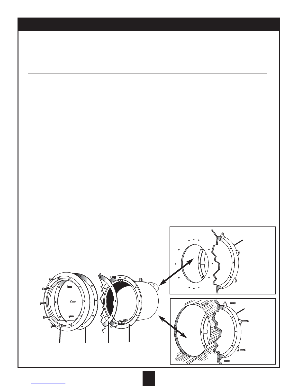
A. FOR VINYL LINED METAL WALL, FIBERGLASS PANEL OR FIBERGLASS POOLS
1. If not pre-punched by factory, drill and cut out wall panel sections as per dimensions below:
METAL OR FIBERGLASS PANEL CUT-OUT
CIRCULAR PANEL CUTOUT - 10 ¾" MAX. 10 5/8 MIN.
DRILL OR PUNCH - TEN (10) 5/16" HOLES ON 11 ½" B.C., SPACED 36°
DRILL OR PUNCH - TWO (2) ¼" HOLES ON 11 ½" B.C. SPACED 180°
2. Insert shell through panel section from interior of pool, securing Grounding Bracket at TOP (12 O'clock). For fiberglass
pools (without liner): Caulk rear side of shell flange with silicone or other suitable sealing compound prior to inserting shell
through pool wall.
3. Align the securing screw holes (at top and bottom) of the shell with those of the wall panel and insert the two pan head
securing screws through shell and panel. This step may be eliminated for fiberglass pools (without liner).
4. Align the holes of the backup rim with those on the exterior side of the wall panel and fasten the shell and backup rim to the
wall panel with the two No. 13 x 5/8" self-tapping pan head securing screws. For fiberglass pools (without liner): Caulk
front surface of backup rim prior to installing.
5. Align holes in gasket with holes in shell and affix to shell with small quantity of adhesive. Cement to hold gasket in place.
(Two large holes in gasket will fit over the pan heads of the securing screws.)
6. If vinyl lined pool, install liner before proceeding with Step 7.
7. Align second gasket (not required for fiberglass pools without liner) and face plate and fasten tightly to shell assembly with
ten (10) No. 13 x 1 ¼" flat-head self-tapping screws provided. Use a properly sized Phillips screwdriver to tighten these
heavy-duty screws. (Note: Make sure that the two countersinks on the back of faceplate line up with the heads of the two
securing screws.) If vinyl liner pool, pierce liner through faceplate holes one at a time prior to inserting screws. Secure
DuraNiche™ to pool with screws following this sequence:
a. FACEPLATE b. GASKET c. VINYL LINER (OPTIONAL)
d. GASKET e. DuraNiche™ f. POOL PANEL g. BACKUP RING
8. Be sure to follow pool manufacturer's instructions. If vinyl lined pool, cut out liner along inside edges of faceplate.
B. FOR WOOD OR FIBER PANEL VINYL LINER POOLS
1. Cut out wall panel to 12 3/8" maximum, 12 1/8" minimum O.D. (Approximately 1/8 " larger than O.D. of backup ring).
2. Insert backup ring through circular hole, from rear of panel, and fasten to rear of panel with (6) brass wood screws of prop-
er length (not furnished).
3. Insert shell through panel from interior of pool, securing
Grounding Bracket at TOP (12 o'clock).
4. Align the two securing screw holes at top and bottom of the shell with
those of the backup ring with two (2) No. 13 x 5/8" self-tapping pan
head securing screws.
REFER TO STEPS 5 THROUGH 8 AS ABOVE.
INSTALLATION INSTRUCTIONS FOR SP0607U
(10) #13 1 1/4” SCREWS
3
abd
g
g
c
e
f
f
(6) BRASS SCREWS
(NOT FURNISHED)
(2) #13 5/8” SCREWS
FOR VINYL
LINED METAL
WALL, FIBER-
GLASS
PANEL OR
FIBERGLASS
POOLS
FOR WOOD
OR FIBER
PANEL
VINYL
LINER
POOLS
A
B
PRODUCT SPECIFICATIONS
Hayward Pool Products Worldwide Locations
Hayward Corporate
Headquarters
Hayward Pool Products, Inc.
900 Fairmount Avenue
Elizabeth, NJ 07207, USA
Tel: 908 351 5400
Fax: 908 351 5675
Hayward Pool Products, Inc.
2875 Pomona Boulevard
Pomona, CA 91768, USA
Tel: 909 594 1600
Fax: 909 598 6905
Hayward Pool Products
Canada, Inc.
2880 Plymouth Drive
Oakville, Ontario
CANADA, L6H 5R4
TEL: 905 829 2880
FAX: 905 829 3636
Hayward Pool Products Europe:
Parc Industriel de la Plaine de L‘Ain
Allee Des Chenses
01150 Saint Vulbas
FRANCE
TEL: 33 4 74 46 24 70
FAX: 33 4 74 46 24 87
Hayward Iberica S.A.
Carretera Nacional III, KM 333, 7
Nave 2
E-46930 Quart De Poblet,
Valencia, SPAIN
TEL: 34 6 152 3454
FAX: 34 6 152 3357
Hayward/IMG
International Marketing Group
801 Corporate Center Drive,
Suite 110
Pomona, CA 91768, USA
Tel: 909 620 4041
Fax: 909 620 1249
For further information or consumer technical support, please call (East Coast) 908-351-5400,
(West Coast) 909-594-1600 or visit our web site at www.haywardnet.com
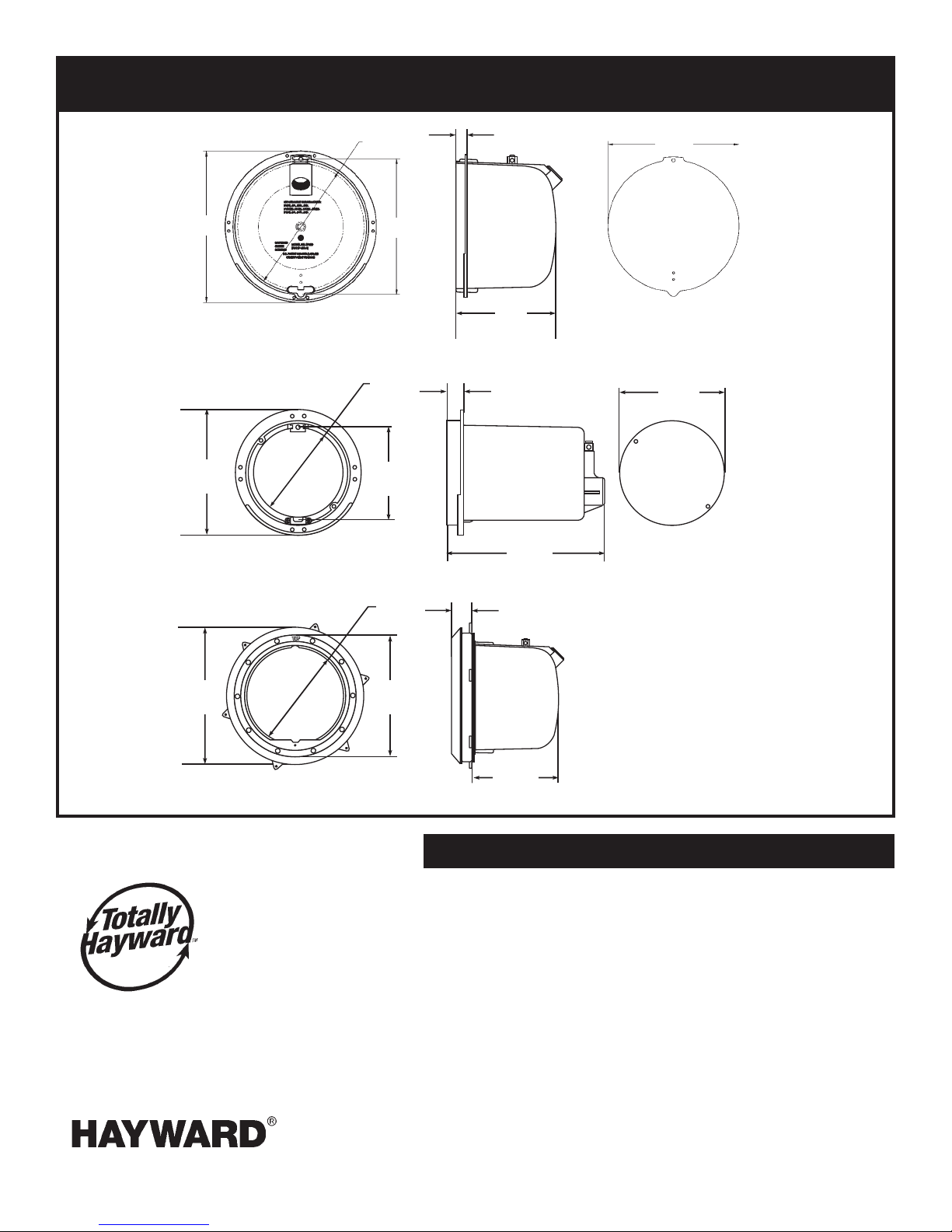
12.21”
6.50” 4.80”
4.63”
10.00”
12.19”
Dimensions varies
with wall thickness
8.156”
.850”
8.150”
6.50”
.850”
7.9”
DuraNiche™
SP0600U
DuraNiche™
SP0601U
Niche Cover-SP0600J
SPX0555Z2- Bolts (1)
Niche Cover-SP0601N
DuraNiche™
SP0607U
NOTE: These items are protected by the following patents:
#5.432.688. Other patents pending
SPX0507A1- Faceplate
SPX0507D- Backup Ring
SPX0506D- Gaskets (2)
SPX0555Z2- Bolts (1)
SPX0607Z1A- Screw Set 10 pcs. (1)
10.0”
10.0”
9.69”
11.13”
This manual suits for next models
4
Popular Camera Accessories manuals by other brands

Viltrox
Viltrox EF-NEX Mount instructions

Calumet
Calumet 7100 Series CK7114 operating instructions

Ropox
Ropox 4Single Series User manual and installation instructions

Cambo
Cambo Wide DS Digital Series Main operating instructions

Samsung
Samsung SHG-120 Specification sheet

Ryobi
Ryobi BPL-1820 Owner's operating manual


