Hansol Scalable All In One Series User manual

ELSR722-00004 / ELSR103-00001
Installation Manual
Scalable All In One
ELSR722-00004: Battery Tray (ELPT362-00004) x 2
ELSR103-00001: Battery Tray (ELPT362-00004) x 3
Use this product only at home.
Read the manual and all other available information.1.
2.
3.
4.
5.
6.
7.
8.
9.
10.
Attend Hansol installation training course/s. This course/s is recommended before the distributor
Provides an ESS.
Register as a Hansol installer.
Be compliant with CEC accreditation requirements for grid connect systems with batteries, which
currently requires o-grid installation accreditation.
Visit the installation site prior to quoting.
Check that the switchboard has room, or is suitable for, additional connection/s (e.g. external meter for
ESS 3.6 model).
Be aware of Dangerous Goods Class 9 regulations for transport, storage and handling of lithium
batteries.
Be aware of Building Code regulations for battery installations.
Read the manual again.
Ensure you have the latest version of the installation manual, which can be downloaded from your
distributor’s website.
The internet connection is required to use all functions of the ESS system.
If you have a problem, please contact the installer.
The Specications of the product may be modied without prior notice to improve product quality.
Do not operate with other components not approved by the ESS systems.
(Connecting other products in parallel to Hansol Technics’s products may result in abnormal operation.)
CAUTION
CAUTION
Australia (Eng.) 11/2016. Rev1.0

Table of Contents
i
Table of Contents
Table of Contents ............................................................................................................... i
Table of Tables.................................................................................................................. iv
Table of Figures ................................................................................................................. v
1. About this Manual ......................................................................................................... 1
1.1 Valid Range ....................................................................................................................................................1
1.2 Target Group..................................................................................................................................................1
1.3 Manual Storage ............................................................................................................................................1
1.4 Symbols Used................................................................................................................................................1
2. Safety.............................................................................................................................. 4
2.1 Intended Use .................................................................................................................................................4
2.2 Safety Precautions.......................................................................................................................................5
2.3 Product Overview........................................................................................................................................6
2.3.1 Basic Specications.......................................................................................................................7
2.3.2 Grounding the PV Inverter.........................................................................................................7
2.3.3 Fail-safe actions upon power failure.......................................................................................8
3. Package Removal and Inspection ................................................................................ 9
3.1 Package Removal and Tray Assembly...................................................................................................9
3.1.1 Removing the Enclosure Package ...........................................................................................9
3.1.2 Removing the Battery Tray Package .....................................................................................10
3.1.3 Checking Components on the Packing List.......................................................................11
3.1.4 Assembling the Battery Tray....................................................................................................12
3.2 Checking for damage in Delivery ........................................................................................................12
3.3 Identifying Hansol Scalable All in One ..............................................................................................13
4. Installation ................................................................................................................... 16
4.1 Selection of Installation Location ........................................................................................................16
4.1.1 Possible locations for installation ..........................................................................................17
4.1.2 Storing the ESS system..............................................................................................................17
4.1.3 Dimensions and Weight............................................................................................................18
4.1.4 Ambient Conditions and Temperatures..............................................................................18
4.1.5 Minimum Clearance ...................................................................................................................18
4.1.6 Position (Location Selection)...................................................................................................19
4.2 Mounting Instructions .............................................................................................................................20
5. Electrical Connections................................................................................................. 22
5.1 The Overview of Electrical Connection..............................................................................................23
5.2 Opening the Side Case Cover................................................................................................................28
5.3 The Overview of the Connection Area...............................................................................................29
5.4 Battery Installation ....................................................................................................................................30

Table of Contents
ii
5.4.1 7.2 kWh and 10.8 kWh Battery Installation.........................................................................30
5.4.2 Scalable (From 7.2 kWh to 10.8 kWh)...................................................................................31
5.5 Closing the Side Case Cover ..................................................................................................................34
5.6 A Method of Locking the Distribution Box (Board) .......................................................................36
5.6.1 AC Circuit Breaker and DC Isolator........................................................................................37
5.6.2 RCD (residual current device) Leakage Circuit Breaker..................................................37
5.7 Grid Switch Box Connection between Grid and System.............................................................38
5.8 A Connecting Method of DC and AC Line.........................................................................................46
5.8.1 Mounting........................................................................................................................................49
5.9 A connecting method of DRM connection .....................................................................................51
5.10 LAN Cable Connection between PC and System...........................................................................52
6. Communication Connection....................................................................................... 57
6.1 Internet Connection .................................................................................................................................57
6.1.1 Components..................................................................................................................................57
6.1.2 Connection Block Diagram ......................................................................................................57
6.1.3 Connection Method ...................................................................................................................57
7. Entering Initial Installation Information ................................................................... 58
7.1 Information Input Administrator..........................................................................................................58
7.2 System Information input stage...........................................................................................................58
7.3 Web Page Connection..............................................................................................................................59
7.3.1 Web Page Connection ...............................................................................................................59
7.3.2 Remote Monitoring ....................................................................................................................66
7.4 PC Direct Connection and Local Setting Value...............................................................................70
7.4.1 PC Direct Connection Flow ......................................................................................................70
7.4.2 Inserting Jumper Wire................................................................................................................70
7.4.3 LAN Cable Connection between PC and System.............................................................70
7.4.4 SIM (System Install Manager) Connection..........................................................................71
7.4.5 Operating test...............................................................................................................................73
7.4.6 Entering Setting Value ...............................................................................................................78
8. Operation Test ............................................................................................................. 79
8.1 Starting the System...................................................................................................................................79
8.2 Turning o the System.............................................................................................................................81
8.3 Descriptions of Operation Mode..........................................................................................................81
8.3.1 PV-Auto Mode...............................................................................................................................81
8.3.2 PV-Only Mode...............................................................................................................................82
8.3.3 Battery-Discharge Mode...........................................................................................................83
8.3.4 Standby Mode ..............................................................................................................................83
8.3.5 Grid-Charge Mode ......................................................................................................................84
8.3.6 Stand-Alone Mode......................................................................................................................84
8.3.7 Self-Reliance Mode .....................................................................................................................84
8.3.8 Application Download Mode..................................................................................................85

Table of Contents
9. Problem Conrmation ................................................................................................ 86
9.1 General Events ............................................................................................................................................86
iii
9.1.1 INVERTER General Events (Warnings) ..................................................................................86
9.1.2 System General Events (Protection)......................................................................................89
9.1.3 BMS General Events....................................................................................................................90
9.1.4 EMS/Communication Events...................................................................................................92
9.1.5 Single Fault Events ......................................................................................................................92
9.2 Signicant Events.......................................................................................................................................94
10. Maintenance ........................................................................................................... 96
10.1 Cleaning the Fan and the Cover...........................................................................................................96
10.2 Checking and Exchanging Various Components...........................................................................98
10.2.1 Fuse Check .....................................................................................................................................98
10.2.2 Input / Output Terminal Check...............................................................................................98
10.2.3 DC Link Check...............................................................................................................................99
10.2.4 FAN Operation Check.................................................................................................................99
10.3 Battery Maintenance .............................................................................................................................100
10.3.1 Checking Battery Problem ....................................................................................................100
10.3.2 Battery Exchange Procedure ................................................................................................101
10.4 The List of Replaceable Parts..............................................................................................................102
10.4.1 Li-Ion Battery Tray.....................................................................................................................102
10.4.2 PV Connector .............................................................................................................................103
10.4.3 FAN.................................................................................................................................................103
11. Technical Specications ......................................................................................104
12. Disassembly..........................................................................................................109
12.1 Disassembly ..............................................................................................................................................109
12.1.1 Removing Electric Connection ............................................................................................109
12.1.2 Disassembling the Main Body of Scalable All in One ..................................................109
12.2 Packaging ..................................................................................................................................................110
12.3 Storage........................................................................................................................................................110
12.4 Disposal......................................................................................................................................................110
13. Contact ..................................................................................................................111
Safety Precautions ........................................................................................................112
Additional Guidelines for Fire Fighting Safety Cautions for the Transporter.........115

Table of Tables
iv
Table of Tables
[Table 1-1: Symbol Description] .......................................................................................................................3
[Table 2-1: Part Description]...............................................................................................................................6
[Table 2-2: Basic Specications]........................................................................................................................7
[Table 2-3: Maximum Outage Response Times for each System with Battery Full] ......................8
[Table 3-1: Component Description] ............................................................................................................11
[Table 4-1: Weight of All in One].....................................................................................................................18
[Table 4-2: Specications for anchor bolt] ..................................................................................................20
[Table 5-1: Component Description] ............................................................................................................25
[Table 5-2: Part List].............................................................................................................................................27
[Table 5-3: Front Case Open Process] ...........................................................................................................28
[Table 5-4: Front and Rear view of All in One (For 7.2 kWh system)].................................................29
[Table 5-5: Circuit breaker, DC Isolator and power line specication]..............................................37
[Table 5-6: RCD Leakage circuit breaker description].............................................................................37
[Table 5-7: Wire Standard] ................................................................................................................................46
[Table 5-8: DRMs Supported by the Inverter] ............................ ................................................................51
[Table 8-1: Description of Icons on indication screen] ...........................................................................79
[Table 9-1: Inverter general events warning list]......................................................................................87
[Table 9-2: System general events protection list]...................................................................................89
[Table 9-3: BMS general events list]...............................................................................................................90
[Table 9-4: EMS/communication events list]..............................................................................................91
[Table 9-5: Single fault events list] .................................................................................................................92
[Table 9-6: Signicant events list] ..................................................................................................................94
[Table 10-1: Replaceable parts list].............................................................................................................101
[Table 11-1: Technical specications]........................................................................................................105

Table of Figures
v
Table of Figures
[Figure 2-1: Connection Diagram] ...................................................................................................................4
[Figure 2-2: Part View of Hansol All in One] .................................................................................................6
[Figure 2-3: Back up mode (LCD)] ....................................................................................................................8
[Figure 3-1: Process for the enclosure package removal] .....................................................................10
[Figure 3-2: Process for the battery package removal] ..........................................................................10
[Figure 3-3: Packing List] ...................................................................................................................................11
[Figure 3-4: Process for the battery assembly (For 10.8 kWh System)].............................................12
[Figure 3-5: Name Plate] ....................................................................................................................................14
[Figure 3-6: Battery Tray Label] .......................................................................................................................15
[Figure 4-1: Dimension of All in One]............................................................................................................18
[Figure 4-2: Minimum Clearance for All in One] .......................................................................................19
[Figure 4-3: Restriction for the surface gradient]......................................................................................19
[Figure 4-4: Spanner for fastening anchor nuts (Minimums 4ea)] .....................................................20
[Figure 4-5: Anchor Bolt] ...................................................................................................................................20
[Figure 4-6: A Flat head driver for the front cover knob (larger than 10 mm)]..............................21
[Figure 4-7: The Plus head driver (No.2) for the tray, the side cover, and grounding]................21
[Figure 4-8: A spanner for fastening use] ....................................................................................................21
[Figure 4-9: A fork lifter with height of 85-200 mm]................................................................................21
[Figure 5-1: Electrical connections] ...............................................................................................................23
[Figure 5-2: PV connections] ............................................................................................................................24
[Figure 5-3: Front Inside View] ........................................................................................................................26
[Figure 5-4: Rear Inside View] ..........................................................................................................................26
[Figure 5-5: Side View]........................................................................................................................................27
[Figure 5-6: Removed Side Cover View].......................................................................................................30
[Figure 5-7: Battery Connection] ....................................................................................................................30
[Figure 5-8: Battery Docking description]...................................................................................................31
[Figure 5-9: Unfastening screws]....................................................................................................................31
[Figure 5-10: Removal of the side cover].....................................................................................................32
[Figure 5-11: Removal of the battery cover grade]..................................................................................32
[Figure 5-12: Battery tray mounting] ............................................................................................................33
[Figure 5-13: Side Cover Assembly process 1]...........................................................................................34
[Figure 5-14: Side Cover Assembly process 2]...........................................................................................34
[Figure 5-15: Side Cover Assembly process 3]...........................................................................................35
[Figure 5-16: Distribution box connection diagram] ..............................................................................36
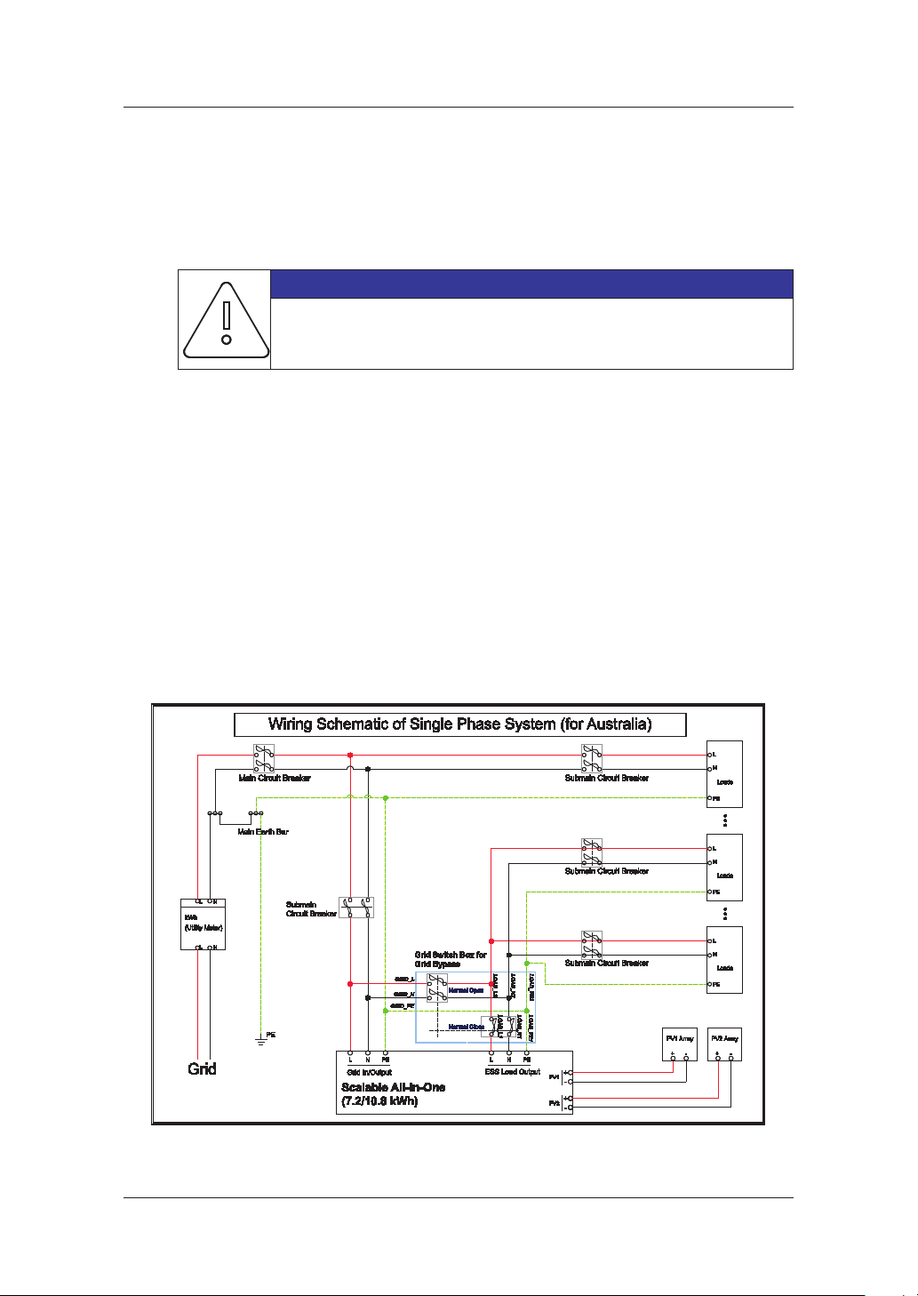
[Figure 5-17: Wiring Schematic of Single Phase System for Australia].............................................40
[Figure 5-18: Components of Grid Switch Box].........................................................................................40
[Figure 5-19: Assembling the Cable Gland]................................................................................................41
[Figure 5-20: Wiring Diagram].........................................................................................................................41
[Figure 5-21: Assembling the Wires] .............................................................................................................42
[Figure 5-22: Assembling the Sealing nuts]................................................................................................42
[Figure 5-23: Final assembly] ...........................................................................................................................43
[Figure 5-24: Assembling the Upper Part]...................................................................................................43
[Figure 5-25: Assembling the Rubber Seal] ................................................................................................44
[Figure 5-26: Assembling the Knob]..............................................................................................................44
[Figure 5-27: Final Assembly]...........................................................................................................................45
[Figure 5-28: PV connector (Female) and PV line (Male)] ......................................................................46
[Figure 5-29: Load Connector (Male) and Grid Connector (Female)]................................................46
[Figure 5-30: Connection of system for oating solar array, load and grid]...................................47
[Figure 5-31: PV connector connection (MC4 connector connection)] ...........................................47

Table of Figures
vi
[Figure 5-32: L and N AC line connection method] .................................................................................48
[Figure 5-33: Optional Actions].......................................................................................................................50
[Figure 5-34: Structure of the cable for RJ45 sleeve housing] .............................................................51
[Figure 5-35: RJ45 cable clip and the groove of RJ45 sleeve housing].............................................51
[Figure 5-36: Assembling RJ45 LAN cable] .................................................................................................52
[Figure 5-37: Fastening RJ45 LAN cable in RJ45 sleeve housing].......................................................52
[Figure 5-38: Assembling the waterproof cap set] ..................................................................................52
[Figure 5-39: Putting the sealing cap into RJ45 sleeve housing]........................................................53
[Figure 5-40: Assembling the sealing nut to RJ45 sleeve housing] ...................................................53
[Figure 5-41: Assembled RJ45 sleeve housing cable].............................................................................53
[Figure 5-42: Opening the cap of RJ45 LAN socket]................................................................................54
[Figure 5-43: Position of RJ45 LAN port]......................................................................................................54
[Figure 5-44: Inserting the assembled cable].............................................................................................54
[Figure 5-45: Upper and lower locking grooves]......................................................................................55
[Figure 6-1: Internet Connection]...................................................................................................................56
[Figure 7-1: Main page]......................................................................................................................................58
[Figure 7-2: Installer in page] ...........................................................................................................................59
[Figure 7-3: Product Information Entry Screen in Step 1] .....................................................................60
[Figure 7-4: Address Entry in Step 2].............................................................................................................61
[Figure 7-5: Product Setup Information Details Entry in Step 3].........................................................62
[Figure 7-6: Energy Rate Information Entry in Step 4]............................................................................63
[Figure 7-7: Installation Completion Screen] .............................................................................................64
[Figure 7-8: Remote Monitoring Screen].....................................................................................................65
[Figure 7-9: Selection of Product Serial No. to Test]................................................................................65
[Figure 7-10: Selection of Detailed Product Information].....................................................................66
[Figure 7-11: Operation checkup for energy meter page]....................................................................66
[Figure 7-12: ESS Operation Test Page]........................................................................................................67
[Figure 7-13: Jumper] .........................................................................................................................................69
[Figure 7-14: TCP/IP setting] ............................................................................................................................70
[Figure 7-15: Initial setup page]......................................................................................................................71
[Figure 7-16: Operating Test Screen]............................................................................................................72
[Figure 7-17: PV-Output Test Screen] ...........................................................................................................73
[Figure 7-18: Grid-Charge Test Screen]........................................................................................................74
[Figure 7-19: Battery-Discharge Test Screen].............................................................................................75
[Figure 7-20: Auto-Weak/Strong Test Screen]...........................................................................................76
[Figure 8-1: Initial indication screen on power on]..................................................................................78
[Figure 8-2: Standby state indication screen before the EMS command].......................................79
[Figure 8-3: PV generation, Battery charge, Load use, sell remaining amount]............................80
[Figure 8-4: PV generation, Battery discharge, Load use, buy shortage amount]........................80
[Figure 8-5: PV generation, Battery standby, Load use, sell remaining amount] .........................81
[Figure 8-6: PV generation, Sell remaining amount]...............................................................................81
[Figure 8-7: PV generation, Buy shortage amount] .................................................................................81
[Figure 8-8: Battery discharge, Load use]....................................................................................................82
[Figure 8-9: Battery discharge, Load use, Buy shortage amount] ......................................................82
[Figure 8-10: Indication screen on Standby Mode, Buy shortage amount]....................................82
[Figure 8-11: Indication screen on Grid charge Mode]...........................................................................83
[Figure 8-12: Indication screen on stand-alone mode]..........................................................................83
[Figure 8-13: Indication screen on Self-Reliance mode, Battery to LOAD discharge].................83
[Figure 8-14: Indication screen on Self-Reliance mode, PV to BATTERY charge (LOW SOC)]...84
[Figure 8-15: Indication screen on Application Download Mode].....................................................84
[Figure 10-1: PV MC4 connector]....................................................................................................................95
[Figure 10-2: Upper cover removal] ..............................................................................................................96
[Figure 10-3: Fan removal]................................................................................................................................96

Table of Figures
vii
[Figure 10-4: Li-Ion Battery tray (manufactured by SAMSUNG SDI)].............................................. 101
[Figure 10-5: PV Connector (MC4)] .............................................................................................................102
[Figure 11-1: Derating Curve] .......................................................................................................................106
[Figure 11-2: Power eciency curve of System]....................................................................................106
[Figure 11-3: Power eciency curve of PV Generation] .....................................................................107
1. About this Manual
1
1. About this Manual
1.1 Valid Range
This is the installation manual for the Scalable (7.2 kWh/10.8 kWh) All in One system. Please
read this installation and user manual carefully before installing and operating the scalable
all in one system.
It contains important safety instructions. The warranty will be void if you fail to follow the
instructions in this manual.
1.2 Target Group
This installation manual applies only to the Hansol Scalable All in One.
1.3 Manual Storage
The user manual and installation manual can be downloaded from the product download
section at “https://myess.hansoltechnics.com”. The specications of the product can be
changed for improvement without notice.
Also, the software can be updated automatically without notice over the Internet.
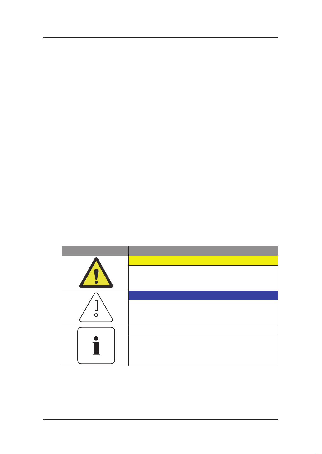
1.4 Symbols Used
Symbols Meaning
CAUTION
This symbol indicates a hazardous situation which could
result in a light injury, if not avoided.
NOTICE
This symbol indicates a hazardous situation which could
result in damage to the property, if not avoided.
Information
This symbol indicates valuable tips for optimum installation
and operation of the product.

About this Manual
2
Number Symbol Description
1 Direct current
2
Alternating current
3 Both direct and alternating current
4 Three-phase alternating current
5
Three-phase alternating current with neutral
conductor
6
Earth terminal
7
Protective conductor terminal
8
Frame or chassis terminal
9
Refer to the operating instructions
10 On (supply)
11
O (supply)
12
Equipment protected throughout by double
insulation or reinforced insulation
13
Caution: Risk of Electric Shock
14
Caution: Hot Surface

About this Manual
3
Number Symbol Description
15
Caution: Risk of Danger
16 In position of a bi-stable push control
17
Out position of a bi-stable push control
18 Input terminal or rating
19
Output terminal or rating
20
Bidirectional terminal rating
21
Caution: Risk of Electric Shock and Energy
Storage Timed Discharge
22
Caution: Risk of Hearing Damage and Wear
Hearing Protection Wear hearing protection
23
Do not dispose of the inverter with household
wastes.
For further information on disposal, refer to the
installation manual provided.
24
The CE Indication:
The relevant equipment complies with the
requirements in the EC guidelines.
25
Caution: Risk of Electric Shock and wait at least
5 min after power turn o when opening the
product.
[Table 1-1: Symbol Description]
2. Safety
4
2. Safety
2.1 Intended Use
NOTICE
The Scalable All in One system is intended for residential use only.
The Scalable All in One system should not be used for commercial or
building.
The Scalable All in One system is designed for residential use. It is a single-phase, grid-
connected system of solar energy sources and Li-Ion Battery energy storage.
The Scalable All in One system uses solar energy power connected to the input/output
terminal installed on the side of the device in order to:
1) charge the Li-Ion battery energy storage,
2) provide a supply to the household load, and
3) convert direct current (DC) electricity of the battery to alternating current (AC) to
discharge as household single-phase load or electric system.
This device should not be used for any purpose other than the purpose described in this
installation manual. Any substitute use of this device, random change in any of its parts, and
use of components other than sold or recommended by Hansol Technics will nullify the
product’s guarantee. For example, Hansol Li-Ion battery energy storage should not be
replaced by other manufacturer’s battery storages. For further information on proper use of
this device, contact the Hansol Technics Service line or visit at“www.hansoltechnics.com”
[Figure 2-1: Connection Diagram]
2. Safety
5
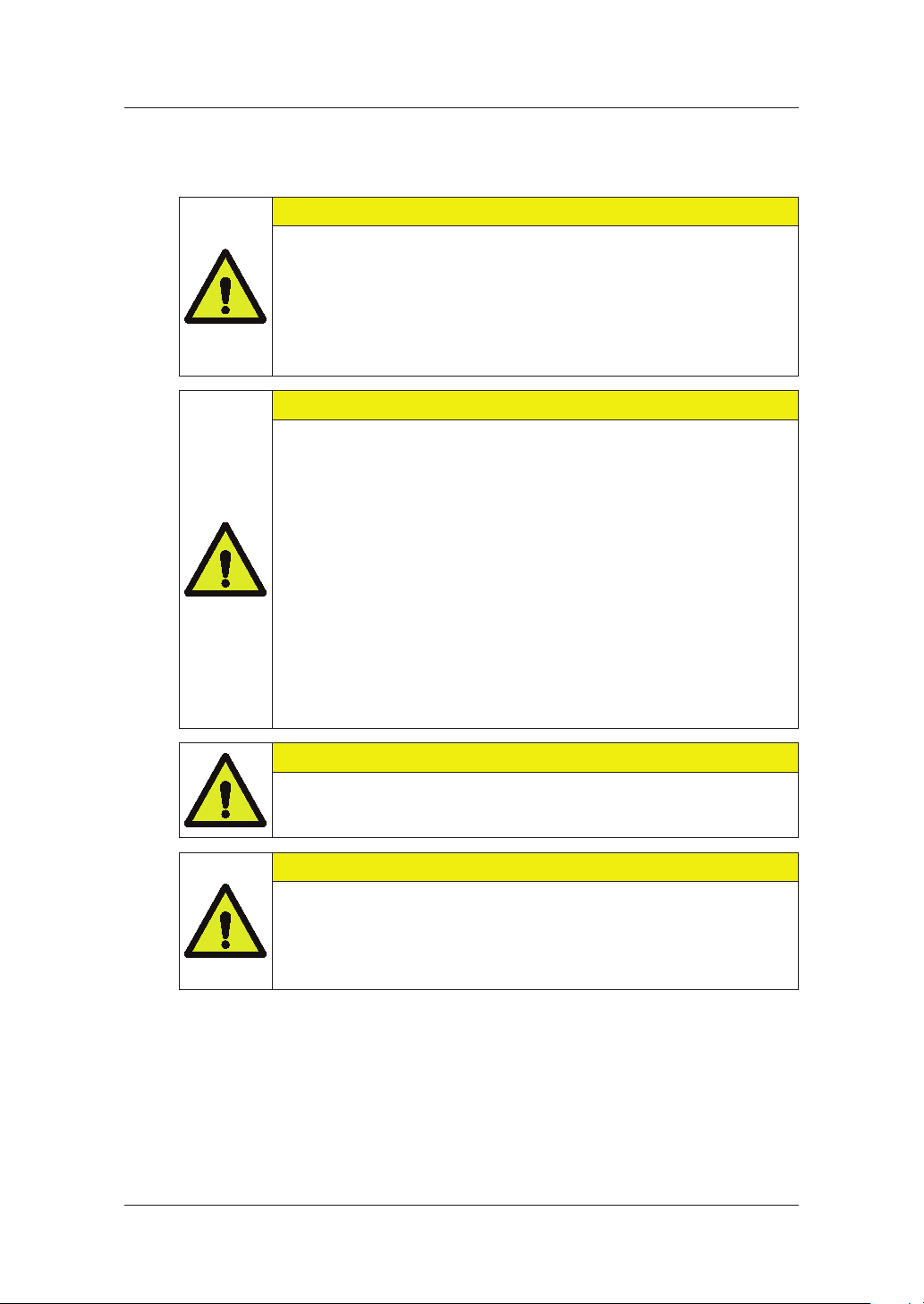
2.2 Safety Precautions
CAUTION
High voltages in power conditioning circuits. Lethal hazard of electric shock
or serious burns.
All work on the PV modules, inverters, converters, and battery systems must
be carried out by qualied personnel only.
Wear rubber gloves and protective clothing (protective glasses and boots)
when working on high voltage/high current systems such as INVERTER and
battery systems.
CAUTION
Li-Ion battery energy storage system (ESS) inside. When assembling the
system, do not intentionally short the positive (+) and negative (-) terminals
with metallic object.
All work on the ESS and electrical connections must be carried out by
qualied personnel only. The ESS within Scalable All in One provides a safe
source of electrical energy when operated as intended and as designed.
A potentially hazardous circumstance such as excessive heat or electrolyte
mist may occur due to improper operating conditions, damage, misuse
and/or abuse. The following safety precautions and the warning messages
described in this section must be observed. If any of the following
precautions are not fully understood, or if you have any questions, contact
Customer Support for guidance (see chapter 13).
The safety section may not include all regulations for your locale; personnel
working with Scalable All in One must review applicable federal, state and
local regulations as well as the industry standards regarding this product.
CAUTION
This product is intended to be used for PV source inputs and residential
home grids (AC 230V). If not used as intended, the protection provided by
the equipment may be impaired.
CAUTION
This device is designed appropriate for two-PV string structure. Therefore, the
PV string 1 and PV string 2 must be connected to PV input 1 and PV input 2,
respectively.
Do not split one PV string output for connecting it into the PV input terminal
1 and input terminal 2.
2. Safety
6
2.3 Product Overview
The All in One system includes the PV inverter, battery charger/discharger, Li-Ion battery, and
EMS.
The basic operating modes consist of PV generation mode, PV generation +
charge/discharge mode. The operation mode of this product is automatically determined by
the EMS algorithm.
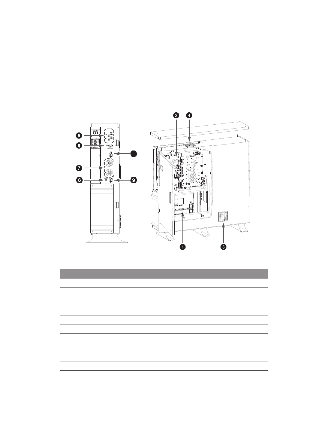
[Figure 2-2: Part View of Hansol All in One]
No. Description
1 Lithium Ion battery
2 INVERTER & Converter (PV inverter and battery charger / discharger)
3 Air Filter1 (Bottom)
4 Air Filter2 and FAN (Top)
5 Input terminal (MC4-2set)
6 DC isolator
7 Grid and Load connector (RST50i5S connector)
8 Service Connecter for Installation
9 Communication (LAN)
10 DRM Connection (LAN)
[Table 2-1: Part Description]
10
2. Safety
7
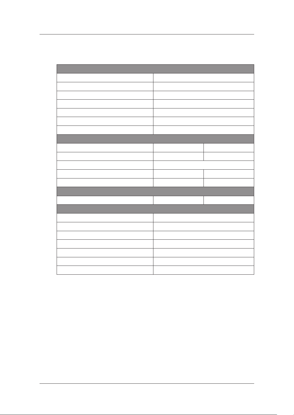
2.3.1 Basic Specications
PV Generator Data (DC)
Max. input total power 6.6 kWp
Max. input power per string 3.3 kWp
Max. input voltage 550 V
Min. input voltage/Initial input voltage 125 V/150 V
MPPT voltage range 125 V~500 V
Max. input current per string 15 A
Number of independent MPP trackers 2
Battery Data (DC)
System model No. ELSR722-00004 ELSR103-00001 (*)
Battery rated capacity 7.2 kWh 10.8 kWh
DOD (Depth of Discharge) 90 % (6000cycles, 5 ~ 95 %),
Battery voltage range/nominal voltage 96 ~ 132 V / 120 V 145 ~ 198 V / 180 V
Battery Max. current 46 A 38 A
Battery DC/DC Converter Data
Rated power 4.0 kW 4.98 kW
Grid Connection Data (AC)
Rated power 4.98 kW
Max. apparent AC power 4.98 kVA
Max. output current 22 A
Max. input AC power 8 kW
Max. allowed current for fuse protection 43 A
Nominal AC voltage/range 230 V/200 V~270 V
Rated power frequency 50 Hz
(*):2 battery trays for 7.2 kWh; 3 battery trays for 10.8 kWh
[Table 2-2: Basic Specications]
2.3.2 Grounding the PV Inverter
The PV inverter complies with the local requirements for grounding the PV inverter.
Hansol Technics recommends connecting and grounding the PV inverter’s frame and other
electricity conducting surfaces in such a way that there is continuous conduction in order to
achieve maximum protection for systems and persons. And the PV inverter’s DC (+) pole
and DC (-) pole are not permitted to be grounded.
2. Safety
8
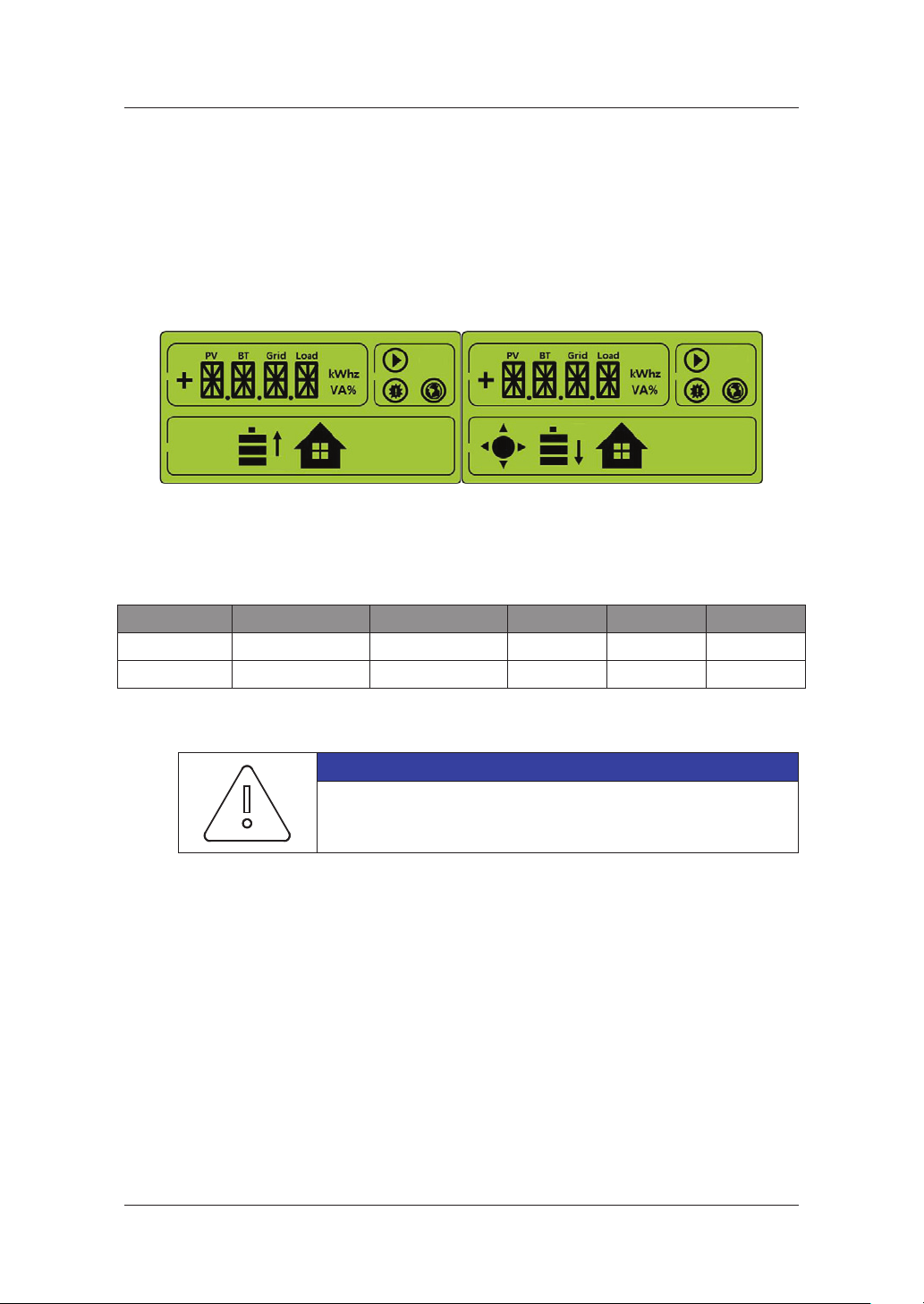
2.3.3 Fail-safe actions upon power failure
When a system outage occurs, the utility pole in the following gure disappears and it
switches to the backup mode after 20 seconds to supply power. With 7.2 kWh, the supplied
power is a maximum of 4 kW and with 10.8 kWh, a maximum of 4.98 kW.
The back mode is canceled in 5 minutes after return to normal operation.
The utility pole appears when power is supplied to the system. Upon system outage, it
disappears. Upon PV generation, the sun mark appears.
[Figure 2-3: Back up mode (LCD)]
Under DOD 90% and 95% of battery to loads, the 7.2 kWh system can operate for approx. 92
minutes and the 10.8 kWh system for approx. 110 minutes.
System Battery capacity Battery energy Load Hour Min
7.2 kWh 7.2 kWh 6.48 kWh 4 kW 1.5 92.3
10.8 kWh 10.8 kWh 9.72 kWh 4.98 kW 1.8 110.8
[Table 2-3: Maximum Outage Response Times for each System with Battery Full]
NOTICE
The outage response time may vary depending on the battery
capacity and loads.

3. Package Removal and Inspection
9
3. Package Removal and Inspection
CAUTION
Included in this box are a battery and printed circuit board, and the entire
weight amounts to 105 kg. Therefore, special care must be taken in handling.
Make sure to have at least two persons deliver with something like trolleys
and remove the package.
3.1 Package Removal and Tray Assembly
3.1.1 Removing the Enclosure Package
As shown in the gure in this section, remove the package components from the enclosure
in the following order.
1. Place the system on the installation location.
2. Open the upper part of the system case.
3. Remove top side of the cover in the front of the product.
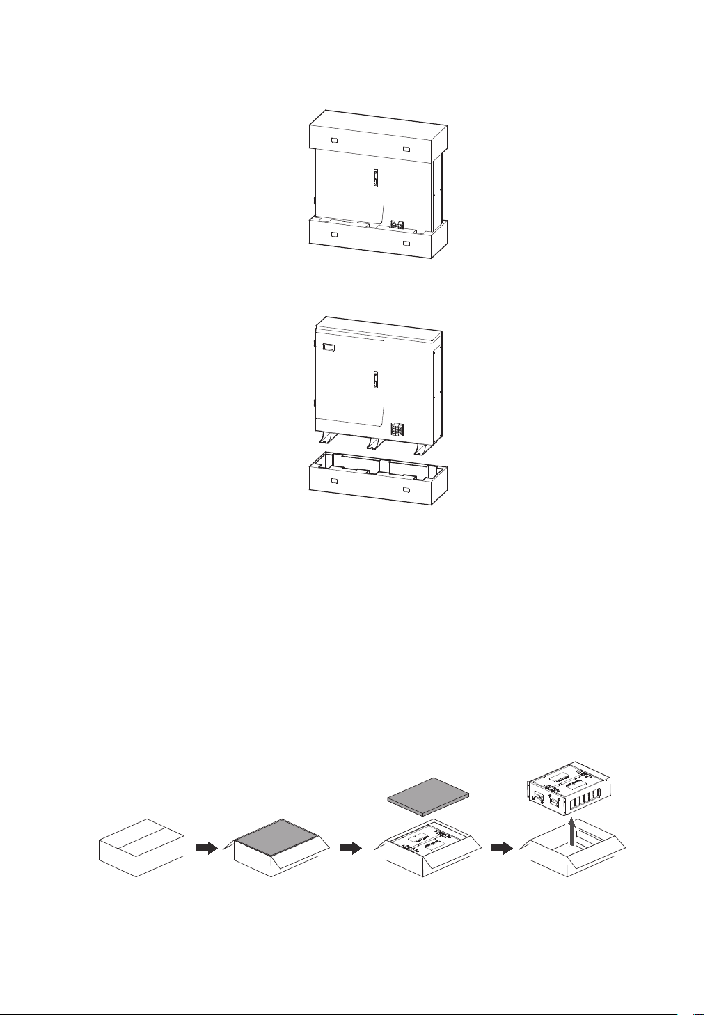
3. Package Removal and Inspection
10
4. Open the side support on the bottom.
[Figure 3-1: Process for the enclosure package removal]
3.1.2 Removing the Battery Tray Package
As shown in the [Figure 3-2], remove the package for the battery tray.
1. Open the box cover of the product.
2. Remove the buers with a straight pull.
3. Take out the battery tray by grabbing the handle and pulling it up.
Note: The tray weighs approximately 45 kg, so make sure to have at least two persons
lift it.
[Figure 3-2: Process for the battery package removal]

3. Package Removal and Inspection
11
3.1.3 Checking Components on the Packing List
Once the product has been delivered, refer to the gure [Figure 3-3] and [Table 3-1], identify
the entire components included in the package and the correct number of the quantity
listed in the table.
Packing List
[Figure 3-3: Packing List]
Object Part Name Code No. Quantity
A INVERTER ASSY SJ94-00146A or SJ94-00147A 1
B TRAY ASSY ELPT362-00004 2 or 3(*)
C 1. SCREW(M4xL8)
2. LAN Connector
3. GRID Connector
4. LOAD Connector
5. Service Connector
6. DOOR KEY
7. Grid Switch Box
6001-002698
VS-08-T-H-RJ45/IP67
97.051.4253.1
97.052.4253.1
A366-CP-T0651
3406-001136
12
2
1
1
1
2
1
D Installation Quick Guide
Manual
SJ68-02142A 1
(*):2 battery trays for 7.2 kWh system; 3 battery trays for 10.8 kWh system
[Table 3-1: Component Description]

3. Package Removal and Inspection
12
3.1.4 Assembling the Battery Tray
The [Figure 3-4] shows the assembly process for the battery tray. Refer to Clause 5.4 and
assemble the battery tray as described in it.
[Figure 3-4: Process for the battery assembly (For 10.8 kWh System)]
3.2 Checking for damage in Delivery
When opening the box that contains Hansol Scalable All in One system in it, check for any
possible damage caused in transit and ensure the correct number of the components
therein. If there is a scratch on the enclosure, contact your local dealer for inspection and
service.
This manual suits for next models
2
Table of contents
Other Hansol Camera Accessories manuals

Popular Camera Accessories manuals by other brands

FeiYu Tech
FeiYu Tech G3 Steadycam installation instructions

RecorderGear
RecorderGear CG300 instruction manual

Redrock Micro
Redrock Micro Scout HS quick start guide

Sea & Sea
Sea & Sea YS-250PRO instruction manual

Alto-Shaam
Alto-Shaam FryTech Series Installation operation & maintenance

Cambo
Cambo RPS-SYSTEM instruction manual


