Deka unigy I User manual
STATIONARY BATTERY INSTALLATION
AND OPERATING INSTRUCTIONS
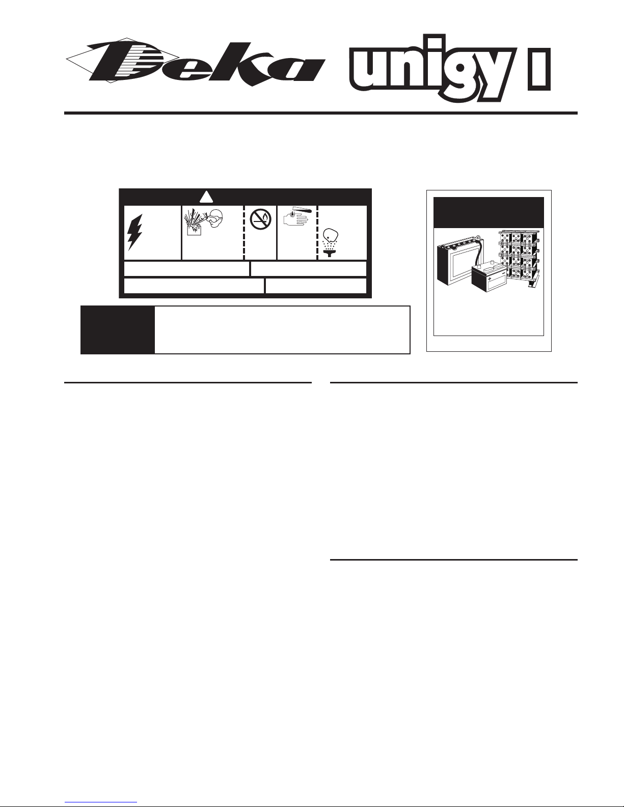
DANGER
!
SHIELD EYES
EXPLOSIVE GASES
CAN CAUSE BLINDNESS
ORINJURY.
NO.
•
SPARKS
•
FLAMES
•
SMOKING
SULFURIC
ACID
CAN CAUSE
BLINDNESS OR
SEVERE BURNS.
FLUSH EYES
IMMEDIATELY
WITH WATER.
GET
MEDICAL
HELP
FAST.
HIGH
VOLTAGE...
RISK OF SHOCK.
DO NOT TOUCH
UNINSULATED
TERMINALS OR
CONNECTORS.
DO NOT REMOVE VENT VALVE.
WARRANTY VOID IF VENT VALVE IS REMOVED.
VENTILATE WELL WHEN IN AN ENCLOSED
SPACE AND WHEN CHARGING.
REPAIR SHOULD BE PERFORMED ONLY
.BY A QUALIFIED SERVICE TECHNICIAN.
SEE INSTALLATION, MAINTENANCE AND OPERATION
INSTRUCTIONS FOR IMPORTANT SAFETY PRECAUTIONS.
SAFETY PRECAUTIONS
Although all valve-regulated batteries have the elec-
trolyte immobilized within the cell, the electrical hazard
associated with batteries still exists. Work performed on
these batteries should be done with the tools and the
protective equipment listed below. Valve-regulated
battery installations should be supervised by personnel
familiar with batteries and battery safety precautions.
Protective Equipment
To assure safe battery handling, installation and
maintenance, the following protection equipment
should be used:
1. Safety glasses or face shield
2. Acid-resistant gloves
3. Protective aprons and safety shoes
4. Proper lifting devices
5. Properly insulated tools
Procedures
The following safety procedures should be followed
during installation: (Always wear safety glasses or
face shield.)
1. These batteries are sealed and contain no free elec-
trolyte. Under normal operating conditions, they do not
present any acid danger. However, if the battery jar or
cover is damaged, acid could be present. Sulfuric acid
is harmful to the skin and eyes. Flush affected area
with water immediately and consult a physician if
splashed in the eyes.
2. Prohibit smoking and open flames, and avoid arcing in
the immediate vicinity of the battery.
3. Do not wear metallic objects, such as jewelry, while
working on batteries.
4. Keep the top of the battery dry and clear of all tools and
other foreign objects.
5.
Provide adequate ventilation (per IEEE standard 1187 and
/or local codes) and follow recommended charging voltages
.
SAFETY PRECAUTIONS (con’t)
Procedures (con’t)
6. Extinguishing media: Class ABC extinguisher. Note:
CO2may be used but not directly on the cells due
to thermal shock and potential cracking of cases.
7. Never remove or tamper with pressure relief valves.
Warranty void if vent valve is removed.
8. Inspect all flooring and lifting equipment for functional
adequacy.
9. Adequately secure battery modules, racks, or cabinets
to the floor.
10. Connect support structure to ground system in accor-
dance with applicable codes.
RECEIVING AND STORAGE
Receiving Inspection
Upon receipt, and at the time of actual unloading, each
package should be visually inspected for any possible
damage or electrolyte leakage. If either is evident, a
more detailed inspection of the entire shipment should
be conducted and noted on the bill of lading. Record
receipt date, inspection data and notify carrier of any
damage.
Unpacking
1. Always wear eye protection.
2. Check all batteries for visible defects such as cracked
containers, loose terminal posts, or other unrepairable
problems. Batteries with these defects must be replaced.
3. Check the contents of the package against the packag-
ing list. Report any missing parts or shipping damage
to your East Penn agent or East Penn fg. Co.
immediately.
4. Never lift batteries by the terminal posts.
5.
Always lift batteries by the bottom or use the lifting handles.
®
®
BATTERIES
AND OTHER RELATED PARTS
CONTAIN LEAD
Form No: 1314 Rev. 8/08 Must be posted in workplace near batteries.
WARNING:
Battery posts, terminals and related accessories
contain lead and lead compounds, chemicals
known to the State of California to cause
cancer and reproductive harm.
Batteries also contain other chemicals known
to the State of California to cause cancer.
WASH HANDS AFTER HANDLING!
Batteries, attery posts, terminals and related accessories
contain lead and lead compounds, and other chemicals known
to the state of California to cause cancer and irth defects or
other reproductive harm. Wash hands after handling.
Cali ornia
Proposition 65
Warning

Battery Type Torque/Retorque inch lbs (newton meters)
12AVR30/40 45 ± 5 (5.1 ± .5)
All types except
12AVR30/40 60 ± 5 (6.8 ± .5)
RECEIVING AND STORAGE (con’t)
Storage
1. Cells should be stored indoors in a clean, level, dry and
cool location. Recommended storage temperature is 0°F
to 90°F (–18°C to 32°C).
2. Stored lead-acid batteries self discharge and must be
given a charge six months from date of manufacture
to prevent permanent performance degradation.
Record dates and conditions for all charges during
storage.
3. Recommended charge during storage is at a constant
voltage of .30 volts per battery greater than recom-
mended float voltage for 24 hours. (Reference the float
voltage chart on next page.)
4. Do not store beyond 12 months.
INSTALLATIONS
General
Caution should be taken when installing batteries to
insure no damage occurs. The battery cabinet, tray,
rack, etc. shall be inspected for sharp edges that could
cause damage to the battery casing. Batteries shall not
be dropped, slid, placed on rough or uneven surfaces
such as tray lips or grated flooring. ishandling of
batteries could result in equipment damage or human
injury. East Penn will not be liable for damage or injury
as a result of mishandling or misuse of the product.
Grounding
When grounding the battery system, proper techniques
should be applied per electrical standards, such as NEC
and/or local codes.
Cabinets
Cabinet systems come factory assembled and prewired.
Do not tip or turn cabinets on their sides when position-
ing them in their intended installation area. Cabinets
must be used in an upright position. These systems
are preconnected. Only inter-shelf, inter-cabinet and
connections to the load are required. See the connection
diagram inside the cabinet. Inter-cabinet and load
connection cables are not included.
Racks
Assemble racks in accordance with the intended
arrangement, align with a level and bolt to the floor.
See rack assembly instructions.
BATTERY ASSEMBLY
(Always wear eye protection.)
1. Set up the batteries so that the positive post (+) of one
battery is connected to the negative post (–) of the next
battery for all series connections.
2. The intercell connector contact surfaces shall be cleaned
by rubbing gently with a non-metallic brush or pad before
installing connectors. No-ox-ID grease can be used but
is not required.
3. Install all intercell connectors loosely to allow for final
alignment of batteries, then torque. (See Table 1 for
correct torque/retorque values.)
BATTERY ASSEMBLY (con’t)
General
1. Install the lockwasher and torque the terminal bolts or
nuts. (See Table 1 for correct torque values.)
DO NOT OVERTOR UE. Some batteries have cable
harnesses (torque value is 45 ± 5).
2. After torquing the connections on racked batteries, read
the voltage of the battery string to assure that individual
batteries are connected correctly. The total voltage should
be approximately equal to the number of batteries times
the measured voltage of one battery (when connected in
series). If the measurement is less, recheck the connections
for proper voltage and polarity.
3. Read and record intercell connection resistance and
note the method of measurement. This helps determine
a satisfactory initial installation and can be used as a
reference for future maintenance requirements. See
Appendix A, recording forms, in the back of the manual.
Clean, remake and remeasure any connection having
a resistance measurement greater than 10% of the
average of all the same type of connections (inter-
cell, inter-tier or shelf, inter-rack or inter-cabinet).
4. Battery performance is based on the output at the battery
terminals. Therefore, the shortest electrical connections
between the battery system and the operating equipment
results in maximum total system performance.
Do not select cable size on current carrying
capability only. Cable size should not provide a greater
voltage drop between the battery system and operating
equipment than specified. Excess voltage drop will
reduce the desired support time of the battery system.
®
®
Table 1 — Torque/Retorque Values

SYSTEM OPERATION
Charger Voltage
These batteries are designed for continuous float
applications. When setting the float voltage on the
charger, the system should be set to float at the nominal
battery float voltage times the number of batteries.
The charger must be able to maintain the system
voltage within ±0.5% of the desired level at all times.
The desired float voltage varies with temperature
according to the table below.
The average battery operating temperature should not
exceed 95°F (35°C) and should never exceed 105°F
(40.5°C) for more than an eight-hour period.
Operating at temperatures greater than 77°F (25°C)
will reduce the operating life of the battery. If operating
temperatures are expected to be in excess of 95°F
(35°C), contact East Penn for recommendations.
Battery Voltage
Although the charger must maintain the system voltage
within ±0.5%, individual battery voltages may vary by
±0.30 volts of the average battery float voltage.
RECORD KEEPING
Voltages, Temperatures & Ohmic Readings
Record keeping is an important part of stationary battery
maintenance and warranty coverage. This information
will help in establishing a life history of the battery and
inform the user if and when corrective action needs to
be taken. (Refer to Appendix A, Battery aintenance
Report)
While it is acceptable to operate at temperatures less
than 77°F (25°C), it will require longer charging time to
become fully recharged. Also, the capacity will be less
at operating temperatures below 77°F (25°C).
After installation and when the batteries have been on
float charge for one week, the following data should be
recorded:
1. Battery string terminal voltage
2. Charger voltage
3. Individual battery float voltages
4. Individual battery ohmic readings
5. Ambient temperatures
RECORD KEEPING (con’t)
Voltages, Temp. & Ohmic Readings (con’t)
6. Terminal connections should be checked to verify that
the installer did torque all connections properly. icro-
ohm readings should be taken across every connection.
Refer to meter manufacturer’s instructions for proper
placement of probes. If any reading differs by more than
20% from its initial installation value, re-torque the con-
nections. If the reading still remains high, clean contact
surfaces according to Step 2 under Battery Assembly.
MAINTENANCE
Always wear eye protection when working on or near
batteries. Keep sparks and open flames away from
batteries at all times.
Annual Inspection(1)
1. Conduct a visual inspection of the battery(ies).
2. Record the battery string voltage.
3. Record the charger voltage.
4. Record the individual battery voltages. The accuracy of
the D (Digital ultimeter) must be .05% (on dc scale)
or better. The D must be calibrated to NIST traceable
standards. Because float readings are affected by
discharge and recharges, these readings must be taken
when batteries have been on continuous, uninterrupted
float for at least one month. Batteries should be within
± 0.30 volts of the average battery float voltage.
5. Record the ambient temperatures.
6. Record individual battery ohmic readings.
7. Record all interunit and terminal connection resistances.
icro-ohm readings should be taken during this
inspection. If any reading differs by more than 20%
from inital readings taken, retorque the connection.
Recheck the micro-ohm reading. If the reading remains
high, clean the contact surface according to installation
portion of this manual.
(1)
Other Maintenance Inspection intervals follow IEEE 1188.
Rectifier Ripple Voltage
Acceptable charging ripple (peak to peak) shall be less
than 0.5% of the manufacturer’s recommended string
float voltage or have a duration shorter than 8 millisec-
onds.
Battery Cleaning
Batteries, cabinets, racks, and modules should be
cleaned with clear water. If neutralizing is required,
use a mixture of baking soda and water. Use clear
water. Never use solvents to clean the battery.
Capacity Testing
Do not discharge the batteries beyond the specified final
voltage. When discharging at higher rates, extra connec-
tors may need to be added to prevent excessive voltage
drop. When performing capacity testing and recording
data use IEEE 1188 instructions. Should it be deter-
mined that any individual battery(ies) or cell(s) need
to be replaced, contact your nearest East Penn agent
or East Penn Service Center.
Per Battery Float Voltage ± .06 volts
Battery
Temperature AAllll UUnniiggyy ttyyppeess
eexxcceepptt
° F ° C 1122AAVVRR110000EETT
1122AAVVRR110000EETT
50° 10°
59° 15°
68° 20° 13.50 13.62
77° 25°
86° 30°
95° 35° 13.38 13.50
®
®

APPENDIX A
Charger Output ____________________Amp Air Temperature ____________________°F
Total Battery String Voltage _______________ Panel eter Volts ____________________
Year _______________________ Year _______________________ Year _______________________ Year _______________________
Unit Ohms or Unit Ohms or Unit Ohms or Unit Ohms or
Number Volts Mhos Number Volts Mhos Number Volts Mhos Number Volts Mhos
BATTERY MAINTENANCE REPORT
Inspection Date_______________________________________________________________ No. of Units/String _________________
Company ___________________________________________________________________ Type ____________________________
Address ____________________________________________________________________ Date New ________________________
Battery location and/or number __________________________________________________ Date Installed _____________________
Readings Taken By ____________________________ Remarks/Recommendations __________________________________________________________
Readings should be taken at installation and annually thereafter. _________________________________________________________________________________
1111
2222
3333
4444
5555
6666
7777
8888
9999
10 10 10 10
11 11 11 11
12 12 12 12
13 13 13 13
14 14 14 14
15 15 15 15
16 16 16 16
17 17 17 17
18 18 18 18
19 19 19 19
20 20 20 20
21 21 21 21
22 22 22 22
23 23 23 23
24 24 24 24
25 25 25 25
26 26 26 26
27 27 27 27
28 28 28 28
29 29 29 29
30 30 30 30
31 31 31 31
32 32 32 32
33 33 33 33
34 34 34 34
35 35 35 35
36 36 36 36
37 37 37 37
38 38 38 38
39 39 39 39
40 40 40 40
Avg. Voltage Avg. Voltage Avg. Voltage Avg. Voltage
Individual
Battery Readings
®
®
Lyon Station, PA 19536-0147 • Phone: 610-682-6361 • Fax: 610-682-4781
Order Department Hotline: 610-682-4231
www.eastpennunigy.com • E-mail: [email protected]
E.P.M. Form No. 0902 Rev. 12/09 © 2009 y EPM Printed in U.S.A.
All data su ject to change without notice.
No part of this document may e copied or reproduced, electronically
or mechanically, without written permission from the company.
DISTRIBUTED BY:
“P O W E R E D F O R P E R F O R M A N C E ”®
Table of contents
Other Deka Camera Accessories manuals

Deka
Deka Unigy I User manual

Deka
Deka Unigy II User manual

Deka
Deka Unigy II User manual

Deka
Deka unigy II SPACESAVER Non-Interlock AVR 45 AH User manual

Deka
Deka unigy User manual

Deka
Deka 8A User manual

Deka
Deka Unigy II AVR45 Series User manual

Deka
Deka Dominator Gel-Mate SVRLA G105 User manual

Deka
Deka Dominator Gel-Mate SVRLA G45 User manual

Deka
Deka EZ LINK D35 User manual


Popular Camera Accessories manuals by other brands


Trojan
Trojan GC2 48V quick start guide

Calumet
Calumet 7100 Series CK7114 operating instructions

Ropox
Ropox 4Single Series User manual and installation instructions

Cambo
Cambo Wide DS Digital Series Main operating instructions

Samsung
Samsung SHG-120 Specification sheet

Ryobi
Ryobi BPL-1820 Owner's operating manual