HB-THERM T24693 User manual

Temperatur Control Technology
www.hb-therm.ch
M8100-EN 2018-03 1/8
2018-03
Page
Assembly Instructions
M8100-EN
Spare part flow rate measuring board DFM-51 (O/ID T25605)
Purpose
Replacement of flow rate measuring board DFM-51 (A 9)
Precondition
WARNING!
Danger for unauthorized persons!
Conversion work may only be carried out by
specialist staff who have been trained accordingly.
Therefore:
–Keep unauthorized persons away from the work
area.
NOTE!
Knowledge of the Instruction Manual is a
precondition for carrying outconversion work on the
unit.
Procedure
DANGER!
Danger to life caused by electric current!
Touching conductive parts causes a direct danger
to life.
Therefore:
–For all work on the electrical system, for
maintenance, cleaning or repair work,
disconnect from the mains or disconnect all
phases of the external power supply and secure
them against being switched on again. Check
unit is isolated from power supply.
WARNING!
Danger of crushing due to rolling away or
tipping
With an uneven floor or when the castors are not
locked, there is a danger that the unit tips over or
rolls away causing crushing.
Therefore:
–Only install the unit on an even floor.
–Ensure that the castors are locked.

Assembly Instructions M8100-EN
M8100-EN 2018-03 2/8
1. Proceed as follows in order to cool down the unit and empty
the mould (mould evacuation)
Display menu page Functions.
Select the function Cooling and activate with the key.
Select the function Mould evacuation and activate with the
key.
The activated function is indicated with the symbol.
2. Main switch off, remove the plug from the mains and empty
the unit.
3. Remove control cable to ext. flow rate meter Flow-5.
Fig. 1: Front side of the evaluation unit
Fig. 2: Rear side of the evaluation unit
4. Proceed as follows in order to remove the cover of the
evaluation unit:
Remove screws (Label 1 Fig. 1).
Detach screws (Label 2 Fig. 2).
Lift the cover with the keyboard and pull out the ribbon cable.
Remove the cover with the keyboard.
Fig. 3: DFM-51 evaluation unit
5. Proceed as follows in order to replace the printed circuit board
DFM-51 (A 9):
Pull out plug connections of printed circuit board DFM-51.
Remove screws (Label 3 Fig. 3).
Remove printed circuit board DFM-51 and insert new one in the
evaluation unit.
Attach screws (Label 3 Fig. 3).
Connect plug connections to the printed circuit board.
1
2
3

Assembly Instructions M8100-EN
M8100-EN 2018-03 3/8
Fig. 4: Front side of the evaluation unit
Fig. 5: Rear side of the evaluation unit
6. Proceed as follows in order to attach the cover of the
evaluation unit:
Connect the ribbon cable to the keyboard and attach the cover.
Attach screws (Label 1 Fig. 4).
Tighten screws (Label 2 Fig. 5).
7. Connect control cable to ext. flow rate meter Flow-5.
8. Reconnect mains plug and switch on main switch.
9. Switch the unit on with the key.
NOTICE!
Software version SW51-1_1335 or higher is
required for the printed circuit board DFM-51
(acceptance date 1253 and later). If necessary
perform a software-update (
Thermo-5 operating
instructions)
1
2

Assembly Instructions M8100-EN
M8100-EN 2018-03 4/8
NOTICE!
If a new printed circuit board DFM-51 (A 9) is
recognised, the configuration is requested
automatically via the input window.
Fig. 6: Warning configuration notice
Fig. 7: Entry of configuration
10. Proceed as follows to assemble the new printed circuit board
DFM-51 (A 9):
Change to the next screen page with the key.
Configure ext. flow rate meter (information on the rating
plate)
Select the Apply configuration function and activate with the
key.
The activated function is indicated with the symbol.
11.Assigning the ext. flow rate meter address (Operating
instructions Flow-5, registering of new external Flow rate
meter)

Assembly Instructions M8100-EN
M8100-EN 2018-03 5/8
12.Proceed as follows to calibrate the flow rate metre:
When setting parameters set DFM recognition to the
"integrated" value (in Settings / Miscellaneous), continue with
Step 13.
When setting parameters set DFM recognition to the "modular"
value (in Settings / Miscellaneous), continue with Step 14.
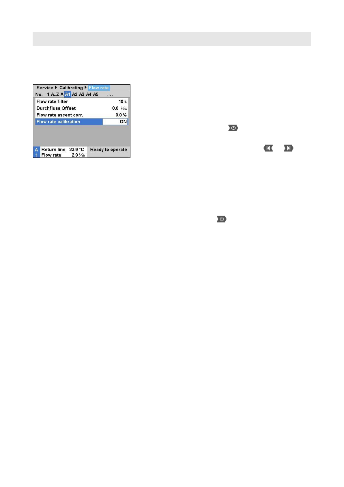
Fig. 8: Calibrate flow rate during integrated
operation
Integrated operation
13. Proceed as follows to calibrate the corresponding flow rate
metre:
(from software version SW51-1 0849B)
In normal operation operate the device at 40 °C for at least 10
minutes.
Only in the case of water units:
If present set the parameter Pressure relief with unit OFF at
Setting / Miscellaneous to "OFF".
Switch the unit off using button and wait at least 10
seconds.
Set corresponding parameter Flow rate ext. 1..8 Calibration at
Service / Calibration / Flow rate external 1 to 4 or Service /
Calibration / Flow rate external 5 to 8 to "ON".
The flow rate is calibrated automatically.
Only in the case of water devices:
If present set the parameter Pressure relief with unit OFF at
Setting / Miscellaneous to "ON".
Switch the unit on with the key.
Fig. 9: Calibrate flow rate during integrated
operation (<SW51-1 0849B)
(up to software version SW51-1 0849B)
In normal operation operate the device at 40 °C for at least 10
minutes.
Set corresponding parameter Flow rate ext. … offset at Service
/ Calibration / Flow rate external 1 to 4 or Service / Calibration /
Flow rate external 1 to 4 to "5 L/min".
Close the corresponding shut-off valve between the feed and
return line and wait for 1 minute.
Read current Flow rate.
Set the parameter Flow rate ext. … offset according to the
following calculation:
Flow rate ext. … offset new = 5 –flow rate as it currently stands
Opening the shut-off valve

Assembly Instructions M8100-EN
M8100-EN 2018-03 6/8
Fig. 10: Calibrate flow rate during modular
operation
Operation Modular
14.Proceed as follows to calibrate the corresponding flow rate
metre:
In normal operation operate the device at 40 °C for at least 10
minutes.
Only in the case of water devices:
If present set the parameter Pressure relief with unit OFF at
Setting / Miscellaneous to "OFF".
Switch the unit off using button and wait at least 10
seconds.
Select the module affected e.g. "A1" with the or
buttons.
Set parameter Flow rate calibration at Service / Calibration /
Flow rate to "ON".
The flow rate is calibrated automatically.
Only in the case of water devices:
If present set the parameter Pressure relief at unit OFF at
Setting / Miscellaneous to "ON".
Switch the unit on with the key.
15.Inspection of calibration of Flow rate meter
In normal operation operate the unit at 40 °C for at least 5
minutes following calibration.
Close the corresponding shut-off valve between main and
return lines.
Flow rate returns to 0 L/min.
If this is not the case repeat the Flow rate meter point.
Repeat the Flow rate meter calibration item for each measuring
circuit.

Assembly Instructions M8100-EN
M8100-EN 2018-03 7/8
16.Proceed as follows in order to calibrate the temperature
sensor:
When setting partameters set DFM recognition to the
"integrated“ value (in Settings / Various), continue with Step 17.
When setting parameters set DFM recognition to the "modular“
value (in Settings / Various), continue with Step 18.
Fig. 11: Sensor calibration during
integrated operation
Integrated operation
17. Temperature sensor main line ext 1..8 and temperature
sensor return line ext. Proceed as follows in order to calibrate
1..8 , if necessary, the temperature sensor:
With a constant deviation set parameter Sensor… offset under
Service / Calibration / Temperature.
With a linear deviation, set parameter Sensor… asc.cor. under
Service / Calibration / Temperature.
Fig. 12: Sensor calibration during modular
operation
Operation Modular
18. Proceed as follows, if necessary calibrate the temperature
sensor for the main line and temperature sensor of the return
line:
Select the module affected e.g. "A1“ with the or
buttons.
With a constant deviation set parameter Sensor… offset under
Service / Calibration / Temperature.
With a linear deviation, set parameter Sensor… asc.cor. under
Service / Calibration / Temperature.
19.Check unit functions.
20.Switch the unit off by press the key.
21.Main switch off.

Assembly Instructions M8100-EN
M8100-EN 2018-03 8/8
Parts list
Pos
Description
O/ID
Pcs
01
Flow rate measuring board DFM-51
T24693
1
02
Assembly instructions German
M8100-DE
1
03
Assembly instructions English
M8100-EN
1
04
Assembly instructions French
M8100-FR
1
Table of contents
Other HB-THERM Power Supply manuals